外文翻译格式示范
外文翻译格式

本科毕业设计(论文)外文翻译译文
学生姓名:
院(系):
专业班级:
指导教师:
完成日期:20 年月日
要求
1、外文翻译是毕业设计(论文)的主要内容之一,必须学生独立完成。
2、外文翻译译文内容应与学生的专业或毕业设计(论文)内容相关,不得少于15000印刷符号。
3.外文翻译译文用A4纸打印。
文章标题用3号宋体,章节标题用4号宋体,正文用小4号宋体,20磅行距;页边距上、下、左、右均为2.5cm,左侧装订,装订线0.5cm。
按中文翻译在上,外文原文在下的顺序装订。
4、年月日等的填写,用阿拉伯数字书写,要符合《关于出版物上数字用法的试行规定》,如“2005年2月26日”。
5、所有签名必须手写,不得打印。
文献名称(中文)
文献名称(外文)
作者: ***
起止页码:
出版日期(期刊号):
出版单位:(以上文字用小4号宋体,数字、字母用Times New Roman体)外文翻译译文:(小4号宋体)。
毕业论文外文翻译格式【范本模板】

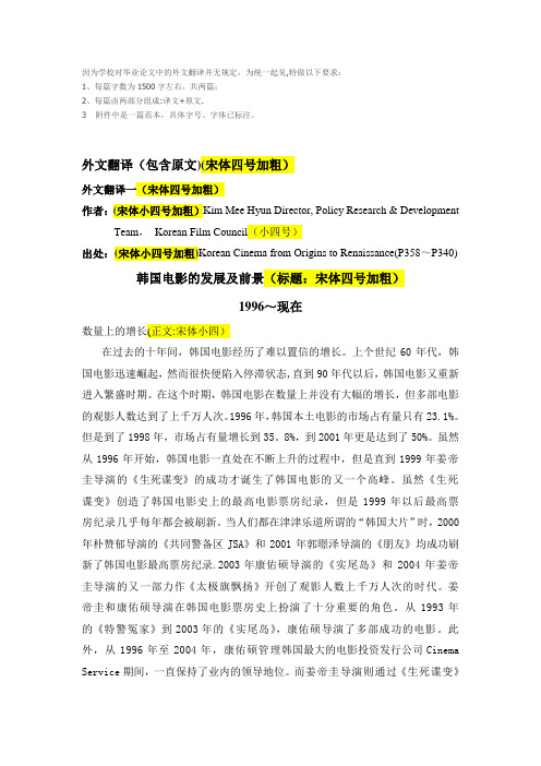
因为学校对毕业论文中的外文翻译并无规定,为统一起见,特做以下要求:1、每篇字数为1500字左右,共两篇;2、每篇由两部分组成:译文+原文.3 附件中是一篇范本,具体字号、字体已标注。
外文翻译(包含原文)(宋体四号加粗)外文翻译一(宋体四号加粗)作者:(宋体小四号加粗)Kim Mee Hyun Director, Policy Research & Development Team,Korean Film Council(小四号)出处:(宋体小四号加粗)Korean Cinema from Origins to Renaissance(P358~P340) 韩国电影的发展及前景(标题:宋体四号加粗)1996~现在数量上的增长(正文:宋体小四)在过去的十年间,韩国电影经历了难以置信的增长。
上个世纪60年代,韩国电影迅速崛起,然而很快便陷入停滞状态,直到90年代以后,韩国电影又重新进入繁盛时期。
在这个时期,韩国电影在数量上并没有大幅的增长,但多部电影的观影人数达到了上千万人次。
1996年,韩国本土电影的市场占有量只有23.1%。
但是到了1998年,市场占有量增长到35。
8%,到2001年更是达到了50%。
虽然从1996年开始,韩国电影一直处在不断上升的过程中,但是直到1999年姜帝圭导演的《生死谍变》的成功才诞生了韩国电影的又一个高峰。
虽然《生死谍变》创造了韩国电影史上的最高电影票房纪录,但是1999年以后最高票房纪录几乎每年都会被刷新。
当人们都在津津乐道所谓的“韩国大片”时,2000年朴赞郁导演的《共同警备区JSA》和2001年郭暻泽导演的《朋友》均成功刷新了韩国电影最高票房纪录.2003年康佑硕导演的《实尾岛》和2004年姜帝圭导演的又一部力作《太极旗飘扬》开创了观影人数上千万人次的时代。
姜帝圭和康佑硕导演在韩国电影票房史上扮演了十分重要的角色。
从1993年的《特警冤家》到2003年的《实尾岛》,康佑硕导演了多部成功的电影。
毕业论文 外文翻译格式

毕业论文外文翻译格式毕业论文外文翻译格式在撰写毕业论文时,外文翻译是一个重要的环节。
无论是引用外文文献还是翻译相关内容,都需要遵循一定的格式和规范。
本文将介绍一些常见的外文翻译格式,并探讨其重要性和应用。
首先,对于引用外文文献的格式,最常见的是使用APA(American Psychological Association)格式。
这种格式要求在引用外文文献时,先列出作者的姓氏和名字的首字母,然后是出版年份、文章标题、期刊名称、卷号和页码。
例如:Smith, J. D. (2010). The impact of climate change on biodiversity. Environmental Science, 15(2), 145-156.在翻译外文文献时,需要注意保持原文的准确性和完整性。
尽量避免意译或添加自己的解释,以免歪曲原文的意思。
同时,还需要在翻译后的文献后面加上“译者”和“翻译日期”的信息,以便读者可以追溯翻译的来源和时间。
其次,对于翻译相关内容的格式,可以参考国际标准组织ISO(International Organization for Standardization)的格式。
这种格式要求在翻译相关内容时,先列出原文,然后是翻译后的文本。
例如:原文:The importance of effective communication in the workplace cannot be overstated.翻译:工作场所有效沟通的重要性不容忽视。
在翻译相关内容时,需要注意保持原文的意思和语气。
尽量使用准确的词汇和语法结构,以便读者能够理解和接受翻译后的内容。
同时,还需要在翻译后的文本后面加上“翻译者”和“翻译日期”的信息,以便读者可以追溯翻译的来源和时间。
此外,对于长篇外文文献的翻译,可以考虑将其分成若干章节,并在每个章节前面加上章节标题。
这样可以使读者更容易理解和阅读翻译后的内容。
(范例)外文翻译格式

本科毕业设计(论文)外文翻译译文学生姓名:院(系):经济管理学院专业班级:市场营销0301班指导教师:完成日期:2007年3 月22 日日本的分销渠道——对于进入日本市场的挑战与机会Distribution Channels in JapanChallenges and Opportunities for theJapanese Market Entry作者:Hokey Min起止页码:P22-35出版日期(期刊号):0960-0035出版单位:MCB Univercity Press外文翻译译文:介绍尽管美国对日本的出口在过去两年已有大幅度的增长,然而美国对日本仍然存在着很大的贸易赤字。
尽管没有出现下降趋势,但越来越多的美国决策者及商务经理已经开始审查日本的贸易活动。
在这些人中,有一个很普遍的想法就是日本市场没有对美国产品开放,相反,美国市场对日本的贸易是开放的。
因此,克林顿政府试图采取强硬措施来反对日本的一系列贸易活动,包括商业习惯和政府政策,还企图通过贸易制裁的威胁来反对日本产品。
然而,这样的措施也会产生适得其反的结果。
它不仅会为美国消费者带来更高的商品价格和更少的商品选择,同时也会增加日本消费者的反美情绪。
最近Ginkota和Kotabe的调查表明:单独的贸易谈判不会提高美国商品进入日本市场的能力。
而对于提高美国公司进入日本市场能力的一个行之有效的方法就是研究日本近几个世纪以来所采用的商业活动。
由于法律障碍或者是日本公司对外封锁商业渠道,日本当地的分销渠道往往对外国公司不利,而这样的商业活动被认为是进入日本市场的主要障碍。
事实上,Yamawaki美国商品成功出口到日本市场在很大程度上取决于美国解决协议合同的能力。
尽管进入日本市场意义重大,然而对西方人而言,日本的经销体系经常会被人误以为是充满神秘感的。
这种误解源于日本复杂的分销惯例特征。
而这种分销惯例沿袭古老的而又严谨的建设体系。
在尝试美国贸易在日本市场成功获利减少不必要的贸易冲突过程中,我们揭露了日本分销中获利的事实,探索出了能成功进入日本市场的战略性武器。
外文翻译的格式样式

外文翻译格式样式
标题(黑体小二加粗居中)
(宋体小四空一行)
外文作者署名(楷体小四号居中)
(宋体小四空一行)
1 内容(黑体三号加粗)
1.1内容(黑体四号加粗)
边坡是地壳表部一切具有临空面的地质体,具有一定的坡度和高度,包括人工边坡、自然边坡以及崩滑体。
在重力、风化、侵蚀和其它地质作用下,边坡不断地发生变化,应力重新分布,并且随着边(宋体小四号)……
说明:以上为外文翻译的格式,译文前应附有被翻译的外文原件复印件,为了反映文稿的科学依据和译者尊重他人研究成果的严肃态度及向读者提出有关信息的出处,要求译者按著录/题名/出版事项顺序排列注明,请同学们遵照执行。
期刊:著者,题名,期刊名称,出版年,卷号(期号),起始页码。
书籍:著者,书名、版次(第一版不标注),出版地,出版者,出版年,起始页码。
毕业论文外文翻译格式【范本模板】

盐城师范学院毕业论文(设计)外文资料翻译学院:(四号楷体_GB2312下同)专业班级:学生姓名:学号:指导教师:外文出处:(外文)(Times New Roman四号) 附件: 1.外文资料翻译译文; 2.外文原文1.外文资料翻译译文译文文章标题×××××××××正文×××××××××××××××××××××××××××××××××××××××××××××××××××××××××××××××××………….*注:(本注释不是外文翻译的部分,只是本式样的说明解释)1. 译文文章标题为三号黑体居中,缩放、间距、位置标准,无首行缩进,无左右缩进,且前空(四号)两行,段前、段后各0.5行间距,行间距为1。
25倍多倍行距;2. 正文中标题为小四号,中文用黑体,英文用Times New Roman体,缩放、间距、位置标准,无左右缩进,无首行缩进,无悬挂式缩进,段前、段后0。
5行间距,行间距为1.25倍多倍行距;3。
正文在文章标题下空一行,为小四号,中文用宋体,英文用Times New Roman体,缩放、间距、位置标准,无左右缩进,首行缩进2字符(两个汉字),无悬挂式缩进,段前、段后间距无,行间距为1。
3-外文翻译模板格式及要求
杭州电子科技大学毕业论文外文文献翻译要求根据《普通高等学校本科毕业设计(论文)指导》的内容,特对外文文献翻译提出以下要求:一、翻译的外文文献可以是一篇,也可以是两篇,但总字符要求不少于1.5万(或翻译成中文后至少在3000字以上)。
二、翻译的外文文献应主要选自学术期刊、学术会议的文章、有关著作及其他相关材料,文献作者最好为国外的专家或学者;应与毕业论文(设计)主题相关,并作为外文参考文献列入毕业论文(设计)的参考文献。
并在每篇中文译文首页用“脚注”形式注明原文作者及出处,中文译文后应附外文原文。
脚注的方法:插入----引用---脚注和尾注三、中文译文的基本撰写格式为:1.题目:采用小三号、黑体字、居中打印,段前段后1行间距;;2.正文:采用小四号、宋体字,行间距为固定值20磅,标准字符间距。
页边距为左3cm,右2.5cm,上下各2.5cm,页面统一采用A4纸。
英文原文如为word文档,请用罗马字体排版,段前空两格,段间距20磅。
页眉为“杭州电子科技大学本科毕业论文外文翻译”,5号宋体字从正文开始编写页码,页码居中。
四、封面格式由学校统一制作(注:封面上的“翻译题目”指中文译文的题目),填充内容为加粗小三号楷体_GB2312,并按“封面、译文一、外文原文一、译文二、外文原文二、考核表”的顺序统一装订。
五、忌自行更改表格样式,学号请写完整。
封面和考核表均为一页纸张,勿换行换页。
注意:1.除了封面和考核表之外,外文翻译有页眉和页码。
2.外文翻译中各级标题统一为段前空两格;若标题无序号,也可按与原文一致的原则处理。
题目段前段后1行一级标题小四宋体加黑,段前段后0.5行其他各级标题段前空两格,小四宋体不加黑,其他与正文要求一致。
毕业论文外文文献翻译毕业设计(论文)题目Xxx(单击此处添加论文题目)翻译(1)题目指翻译后的第一篇中文译文的题目翻译(2)题目指翻译后的第二篇中文译文的题目若无,则本栏留空学院经贸学院专业国际经济与贸易(单击此处添加专业)姓名XXXXXX(单击此处添加姓名)班级XX020811(单击此处添加班级)学号XX023101(单击此处添加班级)指导教师XXXXXX(单击此处添加指导教师)单击此处添加翻译后的第一篇中文译文的题目1 [单击此处添加译文正文]一、单击此处添加一级标题1[单击此处添加译文正文]1.[单击此处添加译文正文]2.[单击此处添加译文正文]3.[单击此处添加译文正文]二、单击此处添加一级标题2[单击此处添加译文正文]1.[单击此处添加译文正文]2.[单击此处添加译文正文]3.[单击此处添加译文正文]三、单击此处添加一级标题3……………………………以下是模板的使用方法说明文字,正式成文后请删除。
外文翻译标准格式
毕业设计(论文)
译文及原稿译文题目:[单击此处添加译文题目]
原稿题目:[单击此处添加原稿题目]
原稿出处:[单击此处添加原稿出处]
[单击此处添加译文题目]
[单击此处添加译文正文]
以下是说明文字,正式成文后请删除。
1、模板的使用方法
(1)请不要删除任何具有格式的模板文字。
(2)按照提示直接单击或单击后选择“编辑”→“选择性粘贴”—“无格式文本”就可添加相应内容。
2、在“原稿出处”中对原稿的来源进行说明,包括作者姓名、出处、出版信息等。
期刊类文献书写方法:作者(不超过3人,多者用“等”或“et al”表示).题名[J].刊名,出版年,卷号(期号):起止页码.
论文集类文献书写方法:著者.题名[C].编者.论文集名.出版地:出版社,出版年份:起止页码.
有一篇译文,按如下顺序列出:
译文题目一
原稿题目一
原稿出处一
3、检索和利用外文资料的能力是现阶段毕业设计(论文)环节中所要求掌握的基本能力之一。
外文翻译是在查阅外文文献时,将篇幅适当、内容与选题相关的外文资料翻译成中文。
通过翻译外文资料,可更深层次地了解国外相关领域的现状,同时也是对翻译能力的锻炼,并为考察和检验学生外语能力提供依据。
4、进行外文翻译应注意以下几点:
(1)翻译的外文文献内容应与论文选题相关;一般应选自国外学术期刊、学术会议的文章及其他相关材料。
(2)篇幅、深度和难度适当,可以由1篇文章组成。
5、外文翻译字符应达到2000字符。
[单击此处添加外文原稿题目] [单击此处添加外文原稿正文]。
外文翻译格式说明
山东理工大学毕业设计(外文翻译材料)学院:专业:学生姓名:指导教师:电气与电子工程学院自动化于小涵季画外文翻译材料格式要求:1.页边距:上3.8磅;下3.8磅;左3.2,右3.2;页眉距边界2.8,页脚距边界32.原文题目:Arial,小三;间距:段前18磅,段后12磅,间距21磅3.原文正文:Times New Roman,小四;间距:段前0磅,段后6磅,间距21磅4.译文题目:黑体,小三;间距:同原文题目5.译文正文:宋体,小四;间距同原文正文6.页眉页脚:原文页眉处写:外文翻译(原文),宋体,五号。
译文页眉处写:外文翻译(译文),宋体,五号。
原文译文的页脚统一编页码(不要单独编页码)。
Plant Model Generation for PLC SimulationHyeong-Tae ParkAbstract:This paper reports an automated procedure for constructing a plant model for PLC simulation. Since PLC programs contain only the control logic without information on the plant model, it is necessary to build the corresponding plant model to perform the simulation. Conventionally, a plant model for PLC simulation has been constructed manually, which requires much effort and indepth knowledge of the simulation. As a remedy for this problem, we propose an automated procedure for generating a plant model from the symbol table of a PLC program. To do so, we propose a naming rule for PLC symbols so that the symbol names include sufficient information on the plant model. By analysing such symbol names, we extract a plant model automatically. The proposed methodology has been implemented and test runs performed.Keywords: agile manufacturing; CAD/CAM; CAPP; simulation1. IntroductionTo survive and prosper in the modern manufacturing era, manufacturers need to continuously improve their products, as well as their production systems. A modern manufacturing line is a highly integrated system composed of automated workstations, such as robots with tool-changing capabilities, a hardware handling system and storage system, and a computer control system that controls the operations of the- 1 -entire system.Since the implementation of a manufacturing line requires heavy investment, proper verification of a line’s operational status sho uld be performed to ensure that the highly automated manufacturing system will successfully achieve the intended benefits. Simulation technology is considered to be an essential tool in the design and analysis of complex systems that cannot be easily described by analytical or mathematical models . Simulation is useful for calculating utilisation statistics, finding bottlenecks, pointing out scheduling errors, and even for creating manufacturing schedules. Traditionally, various simulation languages, including ARENA and AutoMod, have been used for the simulation of manufacturing systems. These simulation languages have been widely accepted both by industry and by academia; however, they remain as analysis tools for the rough design stage of a production line, because their simulation models are not sufficiently realistic to be utilised for a detailed design or for implementation purposes. For example, real production lines are usually controlled by PLC (Programmable Logic Controller) programs (Rullan 1997), but conventional simulation languages roughly describe the control logic with independent entity flows (job flows) between processes.- 2 -Production systems typically consist of simultaneously operating machines, which are controlled by PLCs, currently the most suitable and widely employed industrial control technology. A PLC emulates the behaviour of an electric ladder diagram. As they are sequential machines, to emulate the workings of parallel circuits that respond instantaneously, PLCs use an input/output symbol table and a scanning cycle. When a program is being run in a PLC it is continuously executing a scanning cycle. The program scan solves the Boolean logic related to the information in the input table with that in the output and internal relay tables. In addition, the information in the output and internal relay tables is updated during the program scan. In a PLC, this Boolean logic is typically represented using a graphical language known as a ladder diagram (IEC 2003).Since the abstraction levels of conventional simulators and PLC programs are quite different, the control logic of conventional simulators cannot be reused for the generation of PLC programs. Usually, electrical engineers manually write PLC programs by referring to the rough control logic of conventional simulators, as shown in Figure 1. Since PLC programming is a very tedious and error-prone job, it is essential to verify the PLC programs offline to reduce the stabilisation time of a production system.Previous approaches to a PLC program can be categorised into two groups:- 3 -(1) verification of a given PLC programand (2) generation of a dependable PLC program. In the first group, various software tools have been developed for the verification of PLC based systems via the use of timed automata, such as UPPAAL2k, KRONOS, Supremica and HyTech, mainly for programs written in a statement list language, also termed Boolean (Manesis and Akantziotis 2005). Such software tools verify PLC programs to a certain extent; however, they remain limited. Since they mainly focus on the checking of theoretical attributes (safety, liveness, and reachability), it is not easy for users to determine whether the PLC programs actually achieve the intended control objectives. In the second group, many researchers have focused on the automatic generation of PLC programs from various formalisms including state diagrams, Petri nets, and IDEF0. These formalisms can help the design process of control logics; however, it is still difficult to find hidden errors, which is the most difficult part of verifying a control program.Figure 2. The concept of PLC simulation.To overcome the aforementioned problems, it is necessary to utilise simulation techniques for PLC program verification. By simulating PLC programs, it is possible to analyse the control logic in various ways and recognise hidden errors more intuitively (David 1998). Although PLC simulation can be a very powerful tool for the detailed verification of a production system, the accompanying construction of a plant model is a major obstacle (the counterpart model of a control program). Since PLC programs only contain the control information, without device models, it is necessary to build a corresponding plant model to perform simulation, as shown in- 4 -Figure 2. However, constructing a plant model requires an excessive amount of time and effort. Sometimes, the plant model construction requires much more time than the PLC programming. This serves as the motivation for exploring the possibility of finding an automatic procedure for generating a plant model from a given PLC program.Figure3.Symbol table of a PLC program.Although the objective of a PLC program is not to describe a plant model (device models), the symbol table of a PLC program can provide a glimpse of the plant model. As shown in Figure 3, symbols in a PLC program usually contain some information related to the plant. For example, ‘EXLINE_MB_AGV_P1’ means that the symbol is a signal that is related to the control of an ‘AGV’ (Auto Guided Vehicl e) belonging to the ‘MB’ station of ‘EXLINE’ line. The above scenario reveals the key idea of the present study. If we can develop a proper naming rule for PLC symbols, then it might be possible to extract a plant model by analysing the symbol names.This paper has two major objectives: (1) to propose a proper naming rule for PLC symbols and (2) to develop a procedure for generating a plant model by analysing the symbol names. The application area of the proposed methodology includes all types of automated manufacturing systems controlled by PLC programs, such as automotive production lines, FMSs (flexible manufacturing systems), and ASRSs (automatic storage and retrieval systems). The overall structure of the paper is as follows. Section 2 addresses the specifications of a plant model for PLC simulation. Section 3 describes a naming rule for PLC symbols, which enables the automatic generation of a plant model. Finally, concluding remarks are given in Section 4.2. Plant model for PLC simulationBefore explaining the specification of a plant model enabling PLC simulation, we want to address the importance of the PLC simulation. Chuang et al. (1999) proposed a procedure for the development of an industrial automated production system that- 5 -- 6 -consists of nine steps, as follows: (1) define the process to be controlled; (2) make a sketch of the process operation; (3) create a written sequence of the process; (4) on the sketch, add the sensors needed to carry out the control sequence; (5) add the manual controls needed for the process setup or for operational checks; (6) consider the safety of the operating personnel and make additions and adjustments as needed;(7) add the master stop switches required for a safe shutdown; (8) create a ladder logic diagram that will be used as a basis for thePLC program; and (9) consider the possible points where the process sequence may go astray. The most time-consuming task for the control logic designers is the eighth step, which is usually done by the repetitive method of code writing, testing, and debugging until the control objectives are achieved (Manesis and Akantziotis 2005). This is the reason why conventional PLC programming is often inefficient and prone to human error. As the configurations of production lines and their control programs become more complicated, there is a strong need for a more efficient PLC simulation environment. It is hoped that this paper will take positive steps in this direction.A PLC can be considered as a dedicated computer system having input and output signals. To run a PLC, the corresponding plant model (the counterpart system) is required to interact with the input and output of the PLC. The behaviour of the plant model should be the same as that of the actual system to achieve PLC verification. Since a production line consists of various devices, including robots, transporters, jigs, solenoids, proximity sensors, and light sensors (Groover 2006), we can consider a plant model as a set of device models. To build such a device model, this paper em ploys Zeigler’s DEVS (Discrete Event Systems Specifications) formalism (Zeigler 1984, Kim 1994), which supports the specification of discrete event models in a hierarchical, modular manner. The semantics of the formalism are highly compatible with object-oriented specifications for simulation models. We use the atomic model of the DEVS formalism to represent the behavior of a device model. Formally, an atomic model M is specified by a 7-tuple:M =〈X, S,Y, sin δ,ext δ,λ ,t a 〉X input events setS sequential states setY output events setsin δ S→S: internal transition functionext δQ*X→S: external transition functionQ={(s, e)∣s ∈S, 0≤e ≤t a (s)}: total state of MλS →Y: output function- 7 -t a S →Real: time advance functionThe four elements in the 7-tuple, namely sin δ,ext δ,λand t a , are called the characteristic functions of an atomic model. The atomic model of the DEVS formalism can be considered as a timed-FSA (finite state automata), and it is suitable for describing the behaviour of a device model. Once the device models (plant model) are obtained, it becomes possible to perform the PLC simulation. Currently, device models should be construed manually, which takes much time and effort. To cope with the problem, the objective of the paper is to propose an automated generation procedure for device models.Before explaining the automatic generation procedure of a plant model, let us take a look at the manual procedure to construct device models. To construct a device model, first it is necessary to identify the set of tasks that are assigned to the device. The activation of each task is normally triggered by an external signal from PLC programs. Once the set of tasks is identified for a device, it is then possible to extract the state transition diagram, which defines an atomic model of the DEVS formalism. Figure 4(a) shows a simple example of an AGV (Automatic Guided Vehicle) with two tasks, T1 (movement from p1 to p2) and T2 (movement from p2 to p1). As the two tasks should be triggered by external events, the shell part of the AGV must have two input ports, termed here as Signal_1 and Signal_2, as shown in Figure 4(b).From the set of tasks, it is possible to instantiate the state transition diagram. For this example, there are four states, P1, DoT1, P2 and DoT2. While P1 and P2 take external events from the input ports (Signal_1, Signal_2) for state transitions, DoT1 and DoT2 take internal events that are the end events of the two tasks (T1 and T2). The DEVS atomic model of the virtual device, corresponding to the AGV, can be described as follows:- 8 -Shell of a virtual device:M=〈X,S,Y,sin δ,ext δ,λ ,t a 〉}2_,1_{Signal Signal =X S={P1,DOT1,P2,DOT2} Y={T1Done,T2Done}sin δ(DOT1)=P2 s i nδ(DOT2)=P1 ext δ(P1,Signal_1)=DOT1 ext δ(P2,Signal_2)=DOT2λ(DOT1)=T1Done λ(DOT2)=T2Donet a (DOT1)=Time_1 t a (DOT2)=Time_2Once a plant model has been constructed, it is possible to perform the PLC simulation, which enables the intuitive verification of a PLC program. Figure 5 shows the connections between a PLC program and a plant model. The plant model includes all device models of a production system, and the PLC program contains the control logic for the plant model. To integrate the plant model and the PLC program, it is necessary to define the mapping between the plant model and the PLC program, which is described by I/O mapping. To enable the visual verification of a PLC program, it is necessary to import 3D graphic models, which are controlled by the logical device models (the state transition diagrams). Since 3D graphic models are not always necessary, they are optional for PLC simulation. As mentioned already, the objective of this paper is to extract device models from the symbol names of PLC programs. To do so, it is necessary to develop a proper naming rule for PLC symbols. The naming rule will be addressed in the next section.3. Symbol naming for plant model generationAlthough IEC 61131-3 provides various standard specifications for a PLC, the naming rules of PLC symbols have rarely been brought into focus. Since there have been no standard rules for the naming of PLC symbols, it has been fully dependent on individual PLC programmers.To generate device models from PLC symbols, it is necessary to make PLC symbols that include enough information concerning the plant model. To achieve this objective, we interviewed many PLC programmers and analysed various conventional rules. As a result, we came up with a naming structure consisting of five fields: (1) line name, (2) process number, (3) device name, (4) input or output, and (5) task name (or state name). Figure 6 shows the naming structure for PLC symbols.If the PLC symbols are named according to the proposed naming structure, then it becomes possible to extract device models (atomic models of DEVS formalism) by simply analysing the symbol names. There are two types of symbols (signals), input or output, which are specified by the fourth field. The purpose of the output signal is to trigger a task that is specified by the fifth field. Thus, it is possible to identify the set of tasks of a device by analysing the output symbols. As mentioned already, once the set of tasks is identified for a device, it is then possible to extract the state transition diagram for the device model, which defines an atomic model of the DEVS formalism. While an output signal (symbol) is issued by a PLC to trigger a task, an input signal (symbol) is issued by a device to report the completion of the task to theδand internal transition functions PLC. This means that external transition functionsextδof a device model can be automatically extracted from the output and input sinsymbols, respectively. We demonstrate the generation procedure of a plant modelfrom PLC symbols using an example, as shown in Figure 7.- 9 -- 10 -In the example cell, we assume a part is loaded manually on the AGV by a worker. When the AGV senses the existence of a part, it moves to transfer the part to the machine. After the transfer, the machine performs machining to convert the part into a finished product. In this case, the plant model consists of two device models: an AGV model and a machine model. The PLC program to control the simple manufacturing cell is shown in Figure 8(a), and its symbol table is shown in Figure 8(b).As shown in Figure 8(b), the AGV model has two output symbols and two input symbols. From the output symbols (EX_OP_AGV_O_GOP1, EX_OP_AGV_O_GOP2), we can intuitively recognise that the AGV has two tasks- 11 -(movement from P2 to P1, and movement from P1 to P2). By using the output symbols, we can extract the state transition diagram, as well as the external transitionfunctions, as shown in Figure 9(a).As mentioned already, an output symbol triggers a task of a device model, and an input symbol is made by the device to notify the completion of the task. Since the execution of a task is performed internally by the device, the internal transition functions of a device model can easily be extracted from the input symbols(EX_OP_AGV_I_DONEGOP1, EX_OP_AGV_I_DONEGOP2). In this way, the device model of the machine can be extracted from the related symbols(EX_OP_MC_, etc.), as shown in Figure 9(b). The procedure for the construction of a device model can be described as follows.- 12 -(1) Identify all corresponding pairs between output symbols and input symbols. While an output symbol triggers a task, the corresponding input symbol reports the completion of the task. For example, EX_OP_AGV_O_GOP1 corresponds toEX_OP_AGV_I_DONEGOP1. (2) Define the states of a device mode using the last naming fields of input/output symbols. In the case of the AGV, we can define four states, GoP1, DoneGoP1, GoP2, and DoneGoP2. (3) Define external (internal) transition functions using output (input) symbols. Once a plant model has been obtained, it becomes possible to perform the PLC simulation by defining the I/O mapping relations between the plant model and the PLC symbols. Through the PLC simulation, we can efficiently check whether the PLC program achieves the control objectives or not.The proposed methodology was implemented in C++language, and test runs were made on a personal computer, as shown in Figure 10. The PLC program shown in Figure 8(a) was written using GX IEC developer version 7.0 provided byMitsubishi Electric Corporation. The GX IEC developer can export a symbol table in the form of an Excel file, as shown in Figure 8(b). The exported symbol table becomes the input for the generation of a plant model. Figure 10 shows that the generated device models by analysing the exported symbol table.4. Discussion and conclusionsThrough PLC simulation, it is possible to analyse control logic in various ways and recognise hidden errors more intuitively. Although PLC simulation can be a very powerful tool for the detailed verification of a production system, the accompanying construction of a plant model requires too much time and effort. To remedy this problem, we have proposed an automated procedure to generate a plant model from the symbol table of a PLC program. To do so, we have also proposed a naming rule for PLC symbols so that the symbol names include sufficient information on the plant model. By analysing the symbol names, a plant model can be extracted automatically. Since a plant consists of various manufacturing devices, we can consider a plant model as a set of device models. To represent such a device model, the proposed method employs Zeigler’s DEVS formalism. We use the atomic model of the DEVS formalism to describe the logical behavior of a device model. In other words, it is necessary to extract the device models from the symbol table in the form of an atomic model of the DEVS formalism. Although the proposed methodology only deals with the local verification of PLC programs, it is also possible to extend the methodologyto include the verification of mechanical aspects of the plant .- 13 -工厂模型生成PLC仿真Hyeong-Tae Park摘要 :本文介绍一个自动程序可编程序控制器(PLC)生成工厂模型仿真。
外文翻译及外文原文(参考格式)
外文翻译要求:1、外文资料与毕业设计(论文)选题密切相关,译文准确、质量好。
2、阅读2篇幅以上(10000字符左右)的外文资料,完成2篇不同文章的共2000汉字以上的英译汉翻译3、外文资料可以由指导教师提供,外文资料原则上应是外国作者。
严禁采用专业外语教材文章。
4、排序:“一篇中文译文、一篇外文原文、一篇中文译文、一篇外文原文”。
插图内文字及图名也译成中文。
5、标题与译文格式(字体、字号、行距、页边距等)与论文格式要求相同。
下页附:外文翻译与原文参考格式2英文翻译 (黑体、四号、顶格)外文原文出处:(译文前列出外文原文出处、作者、国籍,译文后附上外文原文)《ASHRAE Handbook —Refrigeration 》.CHAPTER3 .SYSTEM Practices for ammonia 3.1 System Selection 3.2 Equipment3.10 Reciprocating Compressors第3章 氨制冷系统的实施3.1 系统选择在选择一个氨制冷系统设计时,须要考虑一些设计决策要素,包括是否采用(1)单级压缩(2)带经济器的压缩(3)多级压缩(4)直接蒸发(5)满液式(6)液体再循环(7)载冷剂。
单级压缩系统基本的单级压缩系统由蒸发器、压缩机、冷凝器、储液器(假如用的话)和制冷剂控制装置(膨胀阀、浮球阀等)。
1997 ASHRAE 手册——“原理篇”中的第一章讨论了压缩制冷循环。
图1.壳管式经济器的布置外文翻译的标题与译文中的字体、字号、行距、页边距等与论文格式相同。
英文原文(黑体、四号、顶格)英文翻译2(黑体,四号,顶格)外文原文出处:(黑体,四号,顶格)P. Fanning. Nonlinear Models of Reinforced and Post-tensioned Concrete Beams. Lecturer, Department of Civil Engineering, University College Dublin. Received 16 Jul 2001.非线形模型钢筋和后张法预应力混凝土梁摘要:商业有限元软件一般包括混凝土在荷载做用下非线性反应的专用数值模型。
- 1、下载文档前请自行甄别文档内容的完整性,平台不提供额外的编辑、内容补充、找答案等附加服务。
- 2、"仅部分预览"的文档,不可在线预览部分如存在完整性等问题,可反馈申请退款(可完整预览的文档不适用该条件!)。
- 3、如文档侵犯您的权益,请联系客服反馈,我们会尽快为您处理(人工客服工作时间:9:00-18:30)。
重庆科技学院学生毕业设计(论文)外文译文学院建筑工程学院专业班级土木应08(3)学生姓名谭梳琪学号2008540402译文要求1.外文翻译必须使用签字笔,手工工整书写,或用A4纸打印。
2.所选的原文不少于10000印刷字符,其内容必须与课题或专业方向紧密相关,由指导教师提供,并注明详细出处。
3.外文翻译书文本后附原文(或复印件)。
外文原文出自:R.帕克、T.波利编著的《钢筋混凝土结构》中的417-423页7.4 有腹筋钢筋混凝土梁的抗剪机理7.4.1腹筋的作用梁内有了像箍筋这样的腹筋之后,不会从根本上改变前面所描述的抗剪机理。
作为梁作用的主要元件的混凝土悬臂这时将像被拉住的悬臂那样工作。
除去有骨料咬合、销栓和悬臂的弯曲作用所联合承担的粘结力ΔT之外,还有一部分粘结力ΔT′能够由习惯上所说的“桁架作用”来承担。
在这个桁架中,悬臂起斜向压杆的作用(见图7.14)。
图7.14 起斜压杆作用的混凝土悬臂箍筋的存在在其他许多方面对梁作用也是有益的,它通过以下方式对抗剪机构的强度发挥作用:1.改进销栓作用。
箍筋能够有效地支承在它附近与弯剪裂缝相交的纵向钢筋。
2.通过桁架作用产生的斜压力C d抵消悬臂块体内的弯曲拉应力。
3.限制斜裂缝在弹性范围内的张开程度,从而使由骨料咬合作用传递的剪力得以维持和增强。
4.当箍筋布置得足够密时,能对混凝土提供约束,从而特别是在受拱作用影响的部位提高其抗压强度。
5.当在锚固区内由于销栓力和锚固力的作用而形成劈裂裂缝时,能防止粘结遭到破坏。
总之,可以说,做了适当的细部设计的腹筋将能保持梁的整体性,并因而能够保持前面已经详述的梁机构的强度V e,从而使更多的建立V s能由桁架机构来承担。
7.4.2桁架机构一个平行弦桁架与一个有腹筋混凝土梁之间在抗剪作用方面的相似性是混凝土结构的一个古老的概念。
这种由Morsch[7.2.23]在本世纪初所假定的相似性的含义是,等效桁架的腹杆是由起拉杆作用的箍筋和走向平行于斜裂缝的、通常是与梁轴成45°角的混凝土压杆所组成的。
混凝土的弯曲受压区和弯曲受拉钢筋构成这种比拟铰接桁架的上弦和下弦。
桁架的内力只需根据平衡条件就能确定。
这个桁架的性能与前已详述的“理想梁作用”相似到了如此地步,以至它能承受分散于弯曲受拉钢筋方向上的各个虚拟铰接点处的粘结力ΔT′,从而以不变的内力偶臂长来抵抗变化的外弯矩。
在梁内伴随着梁作用或拱作用以及桁架机构而出现的变形之间是不协调的。
这种按惯例不予考虑的应变不协调性在趋近极限(即塑形)状态时越来越不显著。
图7.15中的比拟桁架描绘了腹筋以β角倾斜于水平线的一般情况。
它也可以用来表示有桁架所承担的外剪力V s与各内力之间的关系。
承受压力的C s的斜压杆与水平线的交角为α。
由图7.15中所绘节点X的平衡力多边形显然可见:式中Ts为所有穿过斜裂缝的箍筋内力之和。
腹筋在单位梁长内承受的力为T s/s,其中s为箍筋间距,其值按比拟桁架的几何关系应为:由公式7.18和7.19可得单位长度上箍筋的内力为:式中Av为沿梁长按间距为s布置的腹筋的截面面积,fx为箍筋应力。
图7.15 比拟桁架中的内力从设计应用来看,像在共事7.15中那样用名义应力来表示建立是比较方便的。
总剪力V u是假定为一部分由桁架机构来承受(V s),另一部分由前面描述的梁机构或拱机构来承受(V c)。
这一关系如用应力表示即为:式中将公式7.20与共事7.22结合起来,则当fs=fy时按理想强度所需的腹筋面积为:现假定斜压力C d在桁架压杆中产生均匀应力。
压杆的有效高°为s′=s sinα=jdsinα(ctgα+ctgβ)。
于是,由桁架机构产生的斜压应力可以近似地表示为:对于常见的腹筋布置情况,公式7.23和7.24便简化如下:1.垂直箍筋,β=90°当斜压杆倾角α=45°时当斜压杆倾角α=30°时2.斜置腹筋,β<90°当斜压杆倾角α=45°时当腹筋及压杆倾角均为45°时斜压杆的坡度按照惯例都是假设与梁轴成45°的。
但是已经观测到,在压杆边界处的斜裂缝倾角是沿梁长变化的。
以应变能原理为基础所做的研究[7.24]表明,压杆的最优倾角大约为38°。
从公式7.23可以明显看出,当斜压杆的倾角变为小于45°时,由于有较多的箍筋穿过坡°平缓的裂缝,腹筋的需要量就会减少。
实际情况往往都是这样的,因而按斜压杆倾角为45°的设计公式便是偏于保守的。
而另一方面,在何在作用点附近的斜压杆坡°却比较陡。
但是这些部位的局部拱作用可以增强其它抗剪机构的承载能力。
一般地说,在混凝土强度以及腹筋含量少,从而相当于受拉体系刚度较小的梁内,压杆的倾角小于45°,而这里的箍筋就比在压杆倾斜45°的桁架内更为有效。
反之,当梁的腹筋含量多而混凝土强度较低时,混凝土上的荷载就会以有较多的箍筋参与处理为代价而被减轻[7.24]。
在图7.16中展示了荷载作用点和反弯点附近斜裂缝的坡度。
平缓的斜压杆和坡度较陡的箍筋意味着混凝土的压应力比较大(参见公式7.24d和7.24b)。
这表明腹筋的含量不能无限制地增大。
图7.16表示一根配有大量腹筋的薄腹工字形截面连续梁。
在这种梁内由斜压引起的腹板压碎可以导致剪切破坏(公式7.24)。
在估计梁腹的抗压强度时,需要考虑下列另外一些因素:1.斜压杆在参与梁作用时还要承受弯矩(图7.7)。
由于桁架内没有真正的“铰接点”而引起了次弯矩。
2. 穿过斜压杆的箍筋通过粘结力把拉力传给斜压杆,以至于斜压杆往往普通出于双向应变状态。
我们知道,当同时作用有横向拉应变时,混凝土额抗压承载力会大为降低(图2.8)。
3. 压力是在比拟桁架的“节点”处引起的,而这些压力沿腹板远远不是均匀分布的。
因此就可能出现偏心及横向拉应力。
4. 有些斜杆的倾斜角°可能比45°小得多,这将导致斜压应力的显著增加(公式7.24和图7.16)这些观察结果表明,有必要把混凝土的斜压应力值限制在适当低于混凝土抗压强度值的范围内。
基于这一原因,ACI 就把桁架机构对抗剪强度所能起的作用限制为一个非常保守的数值f v c s '=8(psi )。
于是,按所取vc 值的大小即可由公式7.15和公式7.21得出梁内的绝对最大名义剪应力应为f v f ''c max ,u 5.1110<<以psi 为单位)。
然而Kupfer 和Baumann [7.24]等人曾指出。
当箍筋布置得像图7.16中的工字形截面预制混凝土梁一样密时,梁的名义剪应力甚至在以相当于v s 为f c '10的荷载强度作用50次之后还能达到f c '20这样的数量级。
但是在矩形截面梁中,这样大的剪应力通常是达不到的。
箍筋只是在它被充分锚固时才能发挥出给定的强度。
箍筋在其长度上的任何一点处都可能与斜裂缝相交。
由于斜裂缝有可能非常接近于构件的受拉或受压边缘,所以箍筋在它的整个长度内都必须能发挥出它的屈服强度。
因此,很重要的是必须把箍筋弯绕过较粗的纵向钢筋并再向前伸出一个足够的发挥长度。
各本规范都规定了能令人满意的各种锚固形式,为了使桁架作用显著,箍筋必须把荷载交代到“铰接点”或其附近。
像在第十三章中扼要叙述的那样,精心做出的细部构造设计能保证这种荷载传递。
如未能保证箍筋与纵向弯曲受拉钢筋的良好贴合,则在箍筋转交处由于荷载集中传递就可能导致混凝土的局部压碎。
已在一些构件中观测到了大到0.02in (0.5mm )的箍筋滑移。
如果是在浅梁中,这样大的滑移就能使斜裂缝宽度大为增加。
有时,与一条伸展的斜裂缝相交的一批箍筋都屈服了,那条裂缝就要开始展开变宽而不受约束,因而作为抗剪强度的一个重要组成部分的骨料咬合左右这时就会失去作用。
这样损失掉的抗剪强度是不可能转移到销栓和桁架机构上去的,因为它们的能力也已消耗殆尽了。
因此,当变形稍有增加时就会接着发生破坏。
为了防止这种非延性破坏,实践证明较好的办法是确保(这在抗震设计中实际上是强制性的)在构件的抗弯承载能力全部耗尽之前箍筋不要屈服。
梁的桁架机构只是在斜裂缝形成之后(即在混凝土内的斜拉力消失以后)才会起作用。
箍筋的主要作用只是横穿潜在的破坏性斜裂缝传递横向(垂直)剪力。
有热不时主张在梁的腹板内使用钢筋网。
它虽然既能承担水平力,又能承担垂直力,但是在抗剪方面并不是更为有效的。
这是因为在普通梁的梁腹中水平钢筋除了能帮助控制裂缝和增强销栓作用外并不能对承担横向(垂直)力发挥什么作用[7.20]。
水平腹筋能增强“混凝土提供的抗剪强度”v c ,但却影响不到桁架机构的抗剪强度v s (见公式7.21)。
然而对于深梁,正如在第十三章中将要探讨的,在支座区域内锚固良好的附加水平钢筋却能使拱作用显著增强。
图7.16 薄腹架中的裂缝形成情况[7.24]7.4.3 有腹筋梁的抗剪设计前面已经指出,只要裂缝宽度不是过大,无腹筋梁的抗剪机构,特别是骨料咬合作用就将继续起作用。
故在有腹筋情况下只要腹筋应变并不很大(即箍筋尚未屈服),“梁作用”就还是要承受剪力的。
所以,在箍筋屈服之前或开始屈服时,可以把这两种作用的强度如此叠加起来:公式7.15或公式7.16已经给出了ACI规定的偏于保守的v c值,这个数值实质上是混凝土关系示于图7.17中。
应当记住,在ACI的规定中是假定斜压杆的倾角α=45°的。
另一种可以采纳的观点[7.24]则认为混凝土提供的强度vc可以忽略不计,而且混凝土斜压杆的倾角是小于45°的,因此会有更多的箍筋跨过可能出现的裂缝(例如见图7.16)。
图7.17中的几条虚线表示了与众不同的α值相对应的关系曲线。
对于大多数梁来说,用这两种方法预测的抗剪强度是很接近的。
在图7.18中把按ACI的设计方法所得的计算结果与Leonhardt和Walther[7.7]试验的梁的受力性能做了对比。
可以看出,ACI低估了混凝土在极限荷载下所提供的强度v c。
图中用虚线表示的是改写成为f s=(v u-v c)/ρv来表示箍筋应力的理论关系式(公式7.23a),其中ρv=A v/sb w图7.18a把按ACI的方法所得的计算结果与四根腹筋相同的梁的试验结果作了比较。
这批梁只是腹板宽度有变化;翼缘宽度与腹板厚度之比在1到6之间变动。
因此可以预料混凝土提供的强度Vc将随腹板厚度的增加而成比例地增长(见公式7.15)。
这一推测已为试验所证实。
持此之外还可以看出,箍筋应力显著上升之前的剪力(前面称做引起斜裂缝的剪力)在箍筋朝屈服强度上升的过程中是保持不变的,即vc几乎保持常量。
4根相同的T 形截面梁[7.7]在图7.18中也显示出具有与此相同的性能,其中箍筋在总抗剪强度中所占的理论份额(η=v s/v u)是在27~93%之间变化的。
