乐普膜壳R8040B300S-00-10.1
WBP(S) Aquacoat Plus 水溶性保护胶水说明书
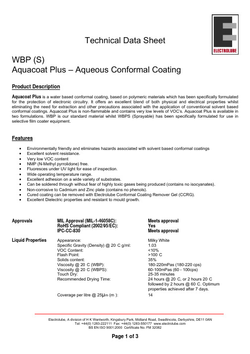
Technical Data SheetWBP (S)Aquacoat Plus – Aqueous Conformal CoatingProduct DescriptionAquacoat Plus is a water based conformal coating, based on polymeric materials which has been specifically formulated for the protection of electronic circuitry. It offers an excellent blend of both physical and electrical properties whilst eliminating the need for extraction and other precautions associated with the application of conventional solvent based conformal coatings. Aquacoat Plus is non-flammable and contains very low levels of VOC’s. Aquacoat Plus is available in two formulations. WBP is our standard material whilst WBPS (Sprayable) has been specifically formulated for use in selective film coater equipment.Features•Environmentally friendly and eliminates hazards associated with solvent based conformal coatings •Excellent solvent resistance. •Very low VOC content •NMP (N-Methyl pyrrolidone) free. •Fluoresces under UV light for ease of inspection. •Wide operating temperature range. •Excellent adhesion on a wide variety of substrates. •Can be soldered through without fear of highly toxic gases being produced (contains no isocyanates). •Non-corrosive to Cadmium and Zinc plate (contains no phenols). •Cured coating can be removed with Electrolube Conformal Coating Remover Gel (CCRG). •Excellent Dielectric properties and resistant to mould growth.Approvals MIL Approval (MIL-1-46058C): Meets approvalRoHS Compliant (2002/95/EC): YesIPC-CC-830 Meets approvalLiquid Properties Appearance: Milky WhiteSpecific Gravity (Density) @ 20°C g/ml: 1.03VOC Content: <10%Flash Point: >100°CSolids content: 35%Viscosity @ 20°C (WBP): 180-220mPas (180-220 cps)Viscosity @ 20°C (WBPS): 60-100mPas (60 - 100cps)Touch Dry: 25-35 minutesRecommended Drying Time: 24 hours @ 20°C, or 2 hours 20°Cfollowed by 2 hours @ 60°C. Optimum properties achieved after 7 days.Coverage per litre @ 25µm (m²):14Electrolube, A division of H K Wentworth, Kingsbury Park, Midland Road, Swadlincote, Derbyshire, DE11 0ANDry Film Coating Colour: Clear transparentOperating Temperature Range: -60°C to +125°CFlammability: Meets UL94-V1Thermal cycling (MIL-1-46058C): PassCoefficient of Expansion: 125 ppmDielectric Strength: 50 kV/mmDielectric Constant: 2.6Insulation Resistance: 5 x 10¹¹ Ohms/cmDissipation Factor @ 1MHz @ 25°C 0.03Moisture Resistance (MIL-1-46058C): PassPackagingDescription Order Code Shelf LifeConformal Coating 5 Litre Bulk WBP05L 12 MonthsConformal Coating (Sprayable) 5 Litre Bulk WBP05LS 12 MonthsDeionised Water Thinners 5 Litre DEI05L 36 MonthsRemoval Solvent 1 Litre Bulk CCRG01L 36 MonthsDirections For UseWBP can be sprayed, dipped or brushed. The thickness of the coating depends on the method of application (typically 25 microns). Temperatures of less than 16°C or relative humidity in excess of 75% are unsuitable for the application of WBP. Substrates should be thoroughly cleaned before coating. This is required to ensure that satisfactory adhesion to the substrate is achieved. Also, all flux residues must be removed as they may become corrosive if left on the PCB.Electrolube manufacture a range of cleaning products using both hydrocarbon solvent and aqueous technology. Electrolube cleaning products produce results within Military specification.Spraying – Bulk (WBP)WBP needs to be diluted with the appropriate thinners (DEI) before spraying. The optimum viscosity to give coating quality and thickness depends on the spray equipment and conditions, but normally a dilution ratio of 5:1 to 2:1 (WBP to DEI). Suitable spray viscosity is typically 50-80 centipoise. If bulk coating material has been agitated, allow to stand until air bubbles have dispersed.The selected nozzle should enable a suitable even spray to be applied in addition to suiting the prevailing viscosity. The normal spray gun pressure required is 274 – 413 kPa (40 - 60 lbs/sq.inch)After the spraying operation is complete, the boards should be placed in an air-circulating drying cabinet and left to dry.Electrolube, A division of H K Wentworth, Kingsbury Park, Midland Road, Swadlincote, Derbyshire, DE11 0ANViscosity Chart WBP:DEIViscosity Change with Temerature - WBPSpraying – Bulk (WBPS)WBP Sprayable has been specifically formulated for use in selective film coating equipment and does not require additional thinning. For advice on equipment set up please contact Electrolube.Dip CoatingEnsure that the coating material in the container has been agitated thoroughly and has been allowed to stand for at least 2 hours for all the air bubbles to disperse.Deionised water (DEI) should be used to keep the WBP coating at a suitable viscosity for dipping (180 – 300cps @20°C). DEI is added periodically as the solvent evaporates. The viscosity should be checked using a viscosity meter or "flow cup". The board assemblies should be immersed in the WBP dipping tank in the vertical position, or at an angle as close to the vertical as possible. Connectors should not be immersed in the liquid unless they are very carefully masked. Electrolube Peelable Coating Mask (PCM) is ideal for this application.Leave submerged for approximately 10 seconds until the air bubbles have dispersed. The board or boards should then be withdrawn very slowly (1 to 2mm / sec) so that an even film covers the surface. After withdrawing, the boards should be left to drain over the tank or drip tray until the majority of residual coating has left the surface.After the draining operation is complete, the boards should be placed in an air-circulating drying cabinet and left to dry. BrushingEnsure that the coating material has been agitated thoroughly and has been allowed to settle for at least 2 hours. The coating should be kept at ambient temperature.When the brushing operation is complete the boards should be placed in an air-circulating drying cabinet and left to dry.InspectionWBP contains a UV trace, which allows inspection of the PCB after coating to ensure complete and even coverage. The stronger the reflected UV light, the thicker the coating layer is.Electrolube, A division of H K Wentworth, Kingsbury Park, Midland Road, Swadlincote, Derbyshire, DE11 0AN。
8040-2反渗透膜壳参数
8040-2反渗透膜壳参数一、引言8040-2反渗透膜壳是一种应用于反渗透膜系统中的重要组件,其参数的选择和优化对于提高膜系统的性能至关重要。
本文将针对8040-2反渗透膜壳的参数进行详细介绍和分析,旨在帮助读者更好地了解其特点和应用。
二、壳体材质8040-2反渗透膜壳的壳体材质通常采用耐腐蚀的合金材料,如不锈钢。
不锈钢具有优异的耐腐蚀性能和高强度,能够有效保护膜元件并提供稳定的工作环境。
三、壳体结构8040-2反渗透膜壳的壳体结构采用螺纹连接,方便安装和拆卸。
同时,壳体内部还设有O型密封圈,确保壳体的密封性能,防止渗漏问题的发生。
四、进出水口8040-2反渗透膜壳的进出水口通常采用法兰连接,方便与其他设备进行连接。
进出水口的直径和数量对于膜系统的流量和操作效率具有重要影响,需要根据具体应用需求进行选择。
五、膜元件安装8040-2反渗透膜壳内部设计有膜元件安装槽,用于安装反渗透膜。
膜元件的安装方式通常有两种:轴向安装和径向安装。
轴向安装指膜元件与进出水口平行,水流方向垂直于膜元件;径向安装指膜元件与进出水口垂直,水流方向平行于膜元件。
根据具体情况选择合适的安装方式,确保膜元件的正常运行和膜系统的工作性能。
六、膜壳压力8040-2反渗透膜壳的运行压力是指进入膜壳的水流压力。
膜壳压力对于膜元件的截污效率、产水流量和膜寿命等性能指标均有重要影响。
一般情况下,适当提高膜壳压力可以提高产水流量,但过高的压力可能会导致膜元件破裂或损坏,因此需要根据膜元件的额定工作压力选择合适的运行压力。
七、壳体长度8040-2反渗透膜壳的壳体长度是指壳体内部用于安装膜元件的有效长度。
壳体长度的选择与膜元件的长度有关,一般情况下,膜元件的长度要略小于壳体长度,以确保膜元件能够完全安装在壳体内部,并保证进出水口的正常连接和操作。
八、壳体内径8040-2反渗透膜壳的壳体内径是指壳体内部的有效直径。
壳体内径的选择与膜元件的外径有关,一般情况下,膜元件的外径要略小于壳体内径,以确保膜元件能够完全安装在壳体内部,并保证进出水口的正常连接和操作。
8040反渗透膜长度
8040反渗透膜长度8040反渗透膜是一种高效的水处理膜,具有较长的长度。
该膜的设计和应用对于水资源的可持续利用和保护具有重要意义。
一、8040反渗透膜的定义和原理8040反渗透膜是一种由特殊材料制成的薄膜,其主要原理是利用渗透压差使水分子从高浓度溶液透过膜向低浓度溶液方向扩散,从而实现对水的过滤和分离。
其中,8040指的是膜的尺寸,即直径为8英寸,长度为40英寸。
二、8040反渗透膜的结构和特点8040反渗透膜由多层薄膜组成,通常包括支撑层、中间层和膜层。
支撑层具有良好的物理强度和稳定性,可以提供膜的结构支撑;中间层是膜的主要功能层,具有高渗透性和选择性,可以有效去除水中的溶解物和微生物;膜层是薄膜的最外层,具有抗污染和防腐蚀的功能。
8040反渗透膜具有以下特点:1. 高效过滤:膜孔径非常小,可以有效去除水中的溶解物、颗粒和胶体等;2. 高度选择性:膜具有良好的选择性,可以选择性地去除水中的溶解物,同时保留有益的矿物质;3. 长寿命:膜具有较长的使用寿命,可以经受高压力和高温度的作用;4. 低能耗:膜的过滤过程不需要加热和添加化学药剂,能耗较低;5. 环保可持续:该膜可以有效净化水资源,实现水资源的可持续利用和保护。
三、8040反渗透膜的应用领域8040反渗透膜广泛应用于水处理领域,包括以下方面:1. 淡化海水和咸水:反渗透膜可以将海水和咸水中的盐分和杂质去除,得到可供人们使用的淡水;2. 污水处理:反渗透膜可以有效去除污水中的有机物、重金属和微生物等,使污水得到净化和回用;3. 饮用水净化:反渗透膜可以去除饮用水中的微生物、有机物和重金属等有害物质,提供高品质的饮用水;4. 工业用水处理:反渗透膜可以净化工业用水,去除其中的溶解物和微生物,保护工业设备的安全和稳定运行;5. 医药和食品加工:反渗透膜可以用于制药和食品加工过程中的水质净化,确保产品的质量和安全;6. 能源和化工领域:反渗透膜可以用于能源和化工领域的水质净化和废水处理,提高能源和化工生产的效率和环境友好性。
Common Anode Schottky Barrier Diodes 快速开关应用、电路保护和电
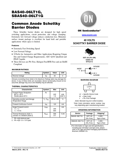
© Semiconductor Components Industries, LLC, 1997 March, 2018 − Rev. 101Publication Order Number:BAS40−06LT1/DBAS40-06LT1G,SBAS40-06LT1GCommon Anode Schottky Barrier DiodesThese Schottky barrier diodes are designed for high speed switching applications, circuit protection, and voltage clamping. Extremely low forward voltage reduces conduction loss. Miniature surface mount package is excellent for hand held and portable applications where space is limited.Features•Extremely Fast Switching Speed•Low Forward Voltage•S Prefix for Automotive and Other Applications Requiring Unique Site and Control Change Requirements; AEC−Q101 Qualified and PPAP Capable•These Devices are Pb−Free, Halogen Free/BFR Free and are RoHS CompliantMAXIMUM RATINGSRating Symbol Value Unit Reverse Voltage V R40V Stresses exceeding those listed in the Maximum Ratings table may damage the device. If any of these limits are exceeded, device functionality should not be assumed, damage may occur and reliability may be affected.THERMAL CHARACTERISTICSCharacteristic Symbol Max UnitForward Power Dissipation @ T A = 25°CDerate above 25°C P F2251.8mWmW/°COperating Junction and StorageT emperature RangeT J, T stg−55 to +150°C Forward Continuous Current I FM120mASingle Forward Current t v 1 st v 10 ms I FSM200600mAThermal Resistance (Note 1) Junction−to−Ambient (Note 2)R q JA508311°C/W1.FR−4 @ minimum pad.2.FR−*******.0inpad.40 VOLTS SCHOTTKY BARRIER DIODE Device Package Shipping†ORDERING INFORMATION312SOT−23 (TO−236)CASE 318STYLE 12MARKING DIAGRAML2 M GGL2= Specific Device CodeM= Date Code*G= Pb−Free Package†For information on tape and reel specifications, including part orientation and tape sizes, please refer to our T ape and Reel Packaging Specifications Brochure, BRD8011/D.BAS40−06LT1G SOT−23(Pb−Free)3,000 /T ape & Reel (Note: Microdot may be in either location)*Date Code orientation and/or overbar mayvary depending upon manufacturing location.SBAS40−06LT1G SOT−23(Pb−Free)3,000 /T ape & ReelBAS40−06LT1G, SBAS40−06LT1G2ELECTRICAL CHARACTERISTICS (T A = 25°C unless otherwise noted)CharacteristicSymbol Min Max Unit Reverse Breakdown Voltage (I R = 10 m A)V (BR)R 40−VT otal Capacitance(V R = 1.0 V, f = 1.0 MHz)C T − 5.0pFReverse Leakage (V R = 25 V)I R − 1.0m Adc Forward Voltage (I F = 1.0 mAdc)V F −380mVdc Forward Voltage (I F = 10 mAdc)V F −500mVdcForward Voltage (I F = 40 mAdc)V F−1.0VdcProduct parametric performance is indicated in the Electrical Characteristics for the listed test conditions, unless otherwise noted. Product performance may not be indicated by the Electrical Characteristics if operated under different conditions.TYPICAL CHARACTERISTICS100V F , FORWARD VOLTAGE (VOLTS)101.00.110V R , REVERSE VOLTAGE (VOLTS)1.00.10.010.0013.50V R , REVERSE VOLTAGE (VOLTS)3.01.00.50C T , C A P A C I T A N C E (p F )5.0101540I F , F O R W A R D C U R R E N T (m A )Figure 1. Typical Forward VoltageFigure 2. Reverse Current versus ReverseVoltageFigure 3. Typical CapacitanceI R , R E V E R S E C U R R E N T (μA )10025201.52.02.53035SOT−23 (TO−236)CASE 318−08ISSUE ASDATE 30 JAN 2018SCALE 4:11XXXM G G XXX = Specific Device Code M = Date Code G = Pb−Free Package*This information is generic. Please refer to device data sheet for actual part marking.Pb−Free indicator, “G” or microdot “ G ”,may or may not be present.GENERICMARKING DIAGRAM*NOTES:1.DIMENSIONING AND TOLERANCING PER ASME Y14.5M, 1994.2.CONTROLLING DIMENSION: MILLIMETERS.3.MAXIMUM LEAD THICKNESS INCLUDES LEAD FINISH.MINIMUM LEAD THICKNESS IS THE MINIMUM THICKNESS OF THE BASE MATERIAL.4.DIMENSIONS D AND E DO NOT INCLUDE MOLD FLASH,PROTRUSIONS, OR GATE BURRS.SOLDERING FOOTPRINTDIM A MIN NOM MAX MINMILLIMETERS0.89 1.00 1.110.035INCHES A10.010.060.100.000b 0.370.440.500.015c 0.080.140.200.003D 2.80 2.90 3.040.110E 1.20 1.30 1.400.047e 1.78 1.90 2.040.070L 0.300.430.550.0120.0390.0440.0020.0040.0170.0200.0060.0080.1140.1200.0510.0550.0750.0800.0170.022NOM MAX L1STYLE 22:PIN 1.RETURN2.OUTPUT3.INPUT STYLE 6:PIN 1.BASE2.EMITTER3.COLLECTOR STYLE 7:PIN 1.EMITTER2.BASE3.COLLECTOR STYLE 8:PIN 1.ANODE2.NO CONNECTION3.CATHODESTYLE 9:PIN 1.ANODE2.ANODE3.CATHODESTYLE 10:PIN 1.DRAIN2.SOURCE3.GATE STYLE 11:PIN 1.ANODE 2.CATHODE 3.CATHODE−ANODE STYLE 12:PIN 1.CATHODE2.CATHODE3.ANODE STYLE 13:PIN 1.SOURCE2.DRAIN3.GATESTYLE 14:PIN 1.CATHODE2.GATE3.ANODESTYLE 15:PIN 1.GATE2.CATHODE3.ANODE STYLE 16:PIN 1.ANODE2.CATHODE3.CATHODE STYLE 17:PIN 1.NO CONNECTION2.ANODE3.CATHODE STYLE 18:PIN 1.NO CONNECTION 2.CATHODE 3.ANODE STYLE 19:PIN 1.CATHODE 2.ANODE 3.CATHODE−ANODE STYLE 23:PIN 1.ANODE2.ANODE3.CATHODESTYLE 20:PIN 1.CATHODE2.ANODE3.GATE STYLE 21:PIN 1.GATE2.SOURCE3.DRAIN STYLE 1 THRU 5:CANCELLEDSTYLE 24:PIN 1.GATE2.DRAIN3.SOURCESTYLE 25:PIN 1.ANODE2.CATHODE3.GATESTYLE 26:PIN 1.CATHODE2.ANODE3.NO CONNECTIONSTYLE 27:PIN 1.CATHODE2.CATHODE3.CATHODE2.10 2.40 2.640.0830.0940.104H E 0.350.540.690.0140.0210.027c0−−−100−−−10T°°°°(Note: Microdot may be in either location)TOP VIEWEND VIEWDIMENSIONS: MILLIMETERS3X3XRECOMMENDED STYLE 28:PIN 1.ANODE2.ANODE3.ANODEMECHANICAL CASE OUTLINEPACKAGE DIMENSIONS© Semiconductor Components Industries, LLC, 2018 January, 2018 − Rev. AS Case Outline Number:318ON Semiconductor and are registered trademarks of Semiconductor Components Industries, LLC (SCILLC). SCILLC reserves the right to make changes without further notice to any products herein. SCILLC makes no warranty, representation or guarantee regarding the suitability of its products for any particular purpose, nor does SCILLC assume any liability arising out of the application or use of any product or circuit, and specifically disclaims any and all liability, including without limitation special, consequential or incidental damages.“Typical” parameters which may be provided in SCILLC data sheets and/or specifications can and do vary in different applications and actual performance may vary over time. All operating parameters, including “Typicals” must be validated for each customer application by customer’s technical experts. SCILLC does not convey any license under its patent rights nor the rights of others. SCILLC products are not designed, intended, or authorized for use as components in systems intended for surgical implant into the body, or other applications intended to support or sustain life, or for any other application in which the failure of the SCILLC product could create a situation where personal injury or death may occur. Should Buyer purchase or use SCILLC products for any such unintended or unauthorized application, Buyer shall indemnify and hold SCILLC and its officers, employees, subsidiaries, affiliates, and distributors harmless against all claims, costs, damages, and expenses, and reasonable attorney fees arising out of, directly or indirectly, any claim of personal injury or death associated with such unintended or unauthorized use, even if such claim alleges that SCILLC was negligent regarding the design or manufacture of the part. SCILLC is an Equal Opportunity/Affirmative Action Employer. This literature is subject to all applicable copyright laws and is not for resale in any manner.ON Semiconductor and are trademarks of Semiconductor Components Industries, LLC dba ON Semiconductor or its subsidiaries in the United States and/or other countries.ON Semiconductor owns the rights to a number of patents, trademarks, copyrights, trade secrets, and other intellectual property. A listing of ON Semiconductor’s product/patent PUBLICATION ORDERING INFORMATION。
ANTECH膜壳(北京安泰久盛环保科技)
ANTECH 膜壳
————————
行业领先品牌
——————
膜壳组件
名称:8” 密封板、承压板组合件 材质:尼龙、铝合金 编号:AT-8001
名称:端板 材质:4” 密封板 编号:AT-4001
名称:月牙形挡板、螺栓 材质:锌合金 编号:AT-8002
名称:挡片、螺栓 材质:不锈钢 编号:AT-8003
L
mm 1470 2486 3502 INCH 27.56 57.24 81.26
S
mm 700 1454 2064 INCH 44.88 84.88 124.88
P
mm 1140 2156 3172
D(外径)
INCH 8.43 8.43 8.43 mm 214 214 214
4” 系列:
ANTECH 膜壳 ———————— 行业领先品牌
名称:拷贝林 材质:不锈钢 编号:AT8009
名称:密封圈 材质:优质硅胶 编号:AT-8010
名称:卡箍 材质:不锈钢 编号:AT-8011
ANTECH 膜壳
————————
行业领先品牌
11
——————
安装说明
进行安装操作之前,请熟识膜壳各配件功能参数,由有操作经验的专业人 员进行规范正确的组装。不正确的组装作业会严重影响膜壳组件各项性能、使 膜组件磨损渗漏、端头爆裂失效并引发人身安全事故。对于不正确的安装操作 所产生的一切不良后果,本公司免责。
特点:
端联和侧联可选 玻璃钢(FRP)缠绕,经久耐用 外表聚酯涂层使膜壳不受环境腐蚀 月牙形挡板确保拆装简便、安全 ———————— 行业领先品牌
3
ANTECH 膜壳
——————
POREX 管式微滤膜组件说明书

为什么选择博滤克斯管式微滤膜组件?性能特点• 高通量• 长寿命• 可反洗• 多种过滤孔径• PVDF 或PE支撑层可选• 优异的化学耐受性和耐温性能• 多根膜管并联的组件结构•专利所有的支撑层与膜层连接结构(PVDF/PVDF)• 博滤克斯管式微滤膜可提供连续、稳定可靠的固液分离功能,并具有很长的使用寿命。
• PE 烧结支撑层与PVDF 的膜层结合形成高性能的管式膜,具有非常突出的操作特点。
• 专利所有的PVDF 支撑层与PVDF膜层结合,则赋予更高的耐温性能和更强化的化学耐受性 (pH 操作范围0-14)。
• 出色的化学耐受性和耐摩擦性。
• 多种膜孔径和两种支撑层可供选择。
• 独一无二的热熔接多向匀孔的 骨架结构为管式过滤膜提供了 更优化的支撑。
• 根据具体应用的通量和固含 量(最高可达重量比5%)的要求有多种排列方式可选。
• MM 形式的组件仅适用于S01, 002, 和005三种孔径规格的膜组件。
• 15芯、37芯和61芯膜组件内仅使用半英寸膜管。
备注有关具体的产品选型请与我们工厂咨询。
先进的材料技术每一支博滤克斯管式膜组件都包含多根膜管,这些定制结构的膜管是由PE 或PVDF原材料烧结而成,形成了内部错综复杂的、多向均匀开孔的网格形式骨架结构。
这些支撑层上的孔隙然后被膜层填充,从而独特地将良好的过滤性能和过滤强度这两者结合在一起。
更高的耐压性能• 通量增加• 系统占地减少• 反冲效率提高坚韧均一的复合膜材料• 即便膜表面的刮擦不会破坏结构上的完整性博滤克斯管式微滤膜(TMF™)组件具有独一无二的、专利所有的膜管结构。
膜层与支撑层紧密结合形成超高强度的一体式复合结构,允许更高的操作压力和反洗压力,从而使得通量更高,占地更少。
这种一体式管式膜组件是由PVDF 膜层固定在PVDF 或PE 的支撑骨架上形成的锚形镶嵌结构。
性能优异的设计结构膜材料化学耐受性博滤克斯的多孔塑料是由热塑性材料制成,因而对于腐蚀性化学物质和溶剂具有广谱耐受性。
吉林海普科技发展有限公司膜分离技术与设备说明书
Hydropure海普科技液体物料的分离、浓缩、纯化、澄清Separating、Concentrating、Purification、clarification For The Liquids反渗透(RO)、纳滤(NF)、超滤(UF)、微滤(MF)服务于:汽车、医药、化工、生物、食品、饮料、能源、环保、饮水等领域。
吉林海普科技发展有限公司JILIN HYDROPURE SCI&TECH DEVELOPMENT CO.,LTD膜分离技术与设备膜分离技术简介利用具有选择性分离功能的半透膜实现液体物料(或气体)的不同组分间的分离、纯化、浓缩、澄清的过程称作膜分离过程。
它与传统过滤的不同在于,膜可以在分子、离子范围内进行分离,并且这个过程是一种物理过程,不需发生相的变化。
根据其孔径或截留分子量的不同,可将膜分为微滤膜、超滤膜、纳滤膜和反渗透膜,根据材料的不同,可分为无机膜和有机膜,无机膜主要还只有微滤级别的膜,主要是陶瓷膜和金属膜。
有机膜是由高分子材料制成的,如聚偏氟乙烯、芳香族聚酰胺、聚醚砜、聚氟聚合物等,是目前应用最为广泛的膜材料,其主要优点是填装密度大,使用操作简便,行业标准比较一致。
膜分离方法优点(1)膜分离过程不发生相变化,和其它方法相比能耗较低,因此膜分离技术是一种节能技术;(2)膜分离过程是在压力(或电力)驱动下,常温下进行,因而特别适用于对热敏性的物质,如对果汁、酶等的分离与浓缩过程,在食品工业、医药工业、生物技术等领域具有独特的适应性;(3)膜分离技术不仅适用于有机物和无机物的分离,从病毒、细菌到微粒的广泛分离,而且还适用于许多特殊溶液体系的分离,如溶液中大分子与无机盐的分离,一些共沸物或近沸点物质的分离等;(4)膜分离装置简单,操作容易且易控制,便于维修又分离效率高,作为一种新型的水处理方法与常规水处理方法相比,具有占地面积小、处理效率高、可靠性高等优点。
海普科技我公司是一家以科技人员为主体的高科技股份制企业,做为致力于液体物料分离和过滤技术二十余年的专业公司,我们与世界知名的分离、过滤产品生产商以及国内科研单位密切合作,努力将世界上最先进的液体物料分离和过滤技术及产品推广、并应用到各相关领域,推动其技术与生产的发展。
水平多关节型机器人 LS20-B系列 机器人手册说明书
机器人手册LS20-B 系列 Rev.4水平多关节型机器人LS20-B系列机器人手册Rev.4Copyright 2019-2020 SEIKO EPSON CORPORATION. All rights reserved.iLS20-B Rev.4前言感谢您购买本公司的机器人系统。
本手册记载了正确使用机器人所需的事项。
安装该机器人系统前,请仔细阅读本手册与其他相关手册。
阅读之后,请妥善保管,以便随时取阅。
保修本机及其选装部件是经过本公司严格的质量控制、测试和检查,并在确认性能满足本公司标准之后出厂交付的。
在交付产品的保修期内,本公司仅对正常使用时发生的故障进行免费修理。
(有关保修期事项,请咨询您的区域销售办事处。
)但在以下情况下,将对客户收取修理费用(即使在保修期内):1. 因不同于手册内容的错误使用以及使用不当而导致的损坏或故障。
2. 客户未经授权进行拆卸导致的故障。
3. 因调整不当或未经授权进行修理而导致的损坏。
4. 因地震、洪水等自然灾害导致的损坏。
警告, 小心, 使用:1. 如果机器人或相关设备的使用超出本手册所述的使用条件及产品规格,将导致保修无效。
2. 本公司对因未遵守本手册记载的“警告”与“注意”而导致的任何故障或事故,甚至是人身伤害或死亡,均不承担任何责任,敬请谅解。
3. 本公司不可能预见所有可能的危险与后果。
因此,本手册不能警告用户所有可能的危险。
ii LS20-B Rev.4商标Microsoft、Windows及Windows标识为美国Microsoft Corporation在美国及其它国家的注册商标或商标。
其它品牌与产品名称均为各公司的注册商标或商标。
注意事项禁止擅自复印或转载本手册的部分或全部内容。
本手册记载的内容将来可能会随时变更,恕不事先通告。
如您发现本手册的内容有误或需要改进之处,请不吝斧正。
制造商联系方式有关咨询处的详细内容,请参阅下记手册序言中的“销售商”。
不锈钢8040膜壳尺寸
不锈钢8040膜壳尺寸1.引言1.1 概述概述:不锈钢8040膜壳是一种常用于水处理和污水处理领域的设备,它被广泛应用于逆渗透等膜分离技术过程中。
膜壳的尺寸是影响其性能和应用范围的重要因素之一,因此了解不锈钢8040膜壳的尺寸特点对于选择合适的膜壳以及实施膜分离工艺至关重要。
不锈钢8040膜壳的尺寸通常通过其直径、长度和连接口尺寸来描述。
一般来说,膜壳的直径越大,处理水量也就越大,适用于大型的水处理系统。
而长度则决定了膜壳中可以安装多少个膜元件,进而决定了设备的处理能力。
此外,膜壳的连接口尺寸也是需要考虑的因素之一。
连接口的尺寸会影响设备的操作和维护,以及与其他设备之间的匹配性。
因此,在选购不锈钢8040膜壳时,需要确保其连接口尺寸能够与其他设备或管道进行有效连接。
总的来说,不锈钢8040膜壳的尺寸是影响其应用性能和适用范围的重要因素。
在选择合适的膜壳时,需要考虑膜壳的直径、长度和连接口尺寸,以确保其能够满足特定的处理需求,并与其他设备有效匹配。
对于水处理和污水处理领域的工程师和操作人员来说,了解不锈钢8040膜壳的尺寸特点将有助于他们做出明智的选择并优化工艺设计。
1.2文章结构在文章结构部分,我们将介绍本文的整体构架和组织方式。
本文旨在探讨不锈钢8040膜壳尺寸的相关要点,并对其进行详细说明和分析。
首先,在引言部分,我们将对本文的背景和意义进行概述。
通过介绍不锈钢8040膜壳的重要性和应用领域,读者可以更好地了解为何该主题具有研究和探索的价值。
接下来,我们将明确文章的目的。
通过指明我们的研究目标和意图,读者可以更清晰地了解我们的研究方向和解决问题的方法。
在正文部分,我们将重点介绍不锈钢8040膜壳尺寸的关键要点。
通过深入分析不同尺寸对膜壳性能的影响,我们将提供详细的尺寸参数和相关指导,帮助读者在实际应用中选择合适的膜壳尺寸。
具体而言,我们将在要点1中讨论不锈钢8040膜壳尺寸的基本概念和分类。
8040玻璃钢膜壳简要说明及进水方式
8040玻璃钢膜壳简要说明及进水方式根据膜壳的材料分为国内外反渗透膜壳及玻璃钢膜壳两种。
从目的分为家用反渗透膜壳、商业玻璃钢膜壳两种。
从函数可分为低压膜壳、海水淡化玻璃钢膜壳。
是反渗透系统核心部件之一,用于支持和固定的反渗透膜。
质量也会影响反渗透系统的操作,一连串的反渗透系统运作破坏反渗透膜,膜的恶化最终导致成品水泄漏,系统泄漏高压膜壳逐渐发生变形,焊接,造成不必要的麻烦和成本给客户。
从进水方式上一般可以分为端进端出型、普通侧进侧出型、端面特殊处理侧进侧出型三种。
玻璃钢膜壳简要说明:全部采用不锈钢制成,膜壳内外抛光,进水方式:两端进水(A型)、两侧进水(B型),结构:标准的零配件,拆卸方便快捷密封性:经耐压测试,两端组织结构:卡箍式-玻璃钢膜壳,法兰式-玻璃钢膜壳,内置式-玻璃钢膜壳玻璃钢膜壳详细说明:1、全部采用不锈钢制成,膜壳内外抛光2、进水方式:两端进水(A型)、两侧进水(B型)3、结构:标准的零配件,拆卸方便快捷4、密封性:经耐压测试5、两端组织结构:卡箍式,法兰式,内置式不锈钢反渗透膜壳简要说明:◆ FRP缠绕外壳,经久耐用。
◆ 进水口螺纹连接可选项:1/2″、3/4″内螺纹。
◆ 淡水出水口螺纹连接:1/2″内螺纹。
◆ SS316L半月形锁板易于操作,安全可靠。
8″不锈钢反渗透膜壳简要说明◆ FRP缠绕外壳,经久耐用。
◆ 侧开口及端开口可选。
◆ 减少30%的头部组件。
◆ 整体式锁紧推力环,在高速水流的状态下减少压降。
其锥形设计保证极高的耐压性能,最高可达275kgf/cm2。
◆ SS316L挤压成型三圈式挡圈和预埋嵌入环确保头部组件装配简便、安全。
◆ 外表面聚胺酯涂层,保护膜壳不受环境损害,并确保外观的美观大方。
◆ 标准色为白色,并提供其他可选色。
上面的例子表明,玻璃钢膜壳技术创新在当今世界主要从事膜的性能的提高和改善。
研究和开发的膜和膜壳制造业在中国的科技创新能力已经成为世界水处理技术发展的前沿。