磁性浮子液位计安装说明书
磁浮子液位计
浮标液位计使用说明书一、产品概述浮标液位计是我公司研制的一种简易的液位测量仪表,它广泛应用于石油、化工、电力、冶金、医药、供水等领域中的用于储存腐蚀性液体的槽、罐等平底拱顶容器与供水系统水塔的液位(界面)测量,解决了贮罐的液位测量和用人工上罐顶用钢尺测量困难等问题,并能获得准确有测量结果,被测介质可为酸性、碱性或高粘度。
该仪表具有外形结构简单、测量精度高、液位显示直观、清晰,无盲区,可远距离观测等优点,是液位测量的理想仪表。
二、结构原理该产品是以浮标为测量元件,浮标随液位的变化沿导向钢丝绳上、下浮动,通过牵引浮标的钢丝绳带动容器外另一端的重锤和指针同步反向移动,指针连续指示出液位的高度。
根据力平衡原理,假设当液位处于某一高度时浮标重量为W,重锤指针重量为W1,浮标浸在液体中所受到的浮力为F,系统摩擦力为f。
在平衡状态下:W-F-W1-f=0。
当液位上升时,浮力F增大,W、W1和f均不变,上式平衡破坏,重锤指针下滑。
直到F力减小到原来值,新的平衡才建立。
如F力一直在增大,即液位一直在上升,则重锤指针一直下滑。
反之,液位下降,则重锤指针上升。
以此来指示液位的高度。
如果选用法兰连接式并带磁偶合指示器的浮标液位计,不但具有液红汽蓝的双色显示功能,同时还可配液位变送器来连续输出4~20mA直流信号,实现远距离控制。
三、产品特点◆外形结构简单美观、牢固,安装、操作方便。
◆读数直观、醒目,可远距离观测。
◆测量范围大、无盲区。
◆可以测量腐蚀性强、高粘度的介质。
四、产品分类及使用范围1、该产品按使用功能可分为普通型和封阻型两种类型,其使用范围如下:(1)普通型主要适用于无腐蚀性或毒性气体溢出的场合;(2)封阻型主要适用于有腐蚀性或毒性气体溢出的场合。
2、该产品按连接形式可分为法兰连接型和螺纹连接型两种类型,其使用范围如下:(1)法兰连接型主要适用于被测介质为有腐蚀性或毒性的液体的场合;(2)螺纹连接型主要适用于常压、无腐蚀性或毒性气体溢出的场合。
浮球液位计安装和使用说明注意事项范本

工作行为规范系列浮球液位计安装和使用说明注意事项(标准、完整、实用、可修改)编号:FS-QG-88984浮球液位计安装和使用说明注意事项Float level gauge installation and use instructions说明:为规范化、制度化和统一化作业行为,使人员管理工作有章可循,提高工作效率和责任感、归属感,特此编写。
浮球液位计的组成浮球液位计由浮球、插杆等组成。
浮球液位计通过连接法兰按装于容器顶上,浮球根据排开液体体积相等等原理浮于液面,当容器的液位变化时浮球也随着上下移动,由于磁性作用,浮球液位计的干簧受磁性吸合,把液面位置变化成电信号,通过显示仪表用数字显示液体的实际位置,浮球液位计从而达到液面的远距离检测和控制。
浮球液位计的注意事项浮球液位计应安装在其浮球上下运动时不受妨碍的位置上。
1.被测介质不应含有铁磁性杂质。
2.为了防止运输基本型MYFQ-JB磁性浮子液位计仪表的浮球在密封管上高速滑落或撞击,引起测量带脱出,故仪表在出厂前,用卡箍将浮球固定在密封密管底部,磁钢在密封管顶部。
用户在安装.3.使用前应先拆去卡箍,将浮球上升至密封管顶部,然后轻缓地将浮球下移,针针应作相应的转动。
4.浮球液位计的面扳指示为指针式,满度测量时指示数字为喱针方向排列,空度测量时指示数字为逆时针方向排列。
5.浮球液位计出厂时附有安装法兰,用户应有配管道法兰浮球液位计的2种浮动形式浮球液位计有两种浮动形式,一种是浮球动,导杆不动;另一种则是浮球和导杆同时动。
前一种浮球和导杆间不能有杂物,这一点选型时就要注意。
后一种要避免导杆溅上杂物,同时这种形式抗介质流动的能力较小,安装定位时要注意避免。
共同的基本要求是浮球上下运动时不能有阻碍。
安装垂直度要符合要求,在介质存在流动时要避开急流安装,必要时可加强导杆固定或加装静止套。
请输入您公司的名字Foonshion Design Co., Ltd。
UHZ磁浮子液位计安装说明书
2.液位上升时,以红色显示液位高度;红色上部为白色,显示无液部分。
根据HG/T21584-95化工部标准4.5条规定:
a).水压试验时,浮子,浮球按1.25倍公称压力单独进行,不参与工艺容器耐压强度试验:
b).主体管水压试验,按1.5倍公称压力进行,但须将浮子取出。
二、技术参数
1、测量范围:350~12000mm(也可根据用户要求定做)
2、测量精度:
≤±10mm
3、介质压力:
-1.0~10.0Mpa
4、介质温度:
≤400℃
5、介质粘度:
≤0.15pas
6、介质比重:
≥0.45g/cm3
7、管体材质:
由具体介质确定
8、安装xx:
标准DN
20、DN25(也可以根据用户要求)
9、排污阀:
(Q11f-″)内螺纹管式球阀
放气孔:
″管堵头
三、安装
a)用户在收到产品时应认真检查产品,是否在运输中受到的损害,并且检查是否和定货要求一致。检查完好后按照以下顺序准确安装.
b)浮子和测量管分开包装。移除底部法兰,保持浮子顶部向上,将浮子装入测量管内,将底部法兰安装好。然后与被测容器连接.
c)浮子中的磁性体与显示板上色条中的磁体作用,色标翻转,红色表示有液,白色表示无液.
注意:
浮子要轻拿轻放,以免损坏;在安装前必须将显示条用浮子全部调整为白色,以免影响读数。
四、运行
1、关闭底部排污阀
2、慢慢打开阀,随之浮子腔内的压力缓慢增大,如果压力迅速增大,有可能是浮子向上撞击而损害浮子。浮子将随液面移动,浮子和显示条通过磁耦合作用,旋转180度色标由白色变成红色,以此反映液位。
LevelSite 磁性浮球液位计说明书

Level1LevelSite ® Supplemental GuideFeaturesModel LSSMin Typical SystemFigure 12from the liquid; the tank remains sealed from the surrounding environment (See Figure 2). Accidental spills from sight-glass breakage are eliminated.LevelSite® consists of 3 major components: the float housing, a magnetic float, and the rotating flagassembly. The float housing is an engineered pressure vessel which is externally mounted to the tank. The float housing is designed to handle the same temperatures andpressures found in the tank. It is fabricated from a variety of materials, depending on the application. The alloy models are usually polyvinyliden fluoride (PVDF). Other materials are available on request.The float (See Figure 3), is equipped witha permanent ring magnet assembly. Thisassembly rides at the surface of the liquidcontained within the float housing, rising and falling as the liquid in the tank rises and falls.As the float moves up and down, a magnetic flux field maintains continuous contact with the rotating flags mounted on theoutside of the float housing. Flag rotation occurs as the fluxFigure 3Standard Alloy Float has a resolution of 1/2” (12.7 mm). Rotating flags have a square profilewith embedded permanent magnets. The flux field generated by the ring magnet in the float interacts with the flag magnets causing them to rotate as the float moves up and down inside the housing. After the flags rotate to the new position, the embedded magnets lock the flags in place, making the flags less sensitive to vibration (See Figures 4 and 5).LevelSite®’s rotating flags are mounted in a housingfabricated of extruded aluminum or polycarbonate. The assembly is attached to the outside of the float housing with stainless steel clamps. The ends are sealed against dust and moisture. Since the flags are never in contact with the liquid, they never need to be cleaned and they can’t discolor. If the rotating flag assembly is accidentally crushed, there is no danger of a liquid spill.The rotating flag assembly is available in aluminum orpolycarbonate and measures 1.18”(30 mm) and 1.02” (26 mm) wide,respectively (See Figure 6).Figure 5Figure 6Level3LevelSite ® Supplemental GuideGeneral SpecificationsAluminum flags are offered in an anodized finish of red andsilver or painted in red and white. Anodized flags are suitable for service up to 400°F (200°C); painted versions can be subjected to 600°F (316°C). A glass pane protects the flags. The housing is extruded, black anodized aluminum.Polycarbonate flag housings are clear and impact-resistant. They offer 180° visibility of the flags; level can be seen from front and sides (See Figure 5). Housing and flags can withstand temperatures to 250°F (121°C). Standard flag colors are red and white.LevelSite®s are designed according to the unique requirements of each application. Based on information provided by the user regarding operating temperature, pressure, and “normal” specific gravity of the liquid, a float is selected appropriate to the application. Maximum and minimum conditions are evaluated to ensure that the LevelSite® will function not only at the normal condition, but at each extreme. Maximum temperature and pressure are parameters used to design the pressure vessel (float housing).9 can be used as a guide in selecting the ANSI class flanges and materialsappropriate for your temperature and pressure conditions.Barksdale’s LevelSite® is a unique system that can be custom designed for many types of applications, from a stand-alone, no-power-required levelindicator to a fully-integrated electroniccomponent within a process controlsystem. It can be supplied with process connections located for any of the four standard patterns: top/bottom, top/side, side/side, or side/bottom (See Figure 7). For applications where tank-side mounting of the LevelSite is not practical or desired, top mounted versions are available. Liquid interface configurations require three process connections (See Figure 7).Quality and dependability are built into every BarksdaleLevelSite. As a registered ISO 9001 manufacturer, Barksdale meets the most demanding international standards. LevelSite® can be certified to ASME, ANSI, DIN, BSP and other codes.System SpecificationsFigure 7ConfigurationQualityMaterialPressure/temperature performance parameters for LevelSite housing constructed of 316 stainless steel are specified in the chart. Please consult the factory with pressures/temperatures requiring other alloys.MaterialPressure/temperature performance parameters for LevelSite housing constructed of PVC, PP or PVDF are specified in the chart. Please consult the factory with pressures/temperatures requiring other materials.Figure 8Alloy - maximum operating pressure vs.temperature for ANSI classification.Figure 9Engineered plastic - maximum operating pressure vs. temperatureSee Barksdale’s Standard Conditions of Sale • Specifications are subject to modification at any time • Bulletin #L0018-D • 02/08 • ©2008 • Printed in the U.S.A.43211 Fruitland Avenue • Los Angeles, CA 90058 • 800-835-1060 • Fax: 323-589-3463 • LevelSite ® Supplemental GuideOperating InstructionsGeneral InstallationLevelSite®s are measuring instruments and must be properly treated as such. Make sure that all parts are available and the connecting flanges on the tank correspond to those on theindicator. The float and limit switches (if applicable) are enclosed in a separate box. Remove the bottom connection flange (1) of the float chamber and insert the float with the top uppermost. Replace the bottom flange with the gasket, fixing it to the chamber by tightening all the bolts securely. The LevelSite® must be raised slowly and carefully so that the float is not damaged by severe impact.It is essential to ensure that the flanges on the tank are accurately aligned with the flanges on the LevelSite®. Non-alignment of the flanges causes distortion of the float chamber (2) with the possibility that the float (3) will stick. The Levelsite® must always be mounted vertically. Before commissioning, the flags in the flag assembly (4) must be aligned by means of a magnet so that they all show the color white (polycarbonate) or silver (aluminum). NOTE: It is essential for all flange bolts, the vent-plug (5) and the drain-plug (6) to be fully tightened.The electrical limit switches (7) may be attached at any point in the range on the indicator bar by means of a stainless steel clip. Ensure that the stainless steel clips are installed under the flag assembly. The maximum electrical switching capacity is specified on the nameplate of the limit switch (7) and must not be exceeded. IMPORTANT: The operation of the LevelSite® is based on the magnetic field principle. Ferrous strips, clamps, or screws must not be used.LevelSite®s are always application specific. The most important technical data such as pressure and temperature limits are specified accurately on the nameplate (8). However, the sales drawing for the model number referenced on the nameplate is specific and detailed to the application and is the governingspecification document. Before commissioning, a check must be made to ensure that the technical data shown on the nameplate corresponds exactly with the plant requirements. NOTE: Test pressure and test temperature of the plant must NOT exceed the specifications.The transmitter is installed on the side of the LevelSite® housing, utilizing stainless steel clips, with the transmitter’s probe along the housing. The transmitter may be used in addition to a visual indicator (rotating flag assembly) to provide electronic monitoring of fluid level. If the transmitter is used with a flag assembly, it may be necessary to slide the transmitter’s clamps under the flag assembly. The transmitter is supplied with a mark on its probe. This mark must line-up with the centerline of the processMechanical InstallationElectrical InstallationCommissioningconnector on the LevelSite®. If the transmitter’s probe spans the entire measuring range (center-to-center of the process connections), the probe will be marked to show the measuring range. Electrical Connections: Ground the transmitter’shousing if necessary. The cable length may be up to 3 miles. The transmitter is designed to be maintenance-free and is not field-serviceable. If the unit is not operating properly, replace the entire unit. For more information, refer back to “Tank Level Indicating Transmitter”.Tank Level Indicator (TLI) Installation。
磁翻板液位计的安装使用说明书

位计用在较高的压力容器上时,不得突然注入压
力,而过程中,由于液位突变或
其他原因造成个别翻板不能翻转,可
用校正磁钢N极或浮标进行校正。14.根据介质情
况,可定期清洗主导管,清除管内沉积物杂质。
1.红白磁柱安装时全部校对为白色2.红绿磁柱
安装时全部校对为红色0c67
标有箭头方向为上部,(或以有磁钢的一端为上
部)。液位计筒体内不应有固体杂质和磁杂质进
入,以免对浮子造成卡阻及减弱浮力。11.液位
计投入运行时,应先打开上引液管阀
门,然后慢慢开启下引液管阀门,让液体个质平
稳地直入主导管,避免液体介质带着浮子急速上
升,造成磁翻柱翻转失灵或翻乱(若遇此现象,
可用磁钢重新校正)。12.如果该液
f0e 密度计
4.液位计与容器之间应装有截止阀,以便清洗和
检修时切断物料。5.液位计筒体周围不容许有导
磁体靠近,否则会直接影响液位计正常工作。
6.液位计出厂时一般不保温,但可
根据用户需求代为保温。如用户自行采用伴热管
路时,必须选用非导磁材料。7.浮子一般放置在
液位计腔体一侧。为防止运输途中磁性浮子在主
导管内高速滑动而被撞击,液位计出
磁性浮子液位计是根据客户的要求特别订制的产
品,在使用和安装过程中需要注意的事项如下:
1.开箱检查仪表的型号是否与选购的型号一致,
法兰尺寸及中心距是否与现场尺寸一
一致。液位计上、下法兰的中心距为测量范围
2.仪表必须垂直安装,以保证磁性浮子在主导管
内上下运动自如,垂直度应小于3°3.安装前必
须清洁管道确保管道清洁无杂物堵塞
厂前,用卡丝将磁性浮子固定在下引液管处,用
户在安装使用前应先抽去卡丝方能安装。8.安装
磁翻板液位计说明书完整
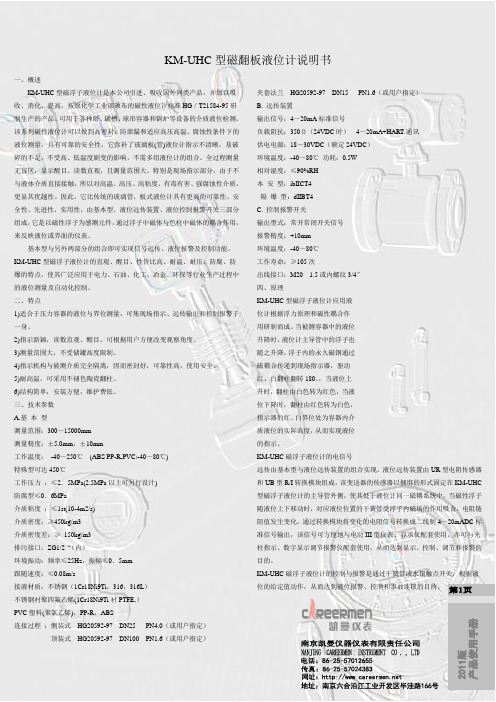
KM-UHC型磁翻板液位计说明书一、概述KM-UHC型磁浮子液位计是本公司引进、吸收国外同类产品,并加以吸收、消化、提高,按原化学工业部颁布的磁性液位计标准HG/T21584-95研制生产的产品。
可用于各种塔、罐槽、球形容器和锅炉等设备的介质液位检测。
该系列磁性液位计可以做到高密封,防泄漏和适应高压高温、腐蚀性条件下的液位测量,具有可靠的安全性,它弥补了玻璃板(管)液位计指示不清晰,易破碎的不足,不受高、低温度剧变的影响,不需多组液位计的组合。
全过程测量无盲区,显示醒目、读数直观,且测量范围大。
特别是现场指示部分,由于不与液体介质直接接触,所以对高温、高压、高粘度、有毒有害、强腐蚀性介质,更显其优越性。
因此,它比传统的玻璃管,板式液位计具有更高的可靠性、安全性、先进性、实用性。
由基本型、液位远传装置、液位控制报警开关三部分组成,它是以磁性浮子为感测元件,通过浮子中磁体与色柱中磁体的耦合作用,来反映液位或界面的仪表。
基本型与另外两部分的组合即可实现信号远传、液位报警及控制功能。
KM-UHC型磁浮子液位计的直观、醒目、性价比高、耐温、耐压、防腐、防爆的特点,使其广泛应用于电力、石油、化工、冶金、环保等行业生产过程中的液位测量及自动化控制。
二、特点1)适合于压力容器的液位与界位测量,可集现场指示、远传输出和控制报警于一身。
2)指示新颖,读数直观、醒目。
可根据用户方便改变观察角度。
3)测量范围大,不受储罐高度限制。
4)指示机构与被测介质完全隔离,因而密封好,可靠性高,使用安全。
5)耐高温,可采用不褪色陶瓷翻柱。
6)结构简单,安装方便,维护费低。
三、技术参数A.基本型测量范围:300~15000mm测量精度:±5.0mm,±10mm工作温度:-40~250℃(ABS PP-R,PVC:-40~80℃)特殊型可达450℃工作压力:≤2.5MPa(2.5MPa以上可另行设汁)防腐型≤0.6MPa介质粘度:≤1st(10-4m2/s)介质密度:≥450kg/m3介质密度差:≥150kg/m3排污接口:ZG1/2“(内)环境振动:频率≤25Hz,振幅≤0.5mm跟随速度:≤0.08m/s接液材质:不锈钢(1Cr18Ni9Ti,316,316L)不锈钢衬聚四氟乙烯(1Cr18Ni9Ti衬PTFE,)PVC塑料(聚氯乙烯),PP-R,ABS连接过程:侧装式HG20592-97 DN25 PN4.0(或用户指定)顶装式HG20592-97 DN100 PN1.6(或用户指定)夹套法兰HG20592-97 DN15 PN1.6(或用户指定)B. 远传装置输出信号:4~20mA标准信号负载阻抗:350Ω(24VDC时)4~20mA+HART通讯供电电源:18~30VDC(额定24VDC)环境温度:-40~80℃功耗:0.5W相对湿度:≤90%RH本安型:ibIICT4隔爆型:dIIBT4C. 控制报警开关输出型式:常开常闭开关信号报警精度:+10mm环境温度:-40~80℃工作寿命:≥105次出线接口:M20 1.5或内螺纹3/4″四、原理KM-UHC型磁浮子液位计应用液位计根据浮力原理和磁性耦合作用研制而成。
UHZ磁浮子液位计安装说明书
U H Z系列船用磁浮子液位计安装使用说明书ISO9001:2000认证合格单位辽阳市顺达仪表厂一、工作原理及用途磁浮子式液位计是以磁性浮子为感应元件,并通过磁性浮子与显示色条中磁性体的耦合作用,反映被测液位或界面的测量仪表。
磁浮子式液位计和被测容器形成连通器,保证被测量容器与测量管体间的液位相等。
当液位计测量管中的浮子随被测液位变化时,浮子中的磁性体与显示条上显示色标中的磁性体作用,使其翻转,红色表示有液,白色表示无液,以达到就地准确显示液位的目的。
就地显示磁性浮子式液位计具有显示直观醒目、不需电源,安装方便可靠,维护量小,维修费用低的优点,是玻璃管,玻璃板液位计的升级换代产品。
可广泛应用于石油,化工,电站,制药,冶金,船舶工业,水/污水处理等行业的罐,槽,箱等容器的液位检测。
用户还可根据工程需要,配合磁控液位计使用,可就地数字显示,或输出4~20mA的标准远传电信号,以配合记录仪表,或工业过程控制的需要。
也可以配合磁性控制开关或接近开关使用,对液位监控报警或对进液出液设备进行控制。
二、技术参数1、测量范围:350~12000mm(也可根据用户要求定做)2、测量精度:≤±10mm3、介质压力:-1.0~10.0Mpa4、介质温度:≤400℃5、介质粘度:≤0.15pas6、介质比重:≥0.45g/cm37、管体材质:由具体介质确定8、安装法兰:标准DN20、DN25(也可以根据用户要求)9、排污阀:(Q11f-15PC1/2″)内螺纹管式球阀放气孔:GZ1/2″管堵头三、安装a) 用户在收到产品时应认真检查产品,是否在运输中受到的损害,并且检查是否和定货要求一致。
检查完好后按照以下顺序准确安装.b) 浮子和测量管分开包装。
移除底部法兰,保持浮子顶部向上,将浮子装入测量管内,将底部法兰安装好。
然后与被测容器连接.c) 浮子中的磁性体与显示板上色条中的磁体作用,色标翻转,红色表示有液,白色表示无液.注意:浮子要轻拿轻放,以免损坏;在安装前必须将显示条用浮子全部调整为白色,以免影响读数。
浮球液位计说明书
浮球液位计说明书篇一:浮球液位计说明书USX型磁浮球液位计一、概述浮球液位计由浮球、插杆等组成。
浮球液位计通过连接法兰安装于容器顶上,浮球根据排开液体体积相等等原理浮于液面,当容器的液位变化时浮球也随着上下移动,由于磁性作用,浮球液位计的干簧受磁性吸合,把液面位置变化成电信号,通过显示仪表用数字显示液体的实际位置,浮球液位计从而达到液面的远距离检测和控制。
浮球液位计具有结构简单,调试方便,可靠性好,精度高等特点,浮球液位计可广泛适用于高温、高压、粘稠、脏污介质、沥青、含腊等油品以及易燃、易爆、腐蚀性等介质的液位(界位)的连续测量。
浮球液位计可用于石油、化工原料储存、工业流程、生化、医药、食品饮料、罐区管理和加油站地下库存等各种液罐的液位工业计量和控制。
浮球液位计也适用于大坝水位,水库水位监测与污水处理等等二、产品技术参数:测量范围:0~3500mm 供电电压:12~36V DC输出信号:两线制4~20mA.DC或叠加数字信号,由用户选择开方或线性输出;负载电阻:250Ω测量精度:±2.5%F.S 环境温度:-40~80℃工作温度:-20~120℃公称压力:≤2.5MPa法兰标准:A:JB/T82.1-94(平面法兰)DN100 PN1.6 球φ90 B:JB/T82.1-94(平面法兰)DN80 PN0.6 球φ7633介质密度:≥0.65g/cm 介质粘度:≤0.015Pa.s 接液材质:不锈钢304 防爆等级:EX iaⅡCT 5三、接线图四、选型型号示例:插入深度2200mm,测量范围0-20XXmm,地下型(内置传感器上装式),配现场数显仪表(一次表),配套XM型智能数显仪可提供对外控制(触点常开动闭),普通型产品。
标记为:USX2-2200/20XXPAKb五、浮球液位计校验与试验:a. 下限(即零点)调试:浮球处于最低位置时(即零点),调下限旋钮,使数显表显示4mA。
b.上限(即满度)调试:将浮球移至最高位置或设定位置时(即满度),调上限旋钮,使数显表显示输出20mA。
浮球液位计说明书
浮球液位计说明书篇一:浮球液位计说明书浮球液位计说明书USX型磁浮球液位计一、概述浮球液位计由浮球、插杆等组成。
浮球液位计通过连接法兰安装于容器顶上,浮球根据排开液体体积相等等原理浮于液面,当容器的液位变化时浮球也随着上下移动,由于磁性作用,浮球液位计的干簧受磁性吸合,把液面位置变化成电信号,通过显示仪表用数字显示液体的实际位置,浮球液位计从而达到液面的远距离检测和控制。
浮球液位计具有结构简单,调试方便,可靠性好,精度高等特点,浮球液位计可广泛适用于高温、高压、粘稠、脏污介质、沥青、含腊等油品以及易燃、易爆、腐蚀性等介质的液位(界位)的连续测量。
浮球液位计可用于石油、化工原料储存、工业流程、生化、医药、食品饮料、罐区管理和加油站地下库存等各种液罐的液位工业计量和控制。
浮球液位计也适用于大坝水位,水库水位监测与污水处理等等二、产品技术参数:测量范围:0~3500mm 供电电压:12~36V DC输出信号:两线制4~20mA.DC或叠加数字信号,由用户选择开方或线性输出;负载电阻:250Ω测量精度:±2.5%F.S 环境温度:-40~80℃工作温度:-20~120℃公称压力:≤2.5MPa法兰标准:A:JB/T82.1-94(平面法兰)DN100 PN1.6 球φ90 B:JB/T82.1-94(平面法兰)DN80 PN0.6 球φ7633介质密度:≥0.65g/cm(界面介质密度差≥0.1g/cm) 介质粘度:≤0.015Pa.s 接液材质:不锈钢304 防爆等级:EX iaⅡCT 5三、接线图四、选型型号示例:插入深度2200mm,测量范围0-XXmm,地下型(内置传感器上装式),配现场数显仪表(一次表),配套XM型智能数显仪可提供对外控制(触点常开动闭),普通型产品。
标记为:USX2-2200/XXPAKb五、浮球液位计校验与试验:a. 下限(即零点)调试:浮球处于最低位置时(即零点),调下限旋钮,使数显表显示4mA。
TS1007-C磁 浮 子 液 位 计doc - 广电电器网
5
电 话:4006604460 传 真:024-23782108
网 址:http: 地 址:沈阳浑南新区世纪路 37 号
沈阳蓝光自控系统工程有限公司 TS1007-C 磁浮子液位计使用说明书
八、使用说明
1、使用时将表头后盖旋拧开,将电源启停按钮按下,显示表头开始工作。 2、当电池电压小于 14V 时,表头将不能正常工作,此时将电源启停按钮按到停止工 作状态,再将电池取下,将备用电池换上,按下电源启停按钮,仪器将正常工作。
六、安装形式
图2
电 话:4006604460 传 真:024-23782108
网 址:http: 地 址:沈阳浑南新区世纪路 37 号
4
沈阳蓝光自控系统工程有限公司 TS1007-C 磁浮子液位计使用说明书
七、定货须知
图3 订货时,用户需提供以下技术指标: 1、测量范围,以此图为例,则测量范围中间部分; 2、测量精度, 常规精度为 10mm; 3、硬管外径,常规尺寸为Φ32mm,精度为 10mm,如精度提高尺寸随之改变; 4、上下限设定值,如用户选定我公司智能数显仪,需提供此参考值。 5、法兰尺寸。
四、工作原理
TS1007-C 磁浮子液位计是利用磁效应产生变化的电信号,此信号经转换电路处理, 输出一个标准的 4 ~ 20mA 的二线制电流信号。
电 话:4006604460 传 真:024-23782108
网 址:http: 地 址:沈阳浑南新区世纪路 37 号
2
沈阳蓝光自控系统工程有限公司 TS1007-C 磁浮子液位计使用说明书
图4
九、注意事项
1、请按本说明书合理使用; 2、请勿私自拆卸本产品任何部分(引线端除外) ; 3、请勿带电连接电源线和信号线; 4、本产品属精密仪器,切勿猛力撞击,以避免造成机械损伤; 5、如浮子从硬管中脱离或超出测量范围,则输出为无效值。
- 1、下载文档前请自行甄别文档内容的完整性,平台不提供额外的编辑、内容补充、找答案等附加服务。
- 2、"仅部分预览"的文档,不可在线预览部分如存在完整性等问题,可反馈申请退款(可完整预览的文档不适用该条件!)。
- 3、如文档侵犯您的权益,请联系客服反馈,我们会尽快为您处理(人工客服工作时间:9:00-18:30)。
的作用下自动密封,防止容器内液体外溢,并保
证操作人员安全。磁翻板液位计太长了怎么办对
超过一定长度的[,需增加中间加固法兰或耳攀作
固定支撑,以增加强度和克服自身重
量;磁翻板液位计的安装位置,应避开或远离物
料介质进出口处,避免物料流体局部区域的急速
变化,影响液位测量的准确性;当配有远传配套
仪表时需做到如下几条:远传配套仪表
运输过。液位计安装完毕后,需要用磁钢进行校
正对翻柱导引一次使零位以下显示红色,零位以上显示白色。液位计投入运行时应 Nhomakorabea打开下引液
管阀门让液体介质平稳进入主体管,避
免液体介质带着浮球组件急速上升,而造成翻柱
转失灵和乱翻。若发生此现象待液面平稳后可用
磁钢重新校正。磁翻板液位计的7个使用注意事项
1.对超过一定长度(普通型>
磁翻板液位计位计可直接用来观察各种容器内介
质的液位高度。它适用于石油、化工等工业领域
的液位指示,该液位计结构简单,观察直观、清
晰,不堵塞、不渗漏,安装方便,维修
修简单。玻璃板液位计上、下端安装法兰与容器
相连接构成连通器,透过玻璃板可直接观察到容
器内液位的实际高度。上下阀门装有安全钢珠,
当玻璃因意外损坏时,钢珠在容器内压
检修或调试完成后应及时盖上。磁翻板液位计主
体周围不容许有导磁体靠近否则直接影响液位计
工F确工作。因运输过程中为了不使浮球组件损坏,
故出厂前将浮球组件取出液位计主
体管外,待液位计安装完毕后,打开底部排污法
兰,再将浮球组件重新装入主体管内,注意浮球
组件重的一头朝上,不能倒装。如果在出厂时已
经将浮球组件安装在主体管内,为保证
;3米、防腐型>2米)的液位计,需增加中间加
固法兰或耳攀作固定支撑,以增加强度和克服自
身重量;2.磁翻板液位计的安装位置,应避开或远
离物料介质进出口处,避
免物料流体局部区0c67f0e 密度计
零位应与液位计零位指示处在同一水平线上;远
传配套仪表与显示仪表或工控机之间的连线最好
单独穿保护管敷设或用屏蔽二芯电缆敷设;应使
远传配套仪表紧贴液位计主导管,并用
不锈钢抱箍固定(禁用铁质);远传配套仪表上
感应面应面向和紧贴主导管;接线盒进线孔敷设
后,要求密封良好,以免雨水、潮气等侵入而使
远传配套仪表不能正常工作,接线盒在