大众汽车标准_TLD_803005V1.010523347794616537
大众标准TL精编中文版
大众汽车集团标准 TL 2442010年12月版分类号:50223关键字:锌,镍,钝化处理,密封,无Cr(VI),防腐蚀,表面保护锌/镍-合金涂覆层表面保护要求旧版本TL 244: 1987-10, 1992-05, 1993-11, 1995-12, 2002-05, 2004-12, 2006-08, 2007-02变更相对于 TL244: 2007-02 版本,作了如下更改:--补充了热处理后零件的抗拉强度≦ 1200Mpa 部分;--添加了 Ofl-r647 和 Ofl-r648 两种涂覆方法;--原表 2 中关于含铬的表面保护类型已删除;--添加了图 1 和图 2;--添加了 PV 1209,PV 1200 和 PV1210 三种测试依据;--镀层表面形态的要求有所增加;--镍的上限值有所改变;--原第 4 条关于镀层厚度的测量的内容加入到 3.9 部分;--原 3.11 部分的要求有所改变;--参考标准有更新;--标准重组。
1 范围本标准规定了抗拉强度为 Rm≦ 1000Mpa(按 VW 137 50 的特征字母 r)的铁材料和钢制件上的电解离析和无Cr( VI)后处理的锌/镍合金涂覆层的要求。
此外还定义了抗拉强度值大于 1000Mpa时的应用极限。
本标准定义了合金涂覆不适用于抗拉强度 Rm>1200Mpa 和表面硬度>370HV 的钢制件。
而且适用于抗拉强度值在 1000Mpa 和 1200Mpa之间的钢制件时,必须按 DIN EN ISO 4042 作热处理。
这些当作坚固防腐层(稳定等级为 6)的涂覆层,亦特别适用于除了腐蚀负荷增加和温度负荷增加至150°C(例如:发动机室和刹车系统)之外的部件以及螺栓拧紧系统。
银色涂覆层(例如:Ofl-r642,Ofl-r643,Ofl-r645和Ofl-r647)特别适用于导线连接(接地线连接)。
这些涂覆层特别适用于内部传动的紧固元件,以避免附加的施力作用。
VAS-PCODIS诊断系统大众奥迪车系所有通道号

VAS-PCODIS诊断系统大众奥迪车系所有通道号各位汽车技师朋友:您们好!汽车高级诊断技师培训中心微信公众号随时更新,如果你觉得资料不错,请转发一下到你的QQ空间与微信朋友圈让汽车维修一线技师共同关注,一起共享知识,一起为美好的生活每天注入新的能量!有人用微信......有人用微信学习成长!95%技师在这里学习进步!不落伍就关注!途安、途锐、辉腾;途锐轮胎气压灯基本设定大众新5053—65—16—1089610匹配——通道5输入左前胎压10匹配——通道6输入右前胎压10匹配——通道8输入右后胎压10匹配——通道7输入左后胎压发动机 01 -04 -060 节气门控制单元74--废气再循环组合阀 1.8T 77 --二次空气系统01-10-0 0 删除节气门控制单元自学习值17-11-11463 激活巡航功能带定速巡航功能的大众车17-11-16167 关闭巡航功能自动变速器02-0 4-000 强制低挡功能所有大众自动挡的车01-04-063ESP(ABS) 03-04-001 加液排气带ESP的03-04-010(POLO GP)60 方向盘转角传感器 G85 63 横向加速度传感器 G20066 制动压力传感器 G201 93 ESP激活103 ESP关闭 114-ESP设定固定登陆码空气悬挂系统 34-16-31564 空气悬挂自适应途锐.辉腾. 固定登陆码10 -1 左前轮高度自适应 497mm 2-右前轮高度自适应 497mm:3--左后轮高度自适应 502mm 4 -左后轮高度自适应 502mm胎压系统65-16-10896 轮胎监控自适应途锐.辉腾. 固定登陆码10 5--左前胎压自适应 2.4-2.8pa 10-6 右前胎压自适应 2.4-2.8pa10-7 左后胎压自适应 2.8-3.2pa 10-8 右后胎压自适应 2.8-3.2pa 组合仪表 17-11-13861 更换里程表输入里程用固定登陆码10-2 保养周期显示复位用于消除保养提示输入0即可10-3 燃油消耗显示校正 10-4 仪表信息系统语言选择10-9 里程显示自适应总里程数小于100公里的表预输入的数字大于10010-16 读出里程脉冲数10-30 燃油表自适应燃油表指针随动示值120-136之间变化10-40 输入保养周期内剩余里程10-43 保养间隔里程输入仪表编码后数第二位1车型舒适系统 46-10-0 清除所有的遥控钥匙开=1;关=0: `10-1 匹配所有的遥控钥匙10-3 自动锁上/打开车速达每小时15公里,自动上锁10-4 自动锁上/打开点火钥匙拔出,车门自动开锁10-5 解除内部监控10-6 开锁喇叭响开锁确认信号10-7 锁车喇叭响锁车确认信号10-8 锁车转向信号闪转向信号闪2次,确认锁已开10-9 开锁转向信号闪转向信号闪1次,确认锁车10-10 设置警报喇叭警报方式带遥控警报器的大众车2=德国;3=英国;1=其他国家10-24 后尾箱自适应 phaeton 开=1;关=08 k1 i开=1;关=08 安全气囊 15-10-1 ?关闭副驾驶员气囊 :10-2 ?关闭驾驶员气囊 ! 10-3 关闭右侧气囊10-4 关闭左侧气囊自动空调 08- 4 -0 空调器翻版电机带自动空调的车型 )左大灯 29-4-1 左大灯自适应 phaeton.touareg 83右大灯 39-4-1 右大灯自适应 phaeton.touareg 83天窗系统 38-8-33 内部监测是否打开 phaeton.touareg防盗系统 175和17-8 -81 读取车架号和防盗码 phaeton.touareg11(16)PIN 密码10-21 钥匙数量最多8把.点压不能低与12.7V11-19795 更换kessy 17-7 编码8 23 更新原PIN途锐大灯编码;09---07 --105724(0105697)辉腾车后备箱开关设定46-12-24-0--ACCEPT---保存途安、途锐、辉腾 Can-Bus 的区别:途安:1T,VW Touran, 01,02,03,08,09,15,16,17,18,19,25,37,3D,42,44,46,52,55,56,62,69,7 2,76,77,7D途锐:7L,VW Touareg,01,02,03,05,06,08,09,11,15,16,17,18,19,1C,22,29,34,36,3 7,39,46,47,56,65,68,69,6E,75,77辉腾:3D,VW Phaeton D1,01,02,03,05,06,07,08,09,11,13,15,16,17,18,19,23,27,28,29,34,3 6,37,38,39,46,47,57,65,66,68,69,71,75,76,77其中:01,发动机 02,自动变速箱 03,ABS05,启动授权模块 06,乘客坐椅 07,大灯控制!08,自动空调; 09,中央电器系统 0D,左侧滑门11,发动机 I2电子离合器 13 距离控制14,电控悬架 15,安全气囊 16,方向盘电器.17,仪表 18,辅助加热 19,CAN网关1C,位置监测 21,发动机III 22,四轮驱动23,刹车调压 24,驱动防滑 25,电子防盗26,电动天窗 27,后灯光控制 28,后空调29,左侧灯光 31,发动机其他 32,差速锁止机构34,车身调平 35,中央门锁* 36,司机座椅控制37,巡航控制 38,天窗控制 39,右侧灯光41,柴油泵 42,司机侧门 43,刹车辅助44,转向辅助 45,内部监控 46,舒适系统47,音响系统 48,左后座椅控制 49,自动大灯51,电子驱动 52,乘客侧车门 53,驻车制动! 54,后扰流板 55,氙灯射程 56,收音机57,电视 58,辅助燃油箱 59,牵引保护61,电瓶控制 62左后车门 63,司机辅助系统64,稳定系统 65,轮胎气压 66,右后座椅控制67,语音控制 68,雨刮器 69,拖车控制71,电瓶充电 72,右后车门 73,乘客辅助系统75,紧急呼叫 76,停车辅助 77,车载电话78,滑门 7D,辅助加热奥迪系列;蓝牙匹配77-12-133-0激活 77-12-134-1激活免提A4B6拖车控制单元匹配J345-12-64ABS,ESP测试激活03-04-03激活 03-04-103关闭油浮子匹配17-12-30-128(最底线)-134(八升位置)仪表语言转换17-12-04-002(英语)-008(中文)G85,03-11-40168,03-08-05,03-04-01转向角度正负0点25内A4部件保护{空调08-12-81-26467转向柱电器J52716-12-81-00111车载供电控制单元J519,09-12-81-46992座椅记忆控制单元36-12-81-20771关闭、接通A6副驾驶安全气囊15-12-01-00001(关闭)-00000(打开)关闭、打开巡航01-11-11463(打开)-16167(关闭)A4运输保护模式17(56)-12-99-00000(关闭)-00001(开启)A6里程数17-11-13861 10-09-里程数除以10的数值A8D3运输模式(电瓶管理运输模式61-12-01-00000(关闭)-00001(开启)气动悬架运输模式34-12-10273(开启)-41172(关闭)转向角转感器校零03-11-40168 03-04-01-左右打方向大于15度--确定保养灯归零17-12-02-0-保存17-12-42-最小里程17-12-43-最大里程 17-12-44-保养天数节气门,强制降档基本设定01-04-60 01-04-63-油门踏到底-保存电子后刹车片更换设定 53-06-007打开-保存更换后复位53-06-006关闭-保存复位 53-06-10自适应 A8L需要输入刹车片厚度53-12-006-12-保存奥迪08年下半年之后保养复位17-12-45-1 17-12-50-5 17-12-50-50 17-12-51-365 17-12-52-100 17-12-54-360 17-12-53-0 17-12-55-0奥迪2011年的A4L,A6L,A8L保养归零:1. 17-10-02-设定02. 17-10-40-设定503. 17-10-41-设定2754. 17-10-42 设定1005.17-10-43-设定1006. 17-10-44-设定3657,17-10-50-设定100 8, 17-10-51-设定3659,17-10-52-设定50 10, 17-10-53-设定011, 17-10-54-设定90 12, 17-10-55-设定0奥迪疝气灯设定:(在系统无其他故障时,仅含大灯未设定时才能进行)55 --04 --001,然后手动调整大灯到正常位置。
大众CANTP2.0协议说明
⼤众CANTP2.0协议说明TP2.0 的应⽤层的数据是根据⼤众KWP2000 定义的,命令定义及数据流格式相同,编程时⽤统⼀的数据转换函数。
对于⼤众CAN TP2.0 协议,由于⽤CAN ⾃定义参数据的⽅法与ECU 通讯对编程有⼀定的难度, TL718 V1.7 版本新增了G 号协议,以使通过PC串⼝可⽅便从⼤众CAN 诊断⼝通讯,并且由TL718 ⾃动建⽴及保持通讯链路。
⼤众很多CAN 诊断的车可以通过ISO15765 进⼊诊断,这个是OBD2(ISO15031-5)的诊断规范,不在这个讨论范围,可⽤标准的OBD2 诊断程序诊断,可参考SCANTOOL 源代码。
CAN TP2.0 是使⽤11 位ID 500KBPS 波特率进⾏数据通讯的。
TP2.0 的应⽤层的数据是根据⼤众KWP2000 定义的,命令定义及数据流格式相同,编程时⽤统⼀的数据转换函数。
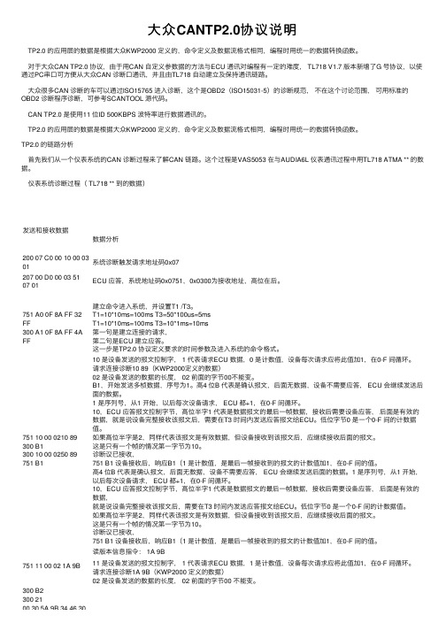
TP2.0 的链路分析⾸先我们从⼀个仪表系统的CAN 诊断过程来了解CAN 链路。
这个过程是VAS5053 在与AUDIA6L 仪表通讯过程中⽤TL718 ATMA ** 的数据。
仪表系统诊断过程( TL718 ** 到的数据)发送和接收数据数据分析200 07 C0 00 10 00 0301系统诊断触发请求地址码0x07207 00 D0 00 03 5107 01ECU 应答,系统地址码0x0751,0x0300为接收地址,⾼位在后。
751 A0 0F 8A FF 32 FF300 A1 0F 8A FF 4A FF 建⽴命令进⼊系统,并设置T1 /T3。
T1=10*10ms=100ms T3=50*100us=5msT1=10*10ms=100ms T3=10*1ms=10ms第⼀句是建⽴连接的请求,第⼆句是ECU 建⽴应答。
这⼀步是TP2.0 协议定义要求的时间参数及进⼊系统的命令格式。
751 10 00 0210 89 300 B1300 10 00 0250 89 751 B110 是设备发送的报⽂控制字, 1 代表请求ECU 数据,0 是计数值,设备每次请求应将此值加1,在0-F 间循环。
大众标准TL 203中文2015-02

金属件装饰性镀铬(Ni – Cr 镀层)本标准对钢、铜和铝材零部件以及锌压铸金属所进行的装饰性电镀Ni-Cr 镀层规定了技术要求,表面防护方式见表1。
用于汽车外部的零件,使用镀铬铝制或镀铬锌压铸材料需经大众品牌和奥迪AG实验室允许。
2.标记见 VW 137 50, 2 条在各自图纸材料范围内对表面防护范围内的防护方式数据的补充,对电镀镀层母体材料的补充,按 DIN EN 1456 的规定执行,例如: C45, Fe//Cu20/Ni25d/Crmc3 技术要求3.1 基本技术要求首次供货和更改的批准按 VW 011 55避免有害物质按 VW 911 01一次完整的试验所需零件约 10 件(每次都按试验规模确定)首次样品试验报告要补充下面的数据或说明:—零件号—涂漆工具,涂漆数据—涂漆时间—作业进程(作业时间,电流密度,温度,化学药剂供应厂商)—支架上的位置3.2 表面性状防护涂层不得有气泡,粗裂缝,伤处或其他损害规定的外观和/或附着能力以及抗腐蚀强度的缺陷。
电镀零件的表面不能有斑点或褪色。
零件的外貌(光泽程度和表面结构)必须悉为原试样。
若有必要,边界样本需按照汽车制造工厂质保部门的要求。
如果是符合专业要求的装配,也具备了适合的运输条件,那就不应该出现导致削弱功能和降低技术要求的涂层损害。
由于使用和装配而产生的微小形变也不得导致电镀镀层的分离。
电镀时的接触部位需经同意并记录在图纸内。
如果图纸上没有特别规定(例如用户视线可见范围或不可见范围),则电镀镀层对结构件的全部区域都是有效。
零部件需可追溯。
3.3 镀层结构所用镀层结构取决于母体材料,零部件在汽车中的位置及表面质量的不同要求。
a)表1中所述性能为最基础的要求,必须遵守b)由于复杂的几何结构导致的层结构偏离,需与大众AG和奥迪AG实验室协商,提供其他满足要的技术要求。
c)仅适用于三价电解质浴的铬镀层d)高光表面裂纹密度按PV 1058。
微孔表面气孔密度按PV1063镀层结构性能的测量要点需和供应商以及相关发行部门协商决定,同时记录在图纸内。
DTLD大众培训资料

文件 记录
文件1 文件2 记录1 记录2 记录3
…
…
特性..
特性..
产品特性
生产/检验
过程特性
存档清单
人、机、料、法、环、物流(标识) …
存档清单
需
确定 D零件
D特性
D工序
D设备
D人员
要 存 档
文
件
D零件清单
存档清单
清 单
存档资料 总成
标准
A
√
B
√
C
D
E
…
图纸
√ √
重要 度分 级表
√ √
DFMEA √
DTLD大众培训资料
一、D/TLD定义、概念、识别 二、存档清单和存档 三、D/TLD审核和自审
定义与概念
➢ 是法律法规的要求和大众集团的要求,在发生损害情况 和/或大众汽车集团要求下,供应商必须证明自己在防止 产品出现缺陷方面已采取了足够的措施。
注:当供应商提供的产品涉及到产品责任时,首先供应 商的管理者具有重大的责任,为此,供应商一方面必须在 产品开发/制造过程充分满足法律法规/大众集团的要求, 履行产品责任(“做”);另一方面,必须对相应的活动 进行记录和存档以满足举证责任需要(“记”和“存”) 。
“D零件”—有存档责任的 零件(安全系统零件、底 盘零件、拉杆、双头螺栓、 内饰件……)
“D特性”
“D特性”—是产品的关键特 性值,是“D项目”特性值 的控制范围(例:“D项目” 球销硬度HRC28~32)。
存档资料
需要存档资料
设计开发资料 例如:产品重要度分级 表、DFMEA、PFMEA 、控制计划、图纸、标 准、国家法规3C认证、 开发过程认可、产品认 可等;
大众标准清单
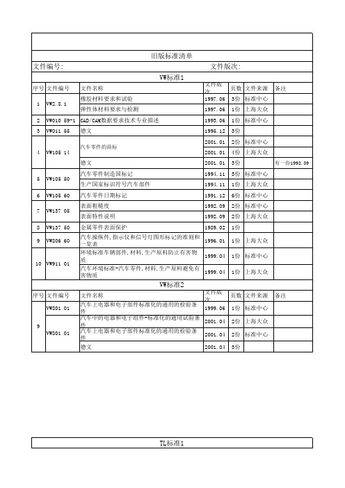
旧版标准清单
文件名称 用于汽车内饰件材料的油漆材料要求 在汽车内部装备材料上涂漆要求 德文 电镀铬塑料件材料要求 成型件的聚苯撑氧材料要求 泡沫胶带,双面粘贴的材料要求 聚丙烯车厢衬里:6个类型 德文
文件版次:
文件版 次
页数 文件来源 备注
1998.11 5份 标准中心
1998.11 1份 上海大众
文件版 次
页数 文件来源
1993.12 6份 标准中心
1993.12 2份 上海大众
1993.12 3份
1993.01 4份 上海大众
1993.01 1份 标准中心
备注
序号 文件编号 文件名称 1 DIN 53 505 橡胶,弹性体和塑料试验
DIN标准1
文件版 次
页数 文件来源 备注
1987.06 2份
1998.11 1份
1993.06 5份 标准中心
1987.11 7份 标准中心
1993.02 1份 标准中心
2002.05 1份
2002.05 1份
序号 文件编号 1 PV1303 2 PV 3900
PV标准1
文件名称 塑料膜,织物层氙弧同步曝光 检验规范-塑料薄膜,平幅织物氙弧灯连续照射 德文
汽车车厢内零部件气味试验
文件版 次
页数 文件来源
1999.06 1份 标准中心
汽车中的电器和电子组件-标准化的通用试验条 件
2001.04
2份 上海大众
汽车上电器和电子部件标准化的通用的检验条 件
2001.04 2份 标准中心
德文
2001.04 3份
备注26
2 TL528 3 TL520 13 4 TL520 18 5 TL523 88
大众汽车标准_VW 01055-Y
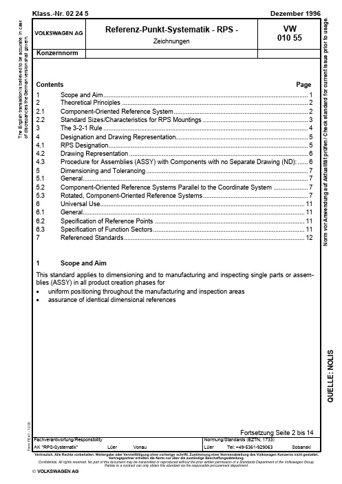
Vertragspartner erhalten die Norm nur über die zuständige Beschaffungsabteilung.Confidential. All rights reserved. No part of this document may be transmitted or reproduced without the prior written permission of a Standards Department of the Volkswagen Group.Parties to a contract can only obtain this standard via the responsible procurement department.© VOLKSWAGEN AGN o r m v o r A n w e n d u n g a u f A k t u a l i t ät p r üf e n / C h e c k s t a n d a r d f o r c u r r e n t i s s u e p r i o r t o u s a g e .T h e E n g l i s h t r a n s l a t i o n i s b e l i e v e d t o b e a c c u r a t e . I n c a s e o f d i s c r e p a n c i e s t h e G e r m a n v e r s i o n s h a l l g o v e r n .Q U E L L E : N O L I SSeite 2VW 010 55: 1996-122 Theoretical Principles2.1 Component-Oriented Reference SystemOne of the basic ideas forming the basis for the reference point system is the component-oriented coordinate system according to VW 010 52.A vehicle is dimensioned by means of a global coordinate system (mathematical vehicle coordinate system), the origin of which is defined to be in the center at the level of the front axle of a vehicle (see VW 010 59 Part 1; VW 010 52 is the binding reference for the vehicle coordinate system), Figure 1.A Vertical plane S Longitudinal center plane D Horizontal planeFigure 1. Global coordinate system for vehiclesStarting from the axes of this coordinate system, grid lines are spread out parallel to the axes. These grid lines, spaced 100 mm apart, theoretically penetrate the vehicle. These grid lines serve to find all points on the vehicle. In other words, they help to determine the position of each vehicle component. Dimensioning is also performed with the aid of these grid lines.The reference point system is based on a component-oriented reference system.The origin of the component reference system is defined by the intersection point of three refer-ence planes. The reference planes are formed via the RPS main mountings defined on the compo-nent.When several parts are assembled, these parts are toleranced with respect to each other.After the parts are joined, the ASSY is described by a combined component-oriented reference system. This is formedby adoption of one of the existing reference systems orby forming a new reference system using the existing reference points.The specification of the new reference system depends on the function of the ASSY.Seite 3VW 010 55: 1996-122.2 Standard Sizes/Characteristics for RPS MountingsMultiple-use location holes with high precision requirements must be adequately strong.In general, the standard sizes according to Table 1 and Table 2 shall be used. In case of holes in RPS surfaces, it must be ensured that the bearing surfaces are of adequate size and provide proc-ess assurance.The specified dimensions shall be projected – parallel to the axes – onto the component.Table 1.Recommended standard valuesFor further standard sizes see VW 010 77Designation Nominal dimen-sionTol.Graphical representationL o c at i o n h o l e s ,p l u g g a b l eRound hole see VW 01077101520Square25+16 x 2010 x 20Rectangle15 x 20+1Ø 15Ø 20S u r f a c e sCircleØ 25+11020E d g e sEdge length "a"25+1Table 2.Recommended standard valuesFor further standard sizes see VW 010 78Designation Nominal dimen-sion w x lTol.Graphical representationLong holeL o c a t i o n h o l e s ,p l u g g a b l eLong hole in angle positionsee VW 01078Seite 4VW 010 55: 1996-123 The 3-2-1 RuleEvery rigid body possesses six degrees of freedom in three-dimensional space: three translational degrees parallel to the axes of a reference system and three rotatory degrees around the axes, Figure 2.Figure 2. The degrees of freedom in three-dimensional spaceIn order to support a non-rotationally-symmetric body in a uniquely determinate manner, it must be fixed in all six possible directions of movement. The 3-2-1-rule provides for such unique fixing. It determines the following main-mounting distribution:E.g. 3 mountings in z direction2 mountings in y direction1 mounting in x directionImplementation of this rule is shown based on the following representation, Figure 3.Figure 3. Application of the 3-2-1 ruleThe three mountings in z direction restrict three degrees of freedom: translation in z direction and rotation around the x and y axes. The pin in the round hole prevents motion parallel to the axes in the x and y directions and, finally, the pin in the long hole prevents rotation around the z axis, Fig-ure 3.This rule applies equally to any other rigid component, even if its structure is much more complex. With a system of rigid bodies, the elements of which are interconnected by joints or guides, more than 6 degrees of freedom must be fixed using additional main mountings.For non-rigid components, additional support points must be defined for supporting the compo-nents according to RPS aspects.RPS 1 shall be the point that binds the most degrees of freedom.Seite 5VW 010 55: 1996-124 Designation and Drawing Representation4.1 RPS DesignationAll RPS points must be included in the part drawing.The designation is subdivided as follows:•Main mounting points=Capitals?H =Hole? F =Surface?T =Theoretical pointis the mean of two support points •Support points=Small letters?h =Hole? f =Surface?t =Theoretical pointis the mean of two support points •Mounting types?Location holes/pins=Code letter H,h?Surfaces/edges/ball/tip=Code letter F,f?Theoretical point=Code letter T,t •Fixing directions=Small letters?x, y, z for component-oriented reference systems parallelto the coordinate system?a, b, c for rotated, component-oriented reference systems Examples of designation:Fixing directionCode letter for surface as main mountingFixing directionsCode letter for hole as main mountingDesignation with numberingFixing directionCode letter for surface as main mountingDesignation with numberingFixing directionCode letter for surface as support pointDesignation with numberingNumbering begins with the RPS 1 point for each single part and for each assembly.Seite 6VW 010 55: 1996-124.2 Drawing RepresentationDrawing representation takes place according to the valid drawing guidelines.The RPS surfaces shall be identified by means of cross-hatching.If a part drawing does not exist yet, RPS Dimensions Sheet FE 515 1) shall be used.As soon as the part drawing exists, the specifications from the RPS Dimensions Sheet are adopted directly in the drawing or adopted in text macro NO-F23 2). Administration of these specifications in the text macro is mandatory.4.3 Procedure for Assemblies (ASSY) with Components with no Separate Drawing (ND): The RPS points for components with no drawing (ND) must be identified by specifying the item number or part number.A drawing exists for part 1; ND for parts 2 and 3, Figure 4.A RPS 1 Hxy; RPS 1 Hxy for Item 3S RPS 2 Hx only for Item 3D RPS 1 Hxy only for Item 2F RPS 2 Hy; RPS 2 Hy for Item 2Fig. 4ASSY with RPS pointsGraphical representation, not adopted in drawing1) Stored in design data administration system under FEO 000 5152) Stored in design data administration system under NOF 000 023Seite 7VW 010 55: 1996-12 5 Dimensioning and Tolerancing5.1 GeneralDimensions and tolerances can be entered directly in the drawing or via the table, Figure 5.The starting point for dimensioning the components is generally the origin of the reference system. Form and functional dimensions with tolerances shall always be referenced to the origin of the ref-erence system.Example: The holes within a hole group are dimensioned with respect to each other. The position of the hole group is dimensioned with respect to the reference planes.In the fixing direction, the main mountings are positioned without tolerance with respect to the vehi-cle coordinate system / reference system.The origin/reference point is shown in the drawing or table. If two or three fixing directions are bound at one point, tolerancing must be separated according to the hole or surface. In this case, the surface must be identified one line lower in the table. Here, the surface is set to zero in the tol-erance zone. In the line in which the hole is set to zero, the tolerance zone for the surface shall be identified with a horizontal line, see the table in Figure 5.The support-point tolerances shall be defined according to the requirements.5.2 Component-Oriented Reference Systems Parallel to the Coordinate SystemThe origin of the reference system is defined without tolerances in the global vehicle coordinate system by means of a translation, Figure 55.3 Rotated, Component-Oriented Reference SystemsWith rotated reference systems, the theoretical angles of rotation must be specified in RPS Dimen-sions Sheet FE 515 1) or in the drawing table text macro NO-F23 2).If there are several angles of rotation, the angle specification and thus the sequence of rotations shall be obtained from the drawing. "See drawing" must be added to the table instead of the angle entry.The position of the reference point is determined by means of its x, y and z coordinates in the global vehicle coordinate system.Angles of rotation around the x, y and z axes are entered using mathematically positive or negative values. Positive angles are specified counterclockwise and negative angles clockwise.In the coordinate system, the horizontal axis is assigned an angle of zero.Nominal dimensions and tolerances are specified in a, b and c values in the RPS table.The fixing directions of the RPS points are specified as a, b and c values in the table and/or draw-ing, e.g. RPS 1 HabFc, Figure 6 and Figure 7.1), 2)see page 6Seite 8VW 010 55: 1996-12A if necessaryFig. 5Dimensioning with text macro NO–F23Seite 9VW 010 55: 1996-12A Reference point S View RSeite 10VW 010 55: 1996-12A Reference point S View R6 Universal Use6.1 GeneralThe purpose of the RPS is to provide process assurance/capability and repeat accuracy for the procedures in order to make them independent of setting work performed by the worker.The reference points must be used in all manufacturing, assembly, inspection and installation pro-cesses.In case of self-contained function sectors such as the side panel tank flap, a reference change in combination with functional dimensions to RPS planes is permissible.Prior to the specification of RPS points, it is absolutely necessary to define the functions of the sin-gle part and the relevant assemblies with their required functional tolerances.Reference points that were established at the beginning of a process must be kept for as long as possible. In order to avoid changes to arranged reference points, they are jointly defined – as early as possible in the design and development process – in consultation with all departments partici-pating in the production process.Reference points must be positioned at stable areas of a component that will remain unchanged even in further development and/or production processes.Reference points on components that move relative to the body during driving operation can be considered according to the 3-2-1 rule only in the actual design position.The RPS points on components that are used several times in vehicles and thus have multiple ref-erences to the global coordinate system can be shown without a global coordinate reference in the technical drawing.The reference point system is equally oriented toward the production process, toward the function sectors and toward the strategic quality goals, e.g. audit, process capability.6.2 Specification of Reference PointsParallelism to the coordinate system (holes and surfaces) must be observed when entering the reference points. In the case of rotated systems, parallelism to the reference planes must be o b-served.The RPS points must be produced in the tool sequence in which the greatest dimensional stability is attained.Whenever possible, reference points must be produced with a standardized shape (hole, surface), which must be defined in detail.If holes cannot be made in a component, surfaces or edges must be used to specify reference points.In the case of COP parts (transfer parts), the respective reference-point positions arise in the ASSY.6.3 Specification of Function SectorsUse of the RPS on a complex portion of the vehicle such as the dashboard requires a structure that addresses the development and design engineering systems and includes all parts, single parts and assemblies.A function sector includes all components in the visible and covered areas that directly affect their surroundings with their function points.The specification of reference planes depends on the spatial and geometric position relationship of a component with its surroundings.The reference planes are identical for a function sector. In other words, components or component groups and the surroundings have the same starting basis, Figure 8.A Dashboard ASSY function sector S Airbag function sectorD Center-vent function sector F Air outlet vent function sector FS Fig. 87 Referenced StandardsVW 010 52VW 010 59 T1VW 010 77VW 010 78。
大众公司的D TLD

D/TLD大众公司的D/TLD是什么含义?7.6 技术文件的标识在大众集团中有两种同级别的标识符号(D和TLD)。
D-标识:如果尺寸、文字说明涉及到法规及企业内部的制造规范的话,在图纸,TL-VW等技术文件中使用D标识。
为了标示出存档责任,在标题栏(图纸说明栏的“D标识”区域或者“Sicherh.Dok./SafetyDoc.”区域)中标出D。
技术文件中的尺寸或者其它D特性将用两端限位的横杠( ) 标识出来。
TLD-标识:在标题栏(图纸说明栏)的“Sicherh.Dok./SafetyDoc.”区域中不出现D,而是出现了TLD。
此时,在“技术文件”区域中将出现相应的TLD-号码,这些号码所表示的技术文件中包含了必须存档的技术特性和对法规的说明。
特性或法规上的横杠符号则没有了。
在TLD-汇编中只列出了重要的具有概括性的技术供货条件。
如果在这些技术供货条件中还要参阅其它的技术供货条件,那么其它技术供货条件也同样属于存档责任文件。
11. 要求条例验证(D/TLD-零件)1 技术资料/ 提供证据在产品和过程诞生的各个阶段,以及在批量生产中的一些专门的文件和质量证据对于履行存档义务是特别重要的。
供应商必须对技术资料/文件进行无遗漏的收集、归纳整理和存档。
要通过落实、满足和保持顾客特别要求的存档责任特性来实现质量证据。
这种工作程序也要相应地应用于分供方。
供应商有义务,从自己的经验中总结出其它的重要特性,补充性地包括进存档义务之中,而这些特性有可能没有被顾客作为存档责任规定下来。
1.1 是否实行了文件管理程序?1.2 D/TLD零件的技术资料是否是最新有效状态,是否有D/TLD零件标识,是否对D/TLD-特性作了专门的标记?有些特性在大众/奥迪的资料中没有作为D/TLD-特性标明出来,而零件制造厂认为是与安全有关的,零件制造厂是否在产品责任范围之内对这些特性也进行了记录和存档?1.4 零件制造厂是否可靠地保存了制造和检验的技术资料,存档期至少15年(与法规“危险材料使用规定”中§18[3]有关的资料至少存档30年)?1.5 全部关键的数据是否包含在存档文件之中?存档方法是否适合于随时迅速地查阅到每一份资料?1.7 对D-特性有影响的分供方是否也承担了相应的存档责任的义务?1.8 是否评定了对D-特性有影响的分供方?是否有证据地表明确保了各项要求?1.9是否有欧共体安全数据表(EG-Sicherheitsdatenblatt),化学品法,危险材料使用规定(Gefahrstoffverordnung)和化学品-禁止使用规定(Chemikalien-Verbotsverordnung),是否新版本,是否明确规定了职责和责任人?1.1 是否实行了文件管理程序?要求/说明所有的D/TLD零件的资料,包括首次认可和更改认可的质量保证证据都要按照程序步骤进行管理。