Implementation of Controller Area Network (CAN) Bus (Building Automation)
USB2CAN模块用户手册说明书

USB2CAN MODULE User ManualUSB2CAN module is a‘plug and play’and bi-directional port powered USB to CAN converter which realizes long-distance communication between your Raspberry Pi/SBC/PC and other devices stably though CAN-Bus connection.With small size and convenient operation,It’s a cost-effective solution that are safe and reliable for all your data-conversion/device-protection applications for any experienced engineer interfacing to expensive industrial equipment yet simple enough for home use by an amateur hobbyist.USB2CAN can also be applied to obtain the data of car via the OBD connector,but you need to configured and secondary development by yourself.2.patible with Raspberry Pi Zero(W)/Pi3B+/PI4/Beaglebone/Tinker Board and any single board computer.2.Plug and Play USB device.No external power required.Support wider CAN baud rate,From 20Kbps to1Mbps can be programmed arbitrarily.3.On board STM32F0microcontroller,high speed data transfer with DMA technique.Support for CAN bus2.0A and2.0B specification.4.Power supply isolation,signal input/output isolation,Built-in surge and static protection.120 Ohm resistor selectable jumper feature.es with C/Python demos of Socket-CAN,detailed user manual and friendly technology support.4.1CAN connectorPinout4.2120Ohm Resistor Setting.A High-speed CAN bus (ISO 11898-2)must be terminated on both ends with 120Ohms.The USB2CAN module with a on-board 120Ωselectablejumer.Disable 120Ohm Resistor.Enable120Ohm Resistor.4.3LEDIndicate5.Run USB2CAN Test DemoUSB2CAN module can run properly without any additional driver request on all Linux system since version3.9.such as Ubuntu,Debian and Raspbian.If you meet problems in older system, You need to reconfigure the kernel drivers.Enable‘gs_usb.c’and install‘gs_usb.ko’into system. So notice that if you only compile this drivers,It may fail to load in system.At this time,compile fully with new configure.You can test the USB2CAN module any single board computer or PC with the right Linux version. We take Raspberry Pi4as an example to show you how to run the C/Python and can-utils demo.5.1Preparatory work5.1.1ConnectionThere are two way to test the USB2CAN module.One is plug two USB2CAN module into the USB Host of each Raspberry Pi.The other is plug two USB2CAN into one Raspberry Pi.But the codes and commands are a little bit different.And then connect the CAN_H pin and CAN_L pin to eachother.No GND pin connection requirement.Methods A Methods BUse two Raspberry Pi to test USB2CAN Use one Raspberry Pi to test USB2CAN 5.1.2ifconfig-aType command‘ifconfig-a’to check‘can0’device is available in system.If you plug two USB2CAN into one Raspberry PI,You will see one more‘can1’device.5.1.3demsgYou can type command‘demsg’for see more information about USB2CAN module at the bottom.5.2Use can-utils toolThis tool is a very easy way to test CAN commuincation by only type two command.5.2.1Install Toolssudo apt-get install can-utils5.2.2Initialize CAN portsudo ip link set can0type can bitrate125000sudo ifconfig can0up5.2.3Set one as receivercandump can05.2.4Set the other as sendercansend can0123#12345678905.2.5Test two module on one Raspberry PiDo as above steps,set‘can0’as receiver and‘can1’as sender.5.3Run C Demo(1)Load C Demo named‘usb2cantest’from our Wiki and up-zip it to the desktop of Rasbian./wiki/doku.php?id=usb_canOr /wiki/doku.php(2)Go to folder named‘c’and change the permissions.chmod-R a+x*(3)Set one as receiver,execute following commands in serial terminal.Now this Raspberry pi is blocked../can0_receive(4)Set the other Pi as sender,execute following commands../can0_send(5)You should see that the receiver has received the packet.(6)You also can plug two USB2CAN module on one Raspberry PI board to test.You should see two can socket“can0”and“can1”devices.So notice that you need to change“can0”to“can1”when you use“can1”device.5.4Run Python3DemoDownload Python Demo named‘python3’from our Wiki and up-zip it to Desktop(or wherever you want put it)./wiki/doku.php?id=usb_canOr /wiki/doku.phpThere are three files in the folder.‘send.py’and‘receive.py’is for you use two Raspberry Pi to test,and‘test.py’is for you use one Raspberry Pi and two USB2CAN module to test.(1)Check the Python version of your Raspbian.Python3.7.3default in2019-09-26-Raspbian.img. Our Demo can run on any Python3version.python3-V(2)If you can’t find the Python3in system.Install the Python3sudo apt-get install python3-pip(3)Install Python CAN library.sudo pip3install python-can(4)Set one Raspberry Pi as receiver.sudo python3receive.py(5)Set the other as sender.sudo python3receive.py(6)You will see the data received.(7)If you use one Raspberry Pi and two USB2CAN modeule for testing.Run‘test.py’and check the result.sudo python3test.py6.Now with previous demo’s code to show you how to program socket can in Raspbian with C and Python.The socket can is an implementation of CAN protocols(Controller Area Network)for Linux.CAN is a networking technology which has widespread use in automation,embedded devices,and automotive fields.While there have been other CAN implementations for Linux based on character devices,Socket CAN uses the Berkeley socket API,the Linux network stack and implements the CAN device drivers as network interfaces.The CAN socket API has been designed as similar as possible to the TCP/IP protocols to allow programmers,familiar with network programming,to easily learn how to use CAN sockets.For more Socket CAN detail please refer to below link:https:///doc/Documentation/networking/can.txt6.1Programming in C6.1.1For Sender’s codes(1):Create the socket,If an error occurs then the return result is-1.(2):Locate the interface to“can0”or other name you wish to use.The name will show when you execute“./ifconfig–a”.(3):Bind the socket to“can0”.(4):Disable sender’s filtering rules,this program only send message do not receive packets.(5):Assembly data to send.(6):Send message to the can bus.You can use the return value of write()to check whether all data has been sent successfully.(7):Close can0device and disable socket.6.2.3For Receiver’s codes(1)step1and(2)is same as Sender’s code.(3):It’s different from Sender’s.(4):Define receive filter rules,we can set more than one filters rule。
基于时间触发的TTCAN协议
TI'CAN中的时间触 发 通信 是基 于校 时基 准消息 (reference message)完 成 的 ,此 基 准 消 息 由 TI'CAN 网 络 中 的计 时 主机 (time master,确 定 网络 时 间 基 准 的 控 制 节点 )定 时发送 。在 TI'CAN 网络 中最 多 可 以有 8个 计 时主机 ,由各 自识别 符决 定优 先级 。同一 时间 只有 一 个 计 时 主机 发 送 基 准 消 息 ,当 前 计 时 主 机 工 作 发 生 异常 时由备份计 时主机发送基准消息” 。
1 TTCAN 简 介
TI'CAN协议 是一 种在 ISO 1 1898.1规定 的 CAN数据 链路层顶部之上 的高层协议 ,可基 于标准 CAN 物理层 协议实现,如 ISO 19898—2(高速收发协议 )、ISO 19898.3(容 错低速协议)。TI'CAN扩展协议分为两层 ,第一层子协议
年推出,目前在 汽车电子 中广泛应用 。现行 的 CAN2.0 明只在第二层子协议中实现的服务。
协议定义了物理层和数据链路层协议规范 ,是基于事件 触发的通信协议 。CAN2.0协议提供 的总线仲裁机制保 证了所有消息都能无破坏地传输 ,但是会 导致一些消息 传输的延时。在一些实时 l生要求较高的应用 中,迫切需 要提供一种服务 以保 障安全相关的消息传输不受 总线 上 其 他 待 传 输 消 息 的 影 响。TI'CAN(time.triggered CAN)协 议 正 是 应 这 种 需 求 而 提 出并 发 展 起 来 的 。 TI'CAN对 CAN协议进行 了扩展 ,提供 时间触 发机制 以 提高通信 实时性 。TI'CAN的研究 始于 2000年 ,现 已成 为 CAN标准 的 第 4部 分 ISO 11898.4,该 标 准 目前 处 于 CD(委 员 会草 案 )阶段 。
Front End Controllers 7.1 产品说明书
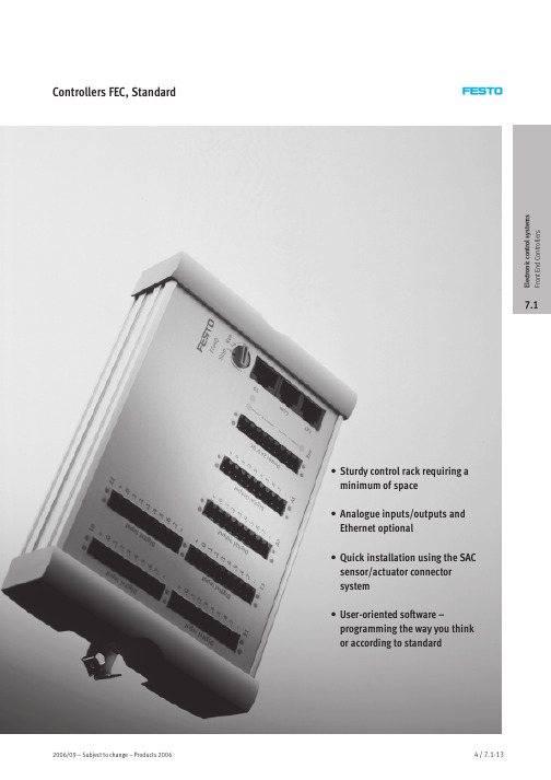
Controllers FEC,Standard•Sturdy control rack requiring a minimum of space•Analogue inputs/outputs and Ethernet optional•Quick installation using the SAC sensor/actuator connector system•User-oriented software–programming the way you think or according to standard ElectroniccontrolsystemsFrontEndControllers 7.1Controllers FEC,StandardKeyfeaturesThe installation-saving controller The FEC Standard is not just a new mini controller.It shows that there is still room for innovation in mini controllers at the start of the new millennium.With its robust extruded aluminium housing,it demonstrates thatcompact design and toughness can go hand in hand.Its connector system is accessible from the front,ensuring no wastage of space within control cabinets.And the sensor/actuator connector system SAC,making its world premiere in this product,very largely replaces terminal strips in the I/O area.This means that control cabinets with FEC Standard have a decisive advantage:Up to 50%less space required,and up to 40%less time.Thanks to the integration of a high-speed counter into every CPU,this mini controller is well able to carry out counting and simple positioning operations.Additionally,the optional analogue inputs/outputs turn a smart mini controller into a smart process controller.The two serial interfaces in every CPU make the FEC Standard into a talented communicator which allows program-ming via one interface and operation and monitoring via the other,at the same time.The leading concept in communication today is Ethernet,the “network of networks”.This can of course be integrated intoFEC Standard as an option.After all,smart automation technologydemands smart network technology.With Ethernet and a web server,the FEC Standard paves the way for the visualisation technology of tomorrow:Controller surfing.E l e c t r o n i c c o n t r o l s y s t e m sF r o n t E n d C o n t r o l l e r s7.1Controllers FEC,StandardKey featuresHardwareThe FEC Standard has a clip for a top-hat rail and corner holes for bolt-mounting using a mounting plate.All connections are accessible from the front;there is no need for additional space for connections from above or below.Power supplyThe FEC Standard is poweredexclusively via 24V DC as per modern control cabinet technology.24V DC (+25%/-15%)power supply for the controller itself,24V DC (+/–25%)power supply for the input signals,positive switching,24V DC output signals 400mA,proof against short-circuits and low-resistance loads.The analogue inputs/outputs are 0(4)...20mA I/Os,12bitresolution.Serial interfacesEvery FEC Standard is equipped with two serial interfaces –COM and EXT.These are universal TTL interfaces with a maximum data transmission rate of 115kbits/s.Depending on requirements,the interfaces can be used as RS232c (SM14or SM15)or RS485(SM35)interfaces.Adapters should be ordered separately.The COM interface is generally used together with the SM14for program-ming,while the EXT interface can be used for an MMI device,a modem or other devices with a serial interface.Ethernet interfaceThe FEC Standard versions with an Ethernet interface incorporate an Ethernet 10BaseT interface with an RJ45connection and a data transmission rate of 10Mbits/s.A combined “Link/Active”LEDindicates the connection status.The FEC Standard supports datacommunication and programming/troubleshooting via the Ethernetinterface.ProgrammingThe FEC Standard is programmed using FST.FST is a unique programming language rich in tradition and very easy to use,allowing “programming the way you think”:IF...THEN...ELSEFST also supports STEP operation for sequence programming.FST can be used for programming via Ethernet;a web server is alsoavailable.E l e c t r o n i c c o n t r o l s y s t e m sF r o n t E n d C o n t r o l l e r s7.1Controllers FEC,StandardKey featuresThe sensor/actuatorconnectorTogether with the FEC Standard,we are introducing an innovative new installation concept,the sensor/actuator connector SAC.Thisconnector combines three functions in a very compact design:•Connection of inputs,outputs and power supply•Status signal by means of an LED •Replaces terminal strip for sensors andactuatorsThe three-wire version of theconnector has internally connected straps for 0V and 24V DC.This allows any sensor (up to 3wires)or actuator (up to the maximumpermissible output current)to be feddirectly to the connector.There is no need for a terminal strip for sensors and actuators.This allows space savings in control cabinets of up to 50%.The SAC uses a tension-spring contact system.This means no need for screw connections.Solid wires can simply be pushed into the connector,while in the case of finely-stranded wire,all that is necessary is to open the contact by pressing on the relevant pin and then introduce the wire.Cable end sleeves can be used if desired but are not essential.The tension-spring system and the fact that no terminal strip between the controller and sensors/actuator is required means that a time saving of up to 40%can be achieved during installation.The pin assignment for the I/O panel is simple and is always the same:Pin 1+24V DC Pin 2Bit 0Pin 3Bit 1Pin 4Bit 2Pin 5Bit 3Pin 6Bit 4Pin 7Bit 5Pin 8Bit 6Pin 9Bit 7Pin 100VThe power supply for the LEDs istaken from the signal pins in the connector.This means that the entire input assignment can be checked without acontroller.E l e c t r o n i c c o n t r o l s y s t e m sF r o n t E n d C o n t r o l l e r s7.1Controllers FEC,StandardKey featuresProgramming withFSTProgramming the way you think How do we describe a machine?“When a workpiece reaches here,this cylinder should advance.”How does the software interpretthis?Or does your machine work through a sequence step by step?“First,this cylinder must advance and stop the workpiece,and then the workpiece must be clamped,and thenfinally...”How,for example,can we sub-divide a task?Program 0:Organisation Program 1:Set-up program Program 2:AutomationprogramProgram 3:Fault monitoring Program 4:Manual operation ...Program 63:TroubleshootingprogramHow does one controller communicate with another?Every controller with Ethernet can send and receive data from every other controller within a network –no matter whether this data relates to inputs,outputs,flags or registers.Central programming of distributed controllersEvery controller within a network can be programmed from any desired network interface.A controller on the World Wide Web FST incorporates a web server –the Internet and the world of automationmeet.Programming just couldn’t beeasier.E l e c t r o n i c c o n t r o l s y s t e m sF r o n t E n d C o n t r o l l e r s7.1Controllers FEC,StandardProduct range overview The FECStandardE l e c t r o n i c c o n t r o l s y s t e m sF r o n t E n d C o n t r o l l e r s7.1Controllers FEC,StandardProduct range overviewThe principle of the FECStandard11235461In each case 16digital inputs,24V DC,positive-switching 2Optionally:3analogue inputs/1analogue output3In each case 8digital outputs 4Power supply5Rotary RUN/STOP switch 62serial interfaces,option ofEthernetE l e c t r o n i c c o n t r o l s y s t e m sF r o n t E n d C o n t r o l l e r s7.1Controllers FEC,StandardTechnical data General technical dataFEC-FC400FEC-FC440FEC-FC600FEC-FC640FEC-FC660Max.operating temperature0...55°C Max.transport and storage temperature –25...+70°CRel.humidity 0...95%(non condensing)Operating voltage 24V DC +25%/–15%Power consumption <5W Degree of protection IP20Degree of protection Degree of protection III.Power pack in accordance with IEC 742/EN60742/VDE0551/PELV with at least 4kV insulation resistance or switched-mode power supplies with safety isolation as defined by EN 60950/VDE 0805are required Certification C-TickI/O connection Tension spring connector EMC EN 61000-6-4Digital inputsFEC-FC400FEC-FC440FEC-FC600FEC-FC640FEC-FC660Number1632Number of above usable as high-speed inputs (max.2kHz)2Minimum pulse length for TRUE:250µs,Minimum pause length for FALSE:250µs Input voltage/current 24V DC,typical 5mA Nominal value for TRUE 15V DC min.Nominal value for FALSE 5V DC max.Input signal delay Typical 5msElectrical isolationYes,via optocoupler Permissible length of connecting cable Max.30mStatus display via LED Optional,in connectorAnalogue inputsFEC-FC400FEC-FC440FEC-FC600FEC-FC640FEC-FC660Number 03Signal range 0(4)...20mA Resolution12bit,±3LSB Conversion time10ms Permissible length of connecting cable Max.30mDigital outputsFEC-FC400FEC-FC440FEC-FC600FEC-FC640FEC-FC660Number 816ContactsTransistorCurrent/voltage 24V DC,max.400mA Short circuit proofYesProof against low-resistance loads Yes,up to 5W Overload-proof YesElectrical isolation Yes,via optocoupler Switching speedMax.1kHzElectrical isolation in groups Yes,in each case 1byte Maximum group current 3.2A Switching cyclesUnlimitedStatus display via LED Optional,in connectorAnalogue outputsFEC-FC400FEC-FC440FEC-FC600FEC-FC640FEC-FC660Number 01Signal range 0(4)...20mA Resolution12bit Conversion time 10ms Max.load resistance700ΩE l e c t r o n i c c o n t r o l s y s t e m sF r o n t E n d C o n t r o l l e r s7.1Controllers FEC,StandardTechnical dataRotary switchFEC-FC400FEC-FC440FEC-FC600FEC-FC640FEC-FC660 Number1Positions16STOP/RUN0=Stop1...F=RUNSerial interfaceFEC-FC400FEC-FC440FEC-FC600FEC-FC640FEC-FC660 Number2Connection RJ12plug socketFeatures Serial,asynchronous,TTL level,no electrical isolationUse as RS232c PS1-SM14or PS1-SM15requiredTerminal assignment SM14/15Transmit,receive,RTS,CTSUse as RS485PS1-SM35requiredUse as programming interface9600bits/s,8/N/1Use as universal interface:COM300...9600bits/s,7N1,7E1,7O1,8N1,8E1,8O1Use as universal interface:EXT300...115,000bits/s,7N1,7E1,7O1,8N1,8E1,8O1SAC connectorFEC-FC400FEC-FC440FEC-FC600FEC-FC640FEC-FC660 Number of connectors required44778 Insulating material PBT,colour blackTemperature range PS1-SAC10/SAC30:–20...+100°Cp gPS1-SAC11/SAC31:–20...+75°CFlammability class V-0Grid dimension 3.5mmConnector system Spring connectionInsulation-stripping length9...10mmClamping range0.05...1.5mm2Single-conductor H05(07)V-U0.20...1.5mm2Multi-stranded without cable end sleeves0.5...1.5mm2Multi-stranded with cable end sleeves inaccordance with DIN46228/10.5...1.5mm2Multi-stranded hot-dip galvanized0.05...0.2mm2Current rating for strap contacts16ACurrent rating for individual contacts2A(max.6A per contact,please note the admissible loads for distributor board and supply contacts)EthernetFEC-FC400FEC-FC440FEC-FC600FEC-FC640FEC-FC660 Number01011Bus interface IEEE802.3(10BaseT)Data transmission speed10Mbits/sConnector RJ45Supported protocols TCP/IP,EasyIP,httpOPC server upon requestDDE server Yes,for EasyIP ElectroniccontrolsystemsFrontEndControllers 7.1Controllers FEC,StandardTechnical data ProgrammingFSTProgramming languages Version 4.02:statement list(with version 3.2:statement list and ladder diagram in German and English)Working languageGerman and English Number of programs and tasks per project64(0...63)Permissible input addresses0 (255)addressable as bits or words Permissible output addresses 0 (255)addressable as bits or words Number of flags10,000(0...9999),addressable as bits or wordsNumber of timers and counters 256(0...255)in each case,with 1status bit,1setpoint and 1actual value Number of registers (words)0 (255)addressable as words Programming interfaceRS232or Ethernet Number of different operations >28Subroutine Up to 200different subroutines per project C/C++Yes,for modules and drivers File handling Yes RS232c Yes ABG Yes FEDYesWeb server Yes (FST from version 4)RemanenceFlag words 0...255Register 0 (126)Timer and counter preselects and counter words 0...127PasswordPerformance1.6ms/1k instructions approx.E l e c t r o n i c c o n t r o l s y s t e m sF r o n t E n d C o n t r o l l e r s7.1Controllers FEC,Standard Technical dataType L1L2FEC-FC4…132.1114.2FEC-FC6…174.7156.8Ordering data–The FEC Standard with FST programmingDesignation Features Part No.TypeIPC controller16I/8O183862FEC-FC400-FST 16I/8O,Ethernet185205FEC-FC440-FST32I/16O191449FEC-FC600-FST32I/16O,Ethernet191450FEC-FC640-FST32I/16O,3/1analogue I/Os,Ethernet197157FEC-FC660-FST ElectroniccontrolsystemsFrontEndControllers 7.12006/0920064/7.1-2320062006/094/7.1-24Controllers FEC,StandardTechnical dataOrdering data –Connectors for the FEC Standard Designation Features Part No.TypePlug 1-row,no LED,tension-spring system 197159PS1-SAC10-10POL Plug 1-row,with LED,tension-spring system 197160PS1-SAC11-10POL+LED Plug 3-row,no LED,tension-spring system 197161PS1-SAC30-30POL Plug3-row,with LED,tension-spring system197162PS1-SAC31-30POL+LEDOrdering data –Cables for the FEC Standard Designation Features Part No.TypeProgramming cable RS232adapter for programming from PC,complete with neutral modem cable 188935PS1-SM14-RS232Converter RS232adapter for connection of any desired devices with a serial interface,with top-hat-rail clip,no neutral modem or RS232cable 192681PS1-SM15-RS232Converter RS485adapter,with top-hat-rail clip 193390PS1-SM35-RS485CableNeutral modem cable160786PS1-ZK11-NULLMODEM-1,5M Earthing setEarthing set for earthing of cable screening via the H-rail526683FEC-ZE30Ordering data –Display and operating units Designation Features Part No.Type Operator unitDisplay and operating unit,LCD with 4lines,20characters each,illuminatedbackground,4function keys,real-time clock and expansion interface,e.g.Ethernet533531FED-50Operator unit Display and operating unit,LCD with 4lines,20characters each,illuminated background,12function keys,numeric keypad,real-time clock and expansion interface,e.g.Ethernet533532FED-90Fieldbus interface Ethernet interface module for FED 533533FEDZ-IET Programming cable Programming cable for FED533534FEDZ-PC Cable Connecting cable FEC (RJ12,COM and EXT)to FED189432FEC-KBG6Ordering data –Software and manuals for the FEC Standard Designation Features Part No.TypeProgramming softwareFST software version4.X on CD,manuals on CD191440PS1-FST2-CD-WIN g g FST software version 4.1on CD with manual DIN A5in German 537927P .SW-FST4-CD-DE FST software version 4.1on CD with manual DIN A5in English 537928P .SW-FST4-CD-EN ManualSystem manual FEC Standard,German 525368P .BE-FEC-S-SYS-DE System manual FEC Standard,English525369P .BE-FEC-S-SYS-ENE l e c t r o n i c c o n t r o l s y s t e m sF r o n t E n d C o n t r o l l e r s7.1。
小区道路工程施工方案

工程概况为完善今后工业城区内的路网及基础设施的建设而开设3#大门。
其主要内容包括:道路工程、大门设置、市政绿化铲除工程等.本工程计划工期20日历天.第一节道路工程一号路位于东北侧呈西北走向;Ⅱ号路与一号路相交呈南北走向(双路面,中间填土);道路设计为城市次干路标准,道路施工中线为规划永中。
1、纵断面形式:小区道路纵断面设计,主要依据现况地势、相交道路高程及道路两侧建筑散水高程控制.2、横断面形式:小区道路采用两幅路的横断面型式,两上两下。
其中,中央分隔带宽度随施工道路延伸而不同,机动车道宽为7.3m,路肩一边为2.5米,另一侧为1。
5米。
3、道路结构:按城市次干路(2)级标准,机动车道结构厚为50㎝。
10%水泥石粉渣150mm厚压路机碾压开山石渣分层碾压400mm厚,密实度≥95%路槽以下0。
8米,密实度≥95%0。
8米以下,密实度≥93%(重型击实标准)设计道路路拱曲线均为直线型,横坡为1%两面坡。
⑴清表:场内表层植被土及苗木需首先清除,采用推土机、挖机辅以人工配合,清理掘除施工范围内的表土、草皮、树木、树根、垃圾等不适材料。
清表(淤)土方量较多,只能采取弃土方案,因工程在雨季施工,为确保清淤效果,防止施工中水土流失。
派人工在低洼及清淤地段开挖满足排水需要和防止水土流失的盲沟(原路基无排水沟地段),清淤地段两侧挖1。
0*1。
0m的排水沟,中间挖20cm*20cm 的网格状排水沟与两侧排水接通,开挖深度大于清淤深度20cm以上,并保证其排水顺畅.根据本工程总工期要求和现场情况及工程特点,充分利用现场有利条件,合理按排作业面和进度,做好施工部署,并在人力、机械设备、材料、技术上提供有力保障,以做到集中优势、合理布置、重点突破,达到保质、按期完成施工任务的目的.3、填土3.1、施工工艺:工艺流程基坑底地坪上清理→检验土质→分层铺上→分层夯打→碾压密实→检验密实度→修整找平验收3。
1.1、填土前,应将基底表面上的树根、垃圾等杂物都处理完毕,清除干净。
can通信协议解析与实现 英文

can通信协议解析与实现英文Analysis and Implementation of CAN Communication ProtocolI. IntroductionCAN (Controller Area Network) is a communication protocol used in automotive and other industrial applications. It provides a way of reliable data transmission and enables real-time communication between multiple nodes. This article analyzes the CAN communication protocol and explores its implementation.II. CAN Protocol Analysis1. Physical LayerThe physical layer of CAN defines the transmission of signals, including voltage, current and transmission rate. CAN bus uses differential signal transmission, which can effectively resist external interference and ensure reliable data transmission.2. Data Link LayerThe data link layer is the core of the CAN communication protocol, which defines the rules and mechanisms of data transmission. The CAN bus uses a master-slave structured communication method. The nodes compete for the right to use the bus. When a node obtains the right, it sends a data frame containing identifier, data and check code. Other nodes receive the frame and judge whether to receive it based on the identifier.3. Application LayerThe application layer is the highest layer of the CAN protocol, which defines the specific content and format of data frames. According to different application scenarios, the CAN bus supports multiple application layer protocols, such as CANopen, SAE J1939, etc. These protocols define specific formats and contents of data frames, as well as the communication rules and interactions between nodes.III. CAN Protocol Implementation1. Hardware ImplementationThe hardware implementation of the CAN protocol requires the use of dedicated CAN controllers and transceivers. The CAN controller is responsible for packing/unpacking data and controlling the transmission process. The transceiver is responsible for transmitting data from the CAN controller onto the bus or receiving it from the bus and passing it to the controller. The key is to select appropriate CAN controllers and transceivers and connect them correctly to the bus.2. Software ImplementationSoftware implementation is an important part of enabling CAN communication. The drivers need to be written to control the CAN controller and transceiver. The drivers interact with the operating system to accomplish sending and receiving data. Application programs are also needed to utilize CAN communication, e.g. to enable communication between nodes by sending and receiving data frames.IV. ConclusionThis article analyzes the CAN communication protocol and discusses its implementation. CAN communication features high reliability, real-timecapability and flexibility, making it suitable for automotive and industrial applications. By thoroughly understanding the CAN principles and implementation, we can better apply it to solve real-world communication problems.一、引言CAN(Controller Area Network)是一种用于汽车和其他工业领域的通信协议。
Inovance H2U Series PLC用户手册说明书
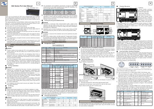
1423H2U Series PLC User ManualCode: 19010034 V2.0Thank you for purchasing the H2U series programmable logic controller (PLC) independently developed by Inovance Control Technology Co., Ltd. Read the manual carefully to be familiar with the product features and be able to use the product safely.This manual describes the specification, features and usage of the H2U series PLC. For the developing environment and design method of user programs, see the Autoshop On-line Help of Inovance.The H2U series PLC has the following features:◆The built-in program memory space reaches up to 16K steps.◆The internal large-capacity power supply can directly apply power tosensors, HMI, and external auxiliary relays.◆It provides multiple high-speed I/O terminals, and has rich motion andpositioning control functions.◆It has four independent communication ports and supports variouscommunication protocols including Modbus, facilitating system integration.◆The comprehensive encryption function protects intellectual propertyrights of the user.◆It comes with fast execution speed and supports up to 128subprograms and 21 interrupt subprograms. Each subprogram has the parameter call and independent password security functions.Safety Information and PrecautionsIn Design◆Provide a safety circuit outside the PLC in the application so that thecontrol system can still work safely even if external power failure or PLC fault occurs.◆In the external circuit of the PLC, an emergency stop circuit, aprotection circuit, an interlock circuit of forward/reverse rotation operation, and position upper/lower limit interlock circuit are necessary to prevent equipment damage ◆The PLC is designed for indoor electric environment and is installed in an overvoltage category 2 environment. A lightning protection device must be installed for the power supply system, so that lighteningovervoltage is not applied on terminals of the PLC, avoiding damage to the equipment.During Installation◆Install the PLC in places free from dust, oil smoke, conducting dust,corrosive gas, combustible gas, high temperature, condensation, wind & rain, vibration and shock. In addition, electric shock, fi re, malfunction may also cause damage and deterioration to the equipment.◆During screw hole processing and wiring, ensure that no metal filingand cable end fall into the ventilation hole of the controller, because such stuff may cause a fi re, fault, or malfunction.◆After installation of the newly purchased PLC is complete, ensure thatthere is no foreign stuff on the surface of ventilation. Failure to comply may result in poor cooling effect during running, which may lead to a fi re, fault or malfunction.◆The installation and wiring must be secure and reliable. Poor contactmay cause malfunction.◆Ensure that all power supplies are cut off before installation or wiring.◆During screw hole processing and wiring, ensure that no metal filings or cable end drops into ventilation holes of the controller. Failure to comply may result in a fi re, fault or malfunction.◆Perform wiring or plug/remove the cable connector only after power-off.◆The specification and installation requirement of external cables mustcomply with the local safety regulations and related IEC standards. The size in the table below is for recommendation.Copper Wire Cross-section Area Recommended CodeAC power wire 1.0–2.0 mm²AWG 12, 18Earthing wire 2.0 mm²AWG12Input signal wire0.8–1.0 mm²AWG18, 20◆The terminal of wire must be insulated according to the local safetyregulations. Ensure that the insulation distance shall not be reduced when the wire is connected to the terminals. Otherwise, electric shock or damage to circuit may result .During Running and Maintenance◆Connection or removal of the communication cable, cables of theextension card and cables of the control unit, or other servicing can be performed only after power-off. Failure to comply may result in damage to the equipment or malfunction.◆Operations such as online modification, forcible output, RUN and STOPProduct Information■Designation RulesH2u-3232MRAX-XP123456789No. NameDescription1Product information H: Inovance controller2Series No.2U: Second generation of controller 3Input points 32: 32 inputs 4Output points 32: 32 outputs5Module classifi cation M: Main module of general-purpose controller, P: Positioning controller, N: Network controller, E: Extension module 6Output type R: Relay, T: Transistor7Power supply type A: 220 VAC (220 VAC by default if null), B: 110 VAC, C: 24 VAC output, D: 24 VDC8Special functionHigh-speed input/output, analog function9XP auxiliary version -◆Basic ParametersPLC Model Total I/Os I/O Features (Input Voltage: 24 VDC)Order Code Total Inputs Hi-Speed Inputs Total Outputs High-Speed Outputs Output TypeH2U-1010MR-XP 2010 2 x 60 kHz6 x 10 kHz 10-Relay 01022078H2U-1010MT-XP 3 x 100 kHz Transistor01022079H2U-1616MR-XP 3216 6 x 60 kHz 16-Relay01022040H2U-1616MT-XP 3 x 100 kHz Transistor01022041H2U-2416MR-XP 4024 2 x 60 kHz4 x 10 kHz 16-Relay 01022048H2U-2416MT-XP 2 x 100 kHzTransistor01022049H2U-2416MTQ-F01 6 x 100 kHz 5 x 100 kHz01028063H2U-3624MR-XP 6036 2 x 60 kHz4 x 10 kHz 24-Relay 01022046H2U-3624MT-XP 2 x 100 kHz Transistor01022047H2U-3232MR-XP 6432 6 x 60 kHz32-Relay01022050H2U-3232MT-XP 3 x 100 kHzTransistor01022045H2U-3232MTQ 6 x 100 kHz 5 x 100 kHz 01022015H2U-3232MTP -8 x 100 kHz01022061H2U-4040MR-XP 8040 6 x 60 kHz 40-Relay01022042H2U-4040MT-XP 3 x 100 kHz Transistor01022062H2U-6464MR-XP 12864 6 x 60 kHz 64-Relay01022043H2U-6464MT-XP3 x 100 kHz Transistor01022044Note: Total inputs include hi-speed inputs. High-speed input terminals can be used for common inputs. Total frequency of H2U-XP high-speed inputs cannot exceed 70 kHz. Total frequency of H2U-3232MTQ and H2U-2416MTQ high-speed inputs cannot exceed 600 kHz. Total frequency of high-speed inputs of other H2U models cannot exceed 100 kHz.At Wiring◆Use shielded cables for high-frequency signal input/output inapplications with severe interference to enhance anti-interference capacity of the system.◆Suitable earthing connection shall be provided by the end system. Theearth wire must be connected only to the earthing point on terminal which is marked with the earth symbol. The earth must be over 2 mm².◆Installation or removal of the extension card can be performed only afterpower-off.◆Make sure to replace button cell after power-off. If replacement at power-on is required, only authorized electrical technician is allowed to complete replacement within 30 seconds. Failure to comply may result in data loss. ◆Treat scrapped PLC as ordinary industrial waste.Environment ParametersUse TransportationStorageTypeParameterUnit M e c h a n i c a l s t r e sSine vibration Shift mm 3.5 (5–9 Hz)--Acceleration m/s 210 (9–150 Hz)--Random vibrationAcceleration spectral density m 2/s 3 (dB/Oct)-5–20 Hz: 1.92 dB 20–200 Hz: -3 dB-Frequency range Hz -5–200-Vibration direction --X/Y/Z -Shock Type--Half-sine -Acceleration m/s 2-180-DipDip heightm-1-Mechanical DesignModel Total I/Os Mounting Dimension Dimension W × H × D (mm)A (mm) B (mm)H2U-1010M_2012080130 x 90 x 88H2U-1616M_32 16080170 x 90 x 88H2U-2416M_4016080170 x 90 x 88H2U-3624M_6021080220 x 90 x 88H2U-3232M_6421080220 x 90 x 88H2U-4040M_8027580285 x 90 x 88H2U-6464M_12834080350 x 90 x 88■Requirements on Installation Position1) Do not remove the paper tape that prevents foreign objects from droppinginto the unit during installation. Once installation is completed, remove the paper tape before power-on so as to prevent overheating.2) To prevent overheating inside the PLC, wall-mount PLC with 300 mmclearance at top and bottom for heat dissipation, as shown in Figure 2.3) Leave 50 mm or more space between PLC and other devices orstructures. Keep PLC far away from high-voltage cables and devices, and power devices.■Mounting Methods1) Mounting or removing PLC Figure 1 Mount or remove PLCDAW BHMounting Hole Ф5 × 4■ Product Structure11. Special function adapter board knock-down hole (It need be cut off before installation of the board.); 12. Wiring terminal for RS485 communication port (COM1/COM2); 13. Special function extension card and special function adapter board interface; 14. System program downloading port (Unauthorized operation is prevented here.); 15. Battery socket (BAT) (Neber reverse the polarity.); 16. Coin battery (provided by Inovance); 17. Special function extension card and special function adapter board fi xed bolts; 18. RUN/STOP switch; 19. User program downloading port (COM0)Note: Fix PLC at both ends with DIN rail slot dampers to prevent it from sliding left and right.2) Mounting and fi xing PLC with screws (wall-mounting mode)In applications with big impct, mount and fi x PLC with four M4 screws.Figure 2 Mount and fi x PLC with four M4 screws2. Buckle the catching groove of PLC base into the DIN rail .3. Press PLC vertically down to the DIN rail .1. Fix the DIN rail onto the mounting plate4. Ensure that the PLC tongue shaped card is locked into the DIN rail .Mounting plate1. Pull down the tongue shape card to make PLC away from the DIN rail .2. Lift the PLC toward you.■Communication Interface Defi nitionThe H2U series PLC has two communication ports and H2U-XP has four communication ports. The COM0 hardware is standard RS485 and RS422, determined by jumper JP0. If JP0 is connected, RS422 is selected. If JP0 is disconnected, the RS422 and RS485 are compatible. COM0 hardware of H2U-XP is standard RS422, which does not require jumper connection. Otherwise, the PLC cannot work normally. The terminal interface is mini-DIN8 socket.⑧①②③④⑤⑥⑦Figure 3 User program downloading port 421485+ 485-COM13485+ 485-COM2Figure 4 RS 485 communication port 421485+ 485-COM13485+ 485-COM25GNDFigure 5 RS 485 communication portNote: Figure 4 is the communication port of H2U-XP . Figure 5 is the communication port of H2U-1010M_XP . COM2 is the COM0 of H2U.PLC can be connected to PC or HMI through COM0 in the following ways:1) (JP0 connected): PLC side is RS422 and PC side is USB. PC isconnected to the PLC COM0 port via the dedicated USB downloading cable (see Figure 3). (The H2U-XP does not require JP0 connection.)2) (JP0 connected): PLC side is RS422 and the PC side is RS232. PC isconnected to the PLC COM0 port via the dedicated serial port download cable (see Figure 3). (The H2U-XP does not require JP0 connection.)3) (JP0 disconnected): PLC side is RS485 and PC side is RS485. They areconnected through the terminal as shown in Figure 4. The connecting cable is determined by the user.■General Specifi cationsEnvironment ParametersUse Transportation Storage Type Parameter Unit C l i m a t e c o n d i t i o nAmbient temperature Low temperature °C -5-40-40High temperature °C 557070Humidity Relative humidity %95 (30 ± 2 °C)95( 40 ± 2 °C)-Air pressureLow pressure kPa 707070High pressurekPa106106106Electrical DesignThe following fi gures show the I/O terminals of the main H2U series PLC unit. The H2U series PLC has different output types, relay and transistor, but has the same terminal confi guration.M4 screwsMounting plate1. Foldaway2. Power supply, auxiliary power supply and detachable terminals for signal input3. Input status indicators4. Running status indicators PWR: Power indicator; RUN: Running indicator: Flashing indicates PLC normal running); B AT: B a t t e r y l o w -v o l t a g e indicator; ERR: Fault indicator5. Mounting holes x 4;6. Cover of extension module interface (R: Relay; T: Transistor)7. DIN rail slot dampers x 2;8. Output status indicator LEDs;9. Detachable terminals for signal output; 10. Cover of user program downloading port (COM0)COM1/COM2 hardware is standard RS485 and is interface terminal. For defi nition of COM1/COM2 , see Figure 4. They are connected to other devices via on-site wiring by the user. Both support the half-duplex communication mode only. COM3 of H2U-XP can be available through extension card.Pin No.Signal DescriptionPin No.Signal Description1RXD-Receive negative data.5+5VProvide power supply +5 V to external devices.It is the same with the internal logic +5 V.2RXD+Receive positive data.6CCSCommunication directioncontrol cable3GNDMust be grounded.No electrical connections for 9 and 107TXD+/RXD+Send positive data toexternal devices.If it is RS485, it can receivepositive data.4TXD-/RXD-Send negative data to external devices.If it is RS485, it can receive negative data (H2U).8NC Non-pinThe following figure shows the internal equivalent circuit of PLC in the relay output mode. The output terminals are divided into several groups, and the groups are electrically isolated. The output contacts of different groups are connected with different power circuits.Figure 8 Internal equivalent circuit of PLC in the relay output mode The following figure shows the internal equivalent circuit of PLC in the transistor output mode.The output terminals are divided into several groups, and the groups are electrically isolated. The transistor output can be used for 24 VDC load circuit only.Figure 9 Internal equivalent circuit of PLC in the transistor output modeProduct Warranty CardCustomerinformationAddress:Company name:Postcode:Contact person:Tel or Email:ProductinformationProduct model:Serial No (Attach here):Name of supplier who supplied you the unit:Failure Description (eg. Fault code)Maintenance personnel:The soft components within [ ] are the battery backup area.• Note 1: Non-battery backup area can be changed into battery backup areavia parameter setting.• Note 2: Battery backup area can be changed into non-battery backup areavia parameter setting.• Note 3: Such permanent battery backup area cannot be changed.■ Programming requirements1) One PC with Microsoft Windows XP or Windows 7 system2) Inovance AutoShop (version 2.0 or above) for the purpose of writing anddownloading user programs3) Inovance USB-mini DIN8 download cable or mouse head download cablefor PC with DB9-type RS232 port■Input SpecificationsThe internal signal circuit composition and external wiring mode of the H2U Series PLC are desribed here. The terminal names in the wiring example vary with the PLC models.The connecting mode is effective to all input points of the PLC.■Output SpecificationsThe H2U series PLC has relay output and transistor output. Their parametersare quite differently. Please select the correct output type so as to avoid misuse. Failure to comply may result in damage to the PLC.The current of transistor output terminals must be less than the allowable maximum current. If the output current of multiple transistor terminals is greater than 100 mA, they should be evenly arranged but not be arranged adjacently, convenient for heat dissipation.It is suggested that the output points, which are set to ON simultaneously, doPLC has a built-in power supply (24 VDC) to detect user switch status, so you only need to connect input signals of dry contact. OC output type is needed if you connect an active transistor or sensor.Output group 0Output group 1Output group 3Output group 0Output group 1Output group 3and for the inductive load in DC circuit, you need add a freewheeling diode, as shown in the following figure.Figure 10 Inductive load absorption circuit,2 WPLC signal input and internal equivalent circuit are shown as Figure 6 below. Circuit of the user and the PLC internal circuit are connected by the terminal. Figure 6 shows the SINK input mode, determined by short connection of the terminal S/S and the terminal 24V.Figure 6 SINK input modeFigure 7 SOURCE input mode24VCOMS /SX0X1X2X2Xn24VDC For self-powered deviceV a r i o u s s i g n a l i n p u t d e v i c e sUser signal wiringI n t e r n a l e q u i v a l e n t c i r c u i t o f P L COutput 3 applies power to sensor. It can also provide external power supply to special function modules. Output 2 provides power supply to the main module and the relay of I/Os of expansion module. Output1 provides power to all modules. During system configuration, make sure that the demand of each power supply does not exceed its maximum capacity.■Terminal Block Definition◆Terminal block definition of H2U-1010MR-XP and H2U-1010MT-XPWhen using H2U-1010MT-XP, Y0, Y1 and Y2 require external powersupply. The user can connect 24VDC(24 V ± 20%) power supply toterminals V+ and V-. Terminal V- hasbeen shorted to COM0 internally. ◆Terminal block definition of H2U-1616MR and H2U-1616MT◆Terminal block definition of H2U-2416MR and H2U-2416MT◆Terminal block definition of H2U-2416MTQ-F01◆Terminal block definition of H2U-3232MTQ (same as that of H2U-3232MTP)■Power S upply Capacitance and Expansion CapacityThe main module and active expansion module of PLC provide power supply toexpansion modules, extension cards and adapters. The I/O points of expansion modules and the number of special function expansion modules must be within the power supply capacitance of the main module or active expansion module.For calculation on power supply capacitance, take the following aspects into considerations:• Each power supply capacitance should be calculated independently.• The expansion capacity is decided by the smaller power supplycapacitance.For example: 24VDD allows connection of six expansion modules, while +5V only allows connection of eight expansion modules. So the system can only be extended up to six expansion modules.■Selection of Extension DeviceWhen designing an H2U series PLC system, we must consider the followingaspects:◆Total I/Os should be within 256 for a main PLC system.◆Power supply capacitance (see Power Supply Specification)◆main modules and active expansion modules can provide 24 VDC and 5VDC power supply to expansion modules and special modules. But total power consumption of all expansion units should be restricted within the power supply capacitance of main module or the active expansion module. ◆The H2U series PLC can be connected to maximum 8 special modules.◆Terminal block definition of H2U-3232MTQ (same as that of H2U-3232MTP)◆Terminal block definition of H2U-6464MR and H2U-6464MT◆。
英飞凌16_32位单片机一级JTAG连接引脚配置
Application Note
5
V2.2.1, 2003-07
AP24001 OCDS Level1 JTAG Connector
Low Cost EVA Board Connector
4
Low Cost EVA Board Connector
The Infineon StarterKit boards are equipped with a low cost DB25 printer port connector. The JTAG Signals are mapped to the following Printer-Port signals. It is not recommended to use a DB25 connector in customer applications since the onboardwiggler would eat up additional board space & power.
Controller Area Network (CAN): License of Robert Bosch GmbH
We Listen to Your Comments Is there any information in this document that you feel is wrong, unclear or missing? Your feedback will help us to continuously improve the quality of our documentation. Please send your comments (including a reference to this document) to: ipdoc@
马克思主义政治经济学名词解释(百分百好评)
EtherCAT与 Profinet性能指标以及实现原理比较
。 。 EtherCAT Techn logy Group
Ethe币 AT vs. Profinet 10
。 P ictures sourced fr m P TO /PN O webs te
owi tRccnRm
4 n4
-- ,-
rMm
一
州
一-
川 - -旧
时
Mf
me
Profinet RT: Overview
V 2.3 (Ed.1): Cycle time starting from 31.25 µs (claimed)
I IRT in t叫 I
TCP/IP
IRT , in阳 al ,
TCP/IP
IRT 阳v
-←一一’Cycle 1 一一→ -
Cycle 2 一一→lI ←一
= time window
← .. TCP/IP
IJfi!回画 ·
• mtJo•
1 st Version developed for C o n t r o l ler / Cont r o l le r Communication: Profinet CBA
Later expanded r
。 Controller/Contr ller 。 c mmunication: 。 EtherCAT Automation
。 Prot col
斗 /6 \ i t
Later expanded for Machine Control / Factory Aut 『nat ion: Pr finet RT / IRT
跚
。EtherCAT Technology Group
EtherCAT vs. Profinet 10
ISO 14229-3-2012在CAN实施上的统一诊断服务
Published in Switzerland
6
Unified diagnostic services implementation on CAN ..................................................................................................... 4
4
Conventions ............................................................................................................................................................................................................... 2
INTERNATIONAL STANDARD
ISO 14229-3
First edition 2012-12-01
Road vehicles — Unified diagnostic services (UDS) —
Part 3: Unified diagnostic services on CAN implementation (UDSonCAN)
3.1 Terms and definitions ....................................................................................................................................................................... 1
- 1、下载文档前请自行甄别文档内容的完整性,平台不提供额外的编辑、内容补充、找答案等附加服务。
- 2、"仅部分预览"的文档,不可在线预览部分如存在完整性等问题,可反馈申请退款(可完整预览的文档不适用该条件!)。
- 3、如文档侵犯您的权益,请联系客服反馈,我们会尽快为您处理(人工客服工作时间:9:00-18:30)。
Implementation of Controller Area Network (CAN)Bus (Building Automation)S. Ashtekar Shweta1, D. Patil Mukesh2, and B. Nade Jagdish31 Lecturer, Ramrao Adik Institute of Technology, Nerul, Navi-Mumbaishweta_sa06@2 Assistant Professor, Ramrao Adik Institute of Technology, Nerul, Navi-Mumbaimdpatil@iitb.ac.in3 VDF’s Institute of Technology, Laturnade.jag@Abstract. The Controller Area Network (CAN) is an asynchronous serialCSMA/CD+AMP communication protocol for microcontrollers networks,supporting distributed real-time control (bit rate up to 1Mbps) with a very highlevel of security. CAN communication protocol is based on a distributedscheme, there is no central unit, allowing a direct data transfer between any twoor more nodes without a master node mediation. A Building AutomationSystem (BAS) is an example of a distributed control system. In this paper, theCAN bus lighting network is implemented with a reliable two wire controlwhich is required for saving energy consumption or, creating precision lightingeffects as a subunit of a BAS. Security systems is also interlocked to a buildingautomation system to monitor the secure premises, control the operation of theoverall system, and authorize legal entries as well as to trigger the alarm.Keywords: CAN protocol, PIC Microcontroller, Building Automation System.1 IntroductionAs consumer electronics, computer peripherals, vehicles, automation and industrial applications add embedded functionality, demand is growing for inexpensive, fast and reliable communication media to serve these applications. Today more and more of the building blocks used in embedded system design are replacing parallel buses with serial buses .CAN serial bus is the most applicative technology in the field of automation, which can transfer data at the rate up to 1Mbps. It has its own unique advantage with its reliability, flexibility and real-time performance .Most significant features of CAN Bus include: Broadcast or Multicast system, Multimaster structure-distributed control, Prioritization of messages, Flexible configuration (“hot pluggable”), Message routing, Remote data request (RTR), Max. speed 1Mbps (40 m) and 50 kbps (1000m), Reliable through error detection and recovery algorithms, automatic retransmission of corrupted messages. Building Automation is an idea of using a control system to monitor and command the mechanical, lighting, security control, or fire alarm systems in a commercial building. The computerized, intelligent network functions to keep building temperature within a specified range, control508 S.A. Shweta, D.P. Mukesh, and B.N. Jagdishlighting, monitor performance of all systems, and send out alarm signals to maintenance engineers or administrators when failure occurs. There are many controls in a building that can be included in a Building Automation System. HVAC controls, lighting controls, electricity controls, hot water controls, fire controls, access controls, security/ surveillance, vehicle parking system, plumbing system, lifts and elevators , gardening system in a Building Automation System[4]. The Building Automation System can be programmed to manage these controls. C ommercially available lighting systems like DALI (Digital Addressable Lighting Interface) has disadvantages like Maximum 64 nodes can be interfaced , Slow speed 200 bps, Master/Slave configuration, Non flexible. These limitation can be removed using CAN bus network.The CAN communication protocol is a CSMA/CD+AMP (Carrier Sense Multiple Access/Collision Detection+Arbitration on Message Priority) protocol. Every node on the network must monitor the bus for a period of no activity before trying to send a message on the bus (Carrier Sense). Also, once this period of no activity occurs, every node on the bus has an equal opportunity to transmit a message (Multiple Access). If two nodes on the network start transmitting at the same time, the nodes will detect the ‘collision’ and take the appropriate action. Messages remain intact after arbitration is completed even if collisions are detected. All of this arbitration takes place without corruption or delay of the higher priority message.CAN implements three layers of ISO/OSI reference model as physical layer, data link layer and application layer. The Hi-speed CAN physical layer is merely a twisted pair of wires with a 120 ohm termination resistor at each end and twisted wire drops to the individual CAN nodes. . CAN Hi voltage with respect to ground changes between 2.5 to 4 volts nominal. CAN Lo changes from 2.5 to 1 volt. Therefore the difference between the two is either 0 volts (is logical “1”) or 2 volts (is logical “0”). 0 is known as the “recessive” state and 2 volts is the “dominant” state. These two signals, CAN Hi and CAN Lo are 180 degrees out of phase. Bus idle is when the voltage difference is zero .At data link layer, CAN supports four different types of frames as data frame ,error frame ,remote frame and overload frame. Either 11 bit or 29 bit arbitration field to identify the message. In this application we are using 11 bit message identifier in the data frame.Sequence of transmitting data on CAN bus•Initially Bus is Idle•All nodes will transmit data•Highest priority node will get access of the bus and transmit the data , other nodes will enter into receiving mode•Transmit node will wait for Acknowledgement•If acknowledgement is received ,send the next message otherwise wait and resend the same message again•Send EOF (End Of Frame)bit and enter into receiving modeSequence of receiving data on CAN bus•If frame is received without errors (by CRC calculations) send the acknowledgement,•If frame is corrupted, wait for the corrected frameImplementation of Controller Area Network (CAN) Bus (Building Automation) 509 •Send the received frame to Acceptance filter mechanism•If frame is accepted-send it to FIFO memory of the controller otherwise discard the frame.•Alert the host processor about the valid frame.2 System Design: HardwareThe aim of the paper is to implement CAN protocol to control lighting network. Security systems is also interlocked to this network to monitor the secure premises, control the operation of the overall system, and authorize legal entries as well as to trigger the alarm[2].The CAN protocol is been implemented using microcontroller based system and PC. The communication is done through only two wires. The system will be using two lighting nodes (two microcontroller systems), one interfacing unit node (microcontroller system) with computer and one alarm unit node. The bulbs and LDR sensors will be taken as node points in lighting network. The overall system is based on the integration several subsystems.All the nodes will be communicating with each other by sending different messages with the predefined identifiers. All the nodes present on the CAN bus will receive the same messages but with the frame filtering characteristics of the receiver, only matched identifiers will be accepted and then frame data will be received by the corresponding node.Depending on the different intensity values of the LDRs, relay and bulb on off condition will be changed and simultaneously display on each LCD display as well as computer. For security unit the password is set. Person entering the building must enter the correct password otherwise the entry will be restricted and triggering of alarm unit will be directed to main control unit. The system block diagram is as shown in figure 1.Fig. 1. Complete System Block Diagram for Building Automation using CAN Bus Each of the nodes consists of a CAN Transceiver, CAN controller, PIC microcontroller. In a CAN bus system, each of the nodes are connected to the main node which has both the CAN Controller and CAN transceiver. CAN bus require only 2 wires (CANH and CANL) to connect the other nodes. CAN Transceiver MCP2551510 S.A. Shweta, D.P. Mukesh, and B.N. Jagdishplays a significant role in determining a successful data transmission over the can bus terminal. CAN transceiver is required to shift the voltage levels of the microcontroller to those appropriate for the CAN bus. This will help to create the differential signal CAN High and CAN Low which are needed in CAN bus.MCP 2515 is standalone CAN controller has two acceptance masks and six acceptance filters that are used to filter out unwanted messages thereby reducing host MCUs overhead. The MCP 2515 interfaces with host MCU using industry standard SPI (Serial Peripheral Interface) as shown in figure 2 below. The main controller PIC16F877 includes the features like 10-bit, 8 channel ADC module, Synchronous Serial Port (SSP) with SPI a nd I2C, USART.+5VCOMPONENTS OF A LIGHTING NODE COMPONENTS OF INTERFACING NODE VDDFig. 2. Components of Lighting node and Interfacing nodeFigure 2 shows different components used in Lighting and interfacing node. In the lighting nodes, the LDR sensors will measure the intensities of different values. The PIC microcontroller PIC16F877 will convert the data into digital form and through the SPI interface the data is send to CAN controller MCP2515 and CAN transceiver Finally data is sent to interfacing node which in turn will send the frame message to either turn on or off the relay. Lighting nodes will accordingly respond to this with message identifiers which are predefined and displays the required action on the LCD module. This interfacing node sends messages to both lighting nodes as well as to PC through USART interface. The converter MAX232 will convert CAN bus voltages to TTL logic levels [3]. It will transmit as well as receive different messages and controls overall system In case of wrong authentication password ,the error message will be forwarded to alarm unit and entry will be restricted In the keypad node along with PIC controller and CAN controller ,a keypad module is been added using which the initial preset values are entered. Also the preset password is added for the security purpose. If the values exceeds or goes below preset values, the interfacing node will send the corresponding messages to respective nodes.Implementation of Controller Area Network (CAN) Bus (Building Automation) 511 3 System Design: SoftwareThe programming for PIC microcontroller is done by C- language by setting of different CAN controller registers and CAN configuration registers. The compiler used is Micro C compiler. The program is written for each of the individual nodes through which the message identifiers are set and to matched identifiers the respected node will respond .In case if the correct message is not r received the error message will be generated. The interface node main goal is to translate CAN 2.0A frames into serial port RS232 frames using MAX232 converter and vice versa. The system software allows bidirectional data transfer between nodes and PC through the interfacing node. The window to enter the display updated values of LDR intensities and to enter the password for authentication is developed using Visual Basics.CANSPI Library routines:The SPI module is available with a number of the PI C compliant MCUs. The mikroBasic PRO for PIC provides a library for working with CANSPI Add-on boards (with MCP2515 or MCP2510) via SPI interface. Some of them used in the project are,CANSPIInitializesub procedure CANSPIInitialize(dim SJW as byte, dim BRP as byte, dim PHSEG1 as byte, dim PHSEG2 as byte, dim PROPSEG as byte, dim CANSPI_CONFIG_FLAGS as byte)CANSPIReadsub function CANSPIRead(dim byref id as longint, dim byref rd_data as byte[8], dim data_len as byte, dim CANSPI_RX_MSG_FLAGS as byte) as byteCANSPIWritesub function CANSPIWrite(dim id as longint, dim byref wr_data as byte[8], dim data_len as byte, dim CANSPI_TX_MSG_FLAGS as byte) as byteLighting Node algorithm:•Initialize I/O ports .Clear flags•Configure different CANSPI modules.•Read and convert LDR data•Send the data to main control unit with TX_ID=2•After delay, receive message with RX_ID=6•Check first character of message and accordingly turn ON or OFF the relay Main control unit algorithm:•Set the limit value of nodes and password•Process nodes value.•For node 1, if process value>set value then turn on the relay1•For node 2, if process value>set value then turn on the relay2•Receive IR input•Verify password. If yes ,process nodes value. If no ,turn the buzzer on.512 S.A. Shweta, D.P. Mukesh, and B.N. Jagdish4 Results and AnalysisA screen capture of the system with different lighting nodes and interfacing card is presented in figure 3. Complete hardware and software is tested. The desired results are verified using the designed system.Fig. 3. Screen capture of systemA lighting node with two different intensity values displayed on the LCD and corresponding turning ON or OFF of the relays is represented in figure 4 and 5.Fig. 4. Lighting node process value>set value, relay ONFig. 5. Lighting node process value<set value, Relay OFFA typical window developed in VB (Visual Basics ) is as shown in figure 6 through which the user can enter the password for authentication .Also the displayed values of the lighting nodes are updated on this screen.Implementation of Controller Area Network (CAN) Bus (Building Automation) 513Fig. 6. GUI developed in VB for user interface5 ConclusionsA small lighting network along with security provision allowing only authenticated users for building automation is implemented. It is composed of only four nodes ,but the proposal can be expanded to a total number of 2048 network nodes and the use of any other kind of sensors required by individual subunits of BAS are possible[1]. This system requires only two wires and hence more efficient. The distributed processing from different component performed by different nodes reduces load on main controller thus increase in system performance. The proposed system based on microcontroller is found to be more compact, user friendly and less complex, which can readily be used in order to perform several difficult and repetitive tasks. The problems associated with wireless automation like physical obstructions, health concerns, data security, reliability, distance coverage can be overcome by implementing this CAN bus network.The Controller Area Network (CAN) is an asynchronous serial CSMA/CD communication protocol for microcontrollers networks, supporting distributed real-time control (bit rate up to 1Mbps) with a very high level of security. Taking into account the different advantages of CAN bus a complete BAS (Building Automation System) for monitoring and controlling different subunits such as vehicle parking system[5], plumbing system, lifts and elevators,gardening system can be implemented. References[1]Díaz, J., Rodriguez, E., Hurtado, L., Cacique, H., Ramírez, A., Vázquez, N.: LightNet aReliable Option for Lighting Applications, enics. In: 2008 International Conference on Advances in Electronics and Micro-electronics, pp. 159–164 (2008)[2]Esro, M., Basari, A.A., Siva Kumar, S., Sadhiqin M I, A., Syariff, Z.: Controller AreaNetwork (CAN) Application in Security System. World Academy of Science, Engineering and Technology 59 (2009)[3]Ran, P., Wang, B., Wang, W.: The Design of Communication Convertor Based on CANBus. In: Proceedings of the 2008 IEEE/ASME International Conference on Advanced Intelligent Mechatronics, July 2 - 5 (2008)514 S.A. Shweta, D.P. Mukesh, and B.N. Jagdish[4]Robles1, R.J., Kim1, T.-h.: Applications, Systems and Methods in Smart HomeTechnology: A Review. International Journal of Advanced Science and Technology 15 (February 2010)[5]Chou, L.-D., Sheu, C.-C., Chen, H.-W.: Design and Prototype Implementation of A NovelAutomatic Vehicle Parking System. International Journal of Smart Home 1(1) (January 2007)[6]Dong, X., Wang, K., Zhao, K.: Design and Implementation of an Automatic WeighingSystem Based on CAN Bus. In: Proceedings of the 2008 IEEE/ASME International Conference on Advanced Intelligent Mechatronics, July 2 - 5 (2008)。