意大利STUCCHI(思多奇)液压快速接头 VR, VD系列样本(与德国Voswinkel直接互换)
FESTO Toothed belt axes ELGC-TB-KF 产品说明书
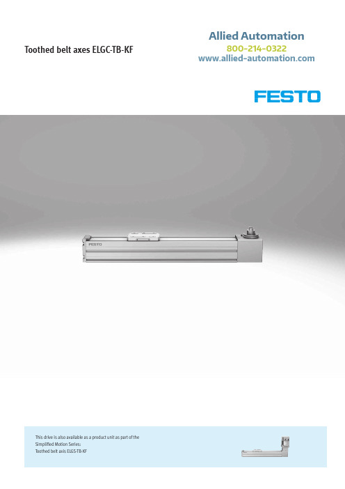
Toothed belt axes ELGC-TB-KFThis drive is also available as a product unit as part of the Simplified Motion Series:Toothed belt axis ELGS-TB-KFAllied Automation800-214-03222d Internet: /catalogue/...Subject to change – 2020/05Toothed belt axes ELGC-TB-KF, with recirculating ball bearing guideKey featuresAt a glance• Optimal installation space to working space ratio• Protected against external influences by internal guide • Compact, integrated coupling, easy to service • Unique assembly system• Compact double bearing integrated in the axis to save space • Stainless steel cover strip kept in place with magnetic strips •Easy to clean and less susceptible to contaminationCompactFlexibleIntegratedProtectedOptimum dimensions thanks to the in-tegrated compact coupling and a very short slideAdapterless combination of ELGC and EGSC using the innovative "one size down" assembly systemSimple position sensing with proximity switch SMT-8M and integrated positioning magnetThe cover strip and optional vacuum connection protect against particle emissions and atmospheric pollutionModular and flexible with motor, motor mounting kit and servo drive Motor Servo drive Motor mounting kit Servo motorServo driveAxial kitStepper motor Motor controller for stepper motorParallel kitSimplicity in one unitThis product is also available as a product unit as part of the Simplified Motion Series:• The Simplified Motion Series combines the simplicity of pneumatics with the benefits of electric automation. The perfect solution for all users who are looking for an electric alternative for very simple movement and positioning tasks, but don't want the commissioning process for traditional electric drive systems that can often be quite complex.• Simplified functionality for simple movements between two end positions • A variety of movements with different mechanical systems • Integrated products eliminate the need for a control cabinet• Quick and easy commissioning without software or special expertise • Digital I/O and IO-Link integrated as standard32020/05 – Subject to changed Internet: /catalogue/...Toothed belt axes ELGC-TB-KF, with recirculating ball bearing guideKey featuresFrom individual axis to complete handling system• The toothed belt and spindle axes ELGC and mini slide EGSC form a scalable modular system for compact automation• The shared platform architecture creates a consistent range with matching in-terfaces. A large number of systems can be realised entirely without adapter plates• Powerful drive and guide components ensure a long service life, as well as excellent load capacity and reliability• The uniform and universal range of accessories reduces warehousing and design costs• Two position sensing functions can be selected:– With magneto-resistive proximity switches (detection via integrated magnets)– With inductive proximity switches (detection via switch lug)The products for the handling system Spindle axis ELGC-BSToothed belt axis ELGC-TB Guide axis ELFC Mini slideEGSCTypical handling systemsFor applications where compact dimensions are essential, the axes ELGC can be combined into veryspace-saving handling systems that are suitable for assembly systems, test and inspection systems, small parts handling, the electronics industry and desktop applications. The very compact linear axes ELGC, mini slide EGSC and electric cylinder EPCC offer an optimal ratio between installation space and working space. They feature a common system approach and platform architecture and the connections are largely adapterless.Cantilever systemPlanar surface gantry3-dimensional gantryToothed belt axes ELGC-TB-KF, with recirculating ball bearing guideKey featuresMatrix showing combinations between axis ELGC/ELGS-TB, ELGC/ELGS-BS, mini slide EGSC/EGSS-BS, electric cylinder EPCC/EPCS-BS and guide axis ELFCMounting options with profile mounting and via angle kitWith profile mounting EAHF-L2-…-P-D…With angle kit EHAA-D-L2-…-APMatrix showing combinations between axis ELGC/ELGS-TB, ELGC/ELGS-BS, mini slide EGSC/EGSS-BS, electric cylinder EPCC/EPCS-BS and guide axis ELFC Assembly options with adapter kitWith adapter kit EHAA-D-L24d Internet: /catalogue/...Subject to change – 2020/05Toothed belt axes ELGC-TB-KF, with recirculating ball bearing guide Type codes5 2020/05 – Subject to change d Internet: /catalogue/...6d Internet: /catalogue/...Subject to change – 2020/05Toothed belt axes ELGC-TB-KF, with recirculating ball bearing guidePeripherals overview21345678910111272020/05 – Subject to changed Internet: /catalogue/...Toothed belt axes ELGC-TB-KF, with recirculating ball bearing guidePeripherals overviewSealing air connectionAir is exchanged between the interior of the cylinder and the environment via a sealing air connection. This prevents negative pressure or excess pressure arising in the interior of the cylinder.Additional functions of the connection:• Application of slight negative pressure prevents emission of particles • Application of slight excess pressure prevents atmospheric pollution Suitable push-in fittings d page 268d Internet: /catalogue/...Subject to change – 2020/05Toothed belt axes ELGC-TB-KF, with recirculating ball bearing guideData sheet-N- Size 45 … 80-T- Stroke length200 … 2000 mm -É-801)At 0.2 m/s1)Note operating range of proximity switches1)Including slide1) At max. feed force92020/05 – Subject to changed Internet: /catalogue/...Toothed belt axes ELGC-TB-KF, with recirculating ball bearing guideData sheetThe mass moment of inertia J A of the entire axis is calculated as follows:J A = J O + J H x working stroke [m] + J L x m payload [kg]HomingHoming can be carried out in two ways:• Against a fixed stop • Using a reference switchThe following values must be observed:MaterialsSectional view123456710d Internet: /catalogue/...Subject to change – 2020/05Toothed belt axes ELGC-TB-KF, with recirculating ball bearing guideData sheetCharacteristic load valuesThe indicated forces and torques refer to the centre of the guide. The point of application of force is the point where the centre of the guide and the longi-tudinal centre of the slide intersect.These values must not be exceeded during dynamic operation. Special attention must be paid to thedeceleration phase.Distance from the slide surfaceto the centre of the guideH- -NoteIf the axis is subjected to two or more of the indicated forces and torques simulta-neously, the following equation must be satisfied in addition to the indicated maximum loads:Calculating the load comparison factor:For a guide system to have a service life of 5000 km, the load comparison factor must have a value of fv š 1, based on the maximum permissible forces and torques for a service life of 5000 km.This formula can be used to calculate a guide value.The engineering software "PositioningDrives" is available for more precise calculations a F 1/M 1 = dynamic value F 2/M 2 = maximum valueffff vvvv =�FFFF yyyy 1�FFFF yyyy 2+|FFFF zzzz 1|FFFF zzzz 2+|MMMM xxxx 1|MMMM xxxx 2+�MMMM yyyy 1�MMMM yyyy 2+|MMMM zzzz 1|MMMM zzzz 2≤1Calculating the service lifeThe service life of the guide depends on the load. To be able to make a statement as to the service life of the guide, the graph below plots the load comparison factor fv against the service life.These values are only theoretical. You must consult your local Festo contact for a load comparison factor fv greater than 1.Load comparison factor f v as a function of service life lExample:A user wants to move an x kg load. Using the formula (apage 10) gives a value of 1.5 for the load comparison factor f v . According to the graph, the guidewould have a service life of approx. 1500 km. Reducing the acceleration reduces the Mz and My values. A load comparison factor f v of 1 now gives a service life of5000 km.Comparison of the characteristic load values for 5000 km with dynamic forces and torques of recirculating ball bearing guides The characteristic load values of the bearing guides are standardised to ISO and JIS using dynamic and static forces and torques. These forces and torques are based on an expected service life of the guide system of 100 km according to ISO or 50 km according to JIS.As the characteristic load values are dependent on the service life, the maximum permissible forces and torques for a 5000 km service life cannot be compared with the dynamic forces and torques of bearing guides to ISO/JIS.To make it easier to compare the guide capacity of linear axes ELGC with bearing guides, the table below lists the theoretically permissible forces and torques for a calculated service life of 100 km. This corresponds to the dynamic forces and torques to ISO.These 100 km values have been calculated mathematically and are only to be used for comparing with dynamic forces and torques to ISO. The drives must notbe loaded with these characteristic values as this could damage the axes.Feed force F as a function of input torque MELGC-TB-45ELGC-TB-60ELGC-TB-80 Second moment of areaMaximum permissible support spacing L (without profile mounting) as a function of force F In order to limit deflection in the case of large strokes, the axis may need to besupported.The following graphs can be used to determine the maximum permissible supportspacing l as a function of force F acting on the axis.The deflection is f = 0.5 mm.Force F ySize 45Size 60/80Force F zSize 45Size 60/80ELGC-TB-45ELGC-TB-60ELGC-TB-80Recommended deflection limitsAdherence to the following deflection limits is recommended so as not to impairthe functionality of the axes. Greater deformation can result in increased friction,greater wear and reduced service life.1) Includes a stroke reserve of approx. 3 mm1) Recommended screw-in depth1) Recommended screw-in depth-NoteH-Depending on the combination of motor and drive, it may not be possible to reach the maximum feed force of the drive.1) The input torque must not exceed the max. permissible transferable torque of the axial kit.Profile mounting EAHF-L2-…-P-SFor mounting the axis on the side of the profile•Material:Anodised wrought aluminium alloyRoHS-compliantToothed belt axes ELGC-TB-KF, with recirculating ball bearing guide AccessoriesProfile mounting EAHF-L2-…-P Material:Anodised wrought aluminium alloy RoHS-compliant • For mounting the axis on the side of the profile.The profile mounting can be attached to the mounting surface using the drillhole in the centre.21 2020/05 – Subject to change d Internet: /catalogue/...Toothed belt axes ELGC-TB-KF, with recirculating ball bearing guide AccessoriesProfile mounting EAHF-L2-…-P-D… Material:Anodised wrought aluminium alloy RoHS-compliant • For axis/axis mounting without adapter plate• Mounting option: base axis with one-size-down assembly axis (apage 4)22d Internet: /catalogue/...Subject to change – 2020/05Toothed belt axes ELGC-TB-KF, with recirculating ball bearing guide AccessoriesAdapter kit EHAA-D-L2 Material:Anodised wrought aluminium alloy RoHS-compliant • For axis/axis mounting with adapter plate• Mounting option: base axis with same size or one-size-down assembly axis (a page 4)• When motors are mounted using parallel kits, this may lead to interfering contours. In this case, the adapter plate is required for height compensation (download CAD data a)23 2020/05 – Subject to change d Internet: /catalogue/...Toothed belt axes ELGC-TB-KF, with recirculating ball bearing guide AccessoriesAngle kit EHAA-D-L2-…-AP Material:Anodised wrought aluminium alloy RoHS-compliant • For mounting one-size-down vertical axes (assembly axes) on base axes with mounting position "slide at top"(apage 4)24d Internet: /catalogue/...Subject to change – 2020/05Toothed belt axes ELGC-TB-KF, with recirculating ball bearing guide AccessoriesSwitch lug EAPM-L2-SLSFor sensing using inductive proximity switches SIES-8M Material: Galvanised steelRoHS-compliantSensor bracket EAPM-L2-SH Material:Anodised wrought aluminium alloyRoHS-compliant25 2020/05 – Subject to change d Internet: /catalogue/...Toothed belt axes ELGC-TB-KF, with recirculating ball bearing guideAccessories1) Packaging unit26d Internet: /catalogue/...Subject to change – 2020/05Festo - Your Partner in AutomationConnect with us/socialmedia1Festo Inc.2Festo Pneumatic 3Festo Corporation 4Regional Service Center 5300 Explorer DriveMississauga, ON L4W 5G4CanadaAv. Ceylán 3,Col. Tequesquináhuac 54020 Tlalnepantla, Estado de México1377 Motor Parkway Suite 310Islandia, NY 117497777 Columbia Road Mason, OH 45040Festo Customer Interaction CenterTel:187****3786Fax:187****3786Email:*****************************Multinational Contact Center 01 800 337 8669***********************Festo Customer Interaction Center180****3786180****3786*****************************S u b j e c t t o c h a n g eAllied Automation800-214-0322。
施耐德电气 32000 系列微型电磁阀 使用说明书

21
manual valves
1
Cv = 1.3
Valves Mod. 434-910TF and 434-915TF
Cv = 1.3
Mod. 434-910TF Actuation Force at 87 psi = 2.25 lbf Mod. 434-915TF Actuation Force at 87 psi = 8.3 lbf
PNEUMATIC DATA
Operating pressure
0 - 10 bar, (0 - 145 psi); (Down to -9 bar vacuum; 28" Hg with Series 4
Nominal pressure
6 bar, (87 psi)
Nominal flow (QN)
Mod. 134 - 935TF
Mod. 134-900TF
Mod. 154 - 900TF
Mod. 434 - 910TF Mod. 434 - 915TF
Mod. 454 - 910TF Mod. 454 - 915TF
Mod. 434 - 900TF Mod. 434 - 905TF
Mod. 454 - 900TF Mod. 454 - 905TF
Cv = 1.3
1
Series 1 and 4
Cv = 1.3
1/4" Ported Manually Operated Valves
3-way/2-position, 5-way/2-position and 5-way/3-position Ports 1/4” NPTF
manual valves
ports 4 = 1/4”
TP系列-思多奇中国

!
不要在回路中液压油温度高于 80℃(176oF)的情形下对接 - 拆断;
• 为了安全,不要在公母两侧同时带有残存压力的情形下对接;
• 快速接头不对接时,建议使用保护帽(VR 系列可以提供塑料帽或铝帽);保护帽的使用能减少油路的污染,避免对
内部阀体的损坏。
• 检查要使用的快速接头的接口的最大允许工作压力(L 或 S 系列 DIN2353/ISO8434-1 等)。
性能
型号
规格
ISO 标准流量
STUCCHI 建议最大流量
对接力矩 *
拆断力矩 *
泄漏量 **
型号
对接状态
最大工作压力 公接头
母接头
对接状态
爆破压力 公接头
母接头
* 对接力矩和拆断力矩是没有残存压力时的数据;残存压力增加时,力矩会随之增加。 ** 泄漏量数值是指没有残存压力时每次对接 - 拆断的液压油损失的理论数据; • 温度范围 - 标准密封 NBR( 丁腈橡胶 ):-20℃到 100℃ (-4oF 到 212oF) • 通过测试: 此系列快速接头按照 ISO7241-2 测试方法,通过了最大工作压力 20 万次的脉冲测试。
材质为高强度碳钢, 表面镀锌
解决方案层现叠出
VR 系列
使用方法
• 对接前清洁对接部位 , 避免污染物进入液压回路。 • 公接头插入母接头 , 旋转护套直至终点。 • 拆断时从母接头上彻底旋松螺纹护套。
警示
• 选择和使用产品时,请仔细阅读我们产品总目录的通用介绍; • 在残存压力下,不要将断开状态下的公接头或者母接头当做堵头使用。 • 不要在回路中有液压油流动和 / 或有动态压力的情形下对接 - 拆断;
VR 系列
互换性标准 : 与同类型快速接头互换 (RK 系列 )
TORUS 3D 槽罐清洗头 产品使用说明书
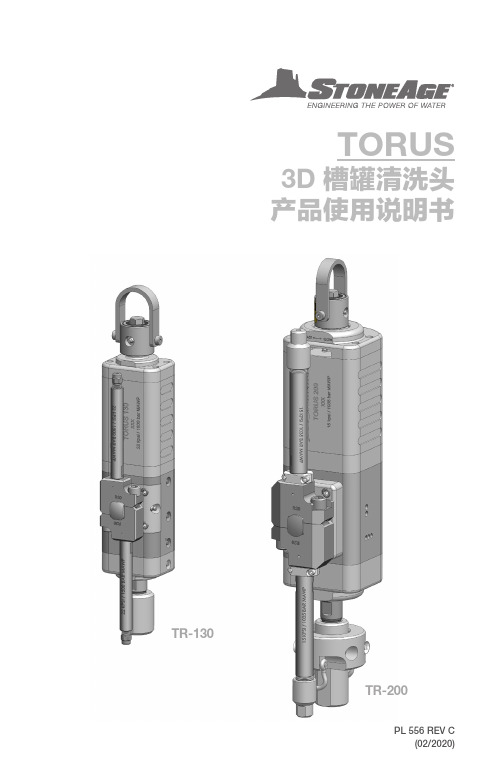
TORUS3D 槽罐清洗头产品使用说明书PL 556 REV C(02/2020)TR-130TR-2003各型号产品明细 (3)各型号产品主要特点 (3)45产品说明与用途 (5)设备运行 - 选择流量模块与喷嘴 (6)设备运行 - 入口连接接头与速度调整 (7)TORUS TR-130 配件 (8)设备维护 (9)设备维护资源信息 (10)设备维护 - TR-130 组件 (11)设备维护 - TR130 240-RXX-X 流量模块组件 (12)设备维护 - TR130 170 十字轴芯组件 (12)设备维护 - TR130 120 入口连接组件 (13)设备维护 - TR130 130 转向组件 (13)设备维护 - TR130 200 制动组件 (14)设备维护 - TR130 226 齿轮组件 (14)设备维护 - TR-130 更换高压密封 (15)安装紧固件 (16)18产品说明与用途 (18)设备运行 - 选择流量模块与喷嘴 (19)设备运行 - 入口连接接头与速度调整 (20)设备维护 (21)设备维护资源信息 (22)设备维护 - TR-200 组件 (23)设备维护 - TR200 240-RXX-X 流量模块组件 (24)设备维护 - TR200 170 十字轴芯组件 (24)设备维护 - TR200 120 入口连接组件 (25)设备维护 - TR200 130 转向组件 (25)设备维护 - TR200 200 制动组件 (26)设备维护 - TR200 226 齿轮组件 (26)设备维护 - TR-200 更换高压密封 (27)安装紧固件 (28)3223866-795-1586 • StoneAge Inc.466 S. Skylane DriveDurango, CO 81303, USA Phone: 970-259-2869Toll Free: StoneAge NL Reedijk 7Q3274 KE Heinenoord Netherlands(+31) (0) 85 902 73 70**************************产品特点:•互换型接头和流量模块 - 一个清洗头可适用于多种压力与流量等级,性价比高。
DixonQuickCoupling2012狄克逊快速接头2012
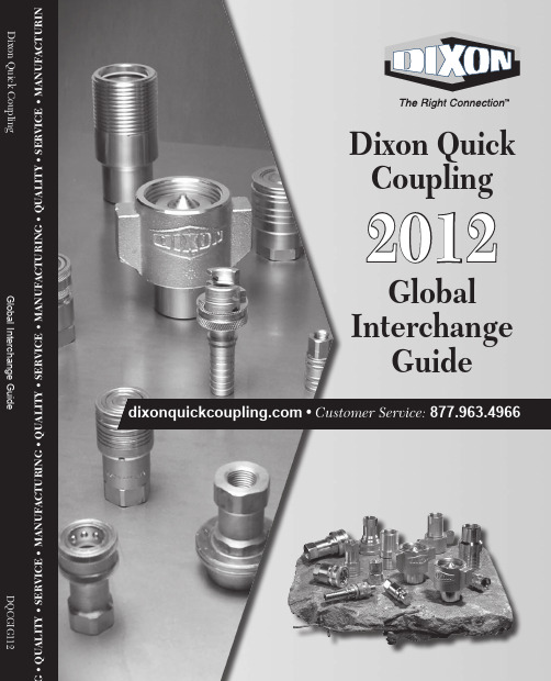
• 2012Global Interchange GuideDixon Quick Coupling • Q U A L I T Y • S E R V I C E • M A N U F A C T U R I N G • Q U A L I T Y • S E R V I C E • M A N U F A C T U R I N G • Q U A L I T Y • S E R V I C E • M A N U F A C T U R I N • Customer Service:Dixon Quick CouplingWarning!1877.963.4966 • DF SeriesJ SeriesM SeriesL SeriesNK SeriesBR SeriesA SeriesCJ SeriesSHD Series2877.963.4966 • AG SeriesK SeriesTR Series3877.963.4966 • HT8 (1")HT6 (3/4")HT5 (5/8")HT4 (1/2")HT3 (3/8")HT2 (1/4")HT SeriesH SeriesLarge H SeriesV SeriesLarge V SeriesV16 (2")V12 (1-1/2")V10 (1-1/4") W Series W12 (1-1/2")W10 (1-1/4")W8 (1")W6 (3/4")4877.963.4966 • 5877.963.4966 • ST6 (3/4")ST8 (1")ST4 (1/2")ST3 (3/8")ST2 (1/4")ST SeriesTest PointPD SeriesT SeriesLarge ST SeriesST16 (2")ST8-V2 (1")6877.963.4966 • E Series1/2"EA SeriesCM SeriesLarge E SeriesE16 (2")E12 (1-1/2")E10 (1-1/4")877.963.4966 • 78877.963.4966 • J SeriesK SeriesPD SeriesSHD SeriesT SeriesW SeriesA Dixon Quick Coupling representative is ready to assist you at 800.827.0770This directory is provided to assist in the identification of competitive couplings. While we have made every effort to ensure the accuracy of the data, competitors may change their part numbers, specifications, orinterchange without notice. Therefore, you should not rely solely on this guide as the basis for interchange. Please refer to the page shown to ensure that the interchange is correct.AttentionRequired!Competitor Number Dixon QuickCoupling Number Competitor'sName DQC112 Page #0C J2M1Parker 240E J3M2Parker 240F J4M3Parker 2401-421000-SS 25 FS 2EF2-S APW 13501-421010-SS 25 MS 2EM2-S APW 13701-421100-SS 25 FP E2F2-S APW 13601-421110-SS 25 MP E2M2-S APW 13801-421110-SS 38 FS 3EF3-S APW 13501-421200-SS 38 MS 3EM3-S APW 13701-421300-SS 38 FP E3F3-S APW 13601-421310-SS 38 MP E3M3-SAPW 13802CCBAN 1BRF1-B-7Battlefield 5302CCBBN 1BRM1-B-7Battlefield 5402CCDAN 1BRF2-B-7Battlefield 5302CCDBN 1BRM2-B-7Battlefield 5402CKBAN BR1F1-B-E-7Battlefield 5302CKBBN BR1M1-B-E-7Battlefield 5402CKDAN BR1F2-B-E-7Battlefield 5302CKDBN BR1M2-B-E-7Battlefield 5404DVBAH D2F1Battlefield 1404DVBBH D2M1Battlefield 1704DVBBN D2M1-B Battlefield 1704DVBBR D2M1-S Battlefield 1704DVDAH D2F2Battlefield 1404DVDAN D2F2-B Battlefield 1404DVDAR D2F2-S Battlefield 1404DVDBH D2M2Battlefield 1704DVDBN D2M2-B Battlefield 1704DVDBR D2M2-S Battlefield 1704DVDCH D2S2Battlefield 1904DVDCN D2S2-B Battlefield 1904DVDCR D2S2-S Battlefield 1904DVDDH D2B2Battlefield 2004DVDDH D2B2-B Battlefield 2004DVECH D2S2.5Battlefield 1904DVFAH D2F3Battlefield 1404DVFAN D2F3-B Battlefield 1404DVFAR D2F3-S Battlefield 1404DVFBH D2M3Battlefield 1704DVFBN D2M3-B Battlefield 1704DVFBR D2M3-S Battlefield 1704DVFCH D2S3Battlefield 1904DVFCN D2S3-B Battlefield 1904DVFCR D2S3-S Battlefield 1904DVFDH D2B3Battlefield 2004DVXIH D2E2Battlefield 2004DVY1H D2H2Battlefield 2004ECDAN 2UF2-B Battlefield 4004ECDBN 2UM2-B Battlefield 4004ECDCN 2US2-B Battlefield 4004ECDDN 2UB2-B Battlefield 4004ECFAN 2UF3-B Battlefield 4004ECFBN 2UM3-B Battlefield 4004ECFCN 2US3-B Battlefield 4004ECFDN 2UB3-BBattlefield40Competitor Number Dixon Quick Coupling Number Competitor'sName DQC112 Page #04EVDAH CJ2F2-LG Battlefield 3204EVDAN CJ2F2-B Battlefield 3204EVDBH CJ2M2-LG Battlefield 3304EVDBN CJ2M2-B Battlefield 3304EVFAH CJ2F3-LG Battlefield 3204EVFAN CJ2F3-B Battlefield 3204EVFBH CJ2M3-LG Battlefield 3304EVFBN CJ2M3-B Battlefield 3304FVBBH M2M1Battlefield 2904FVDAH M2F2Battlefield 2804FVDBH M2M2Battlefield 2904FVDBN M2M2-B Battlefield 2904FVFAH M2F3Battlefield 2804FVFBH M2M3Battlefield 2904FVSAN M2F2-B Battlefield 2804LKDAH L2F2Battlefield 3704TKBAH J2F1Battlefield 2304TKBBH J2M1Battlefield 2404TKDAH J2F2Battlefield 2304TKDAN J2F2-B Battlefield 2304TKDBH J2M2Battlefield 2404TKDBN J2M2-B Battlefield 2404TKDCH J2S2Battlefield 2504TKDDH J2B2Battlefield 2604TKFAH J2F3Battlefield 2304TKFBH J2M3Battlefield 2404TKFCH J2S3Battlefield 2504TKFDH J2B3Battlefield 2606JCFAN 3UF3-B Battlefield 4006JCFBN 3UM3-B Battlefield 4006JCFCN 3US3-B Battlefield 4006JVFAH CJ3F3Battlefield 3206JVFAN CJ3F3-B Battlefield 3206JVFBH CJ3M3Battlefield 3306JVFBN CJ3M3-B Battlefield 3306JVGAH CJ3F4Battlefield 3206JVGAN CJ3F4-B Battlefield 3206JVGBH CJ3M4Battlefield 3306JVGBN CJ3M4-B Battlefield 3306KVDAH D3F2Battlefield 1406KVDBH D3M2Battlefield 1706KVDDH D3B2Battlefield 2006KVFAH D3F3Battlefield 1406KVFAN D3F3-B Battlefield 1406KVFAR D3F3-S Battlefield 1406KVFBH D3M3Battlefield 1706KVFBN D3M3-B Battlefield 1706KVFBR D3M3-S Battlefield 1706KVFCH D3S3Battlefield 1906KVFCN D3S3-B Battlefield 1906KVFCR D3S3-S Battlefield 1906KVFDH D3B3Battlefield 2006KVGAH D3F4Battlefield 1406KVGBH D3M4Battlefield 1706KVGCH D3S4Battlefield19。
FESTO VEAB比例压力调节器安装说明书

1About this document 1.1Applicable documents1.2Product Labelling–Observe the specifications on the product.Warning SymbolThe following warning symbol can be seen on the product:2Safety2.1Safety instructions–Only use the product in original status without unauthorised modifications.–Only use the product if it is in a perfect technical condition and it is not damaged in any way.–Take into consideration the ambient conditions at the location of use.–Before working on the product, switch off the power supply and secure it against being switched on again.–When installing the product, ensure that it can only be accessed by authorised persons.–Observe additional safety instructions in chapter è Installation.2.2Intended useThe product is intended to regulate the pressure in proportion to a specified setpoint value.The product is intended for use in industrial environments.2.3Training of qualified personnelWork on the product may only be carried out by qualified personnel who can evaluate the work and detect dangers. The qualified personnel have skills and experience in dealing with electropneumatic (open-loop) control technology.3Additional information–Contact the regional Festo contact if you have technical problems è .–Accessories and spare parts è /catalogue.4Product overview4.1Functional principleA built-in pressure sensor records the pressure at the working port and compares this value with the setpoint value. In the event of deviations between the setpoint value and actual value, the valve regulates until the outlet pressure has reached the setpoint value.4.2Structure4.2.1Product design In-line valveFig. 2:View from frontLEDElectrical connection, M8 plug Working air port (2)Fig. 3:View from rear Compressed air port (1)Exhaust air port (3)Through-holes (3x) for mounting the valveSub-base valveFig. 4:View from frontLEDElectrical connection, M8 plug Through-holes (2x) for mounting the valve on the sub-baseFig. 5:View from beneathWorking air port (2)Exhaust air port (3)Compressed air port (1)4.2.2Product variants5Transport and storage–Store the product in a dry, UV- and corrosion-protected environment.–Ensure short storage times.6Mechanical installation1.Make sure there is sufficient space for the connecting cable and tubing con-nections.ÄIn this way you will prevent the connecting lines and the tubes fromkinking.2.Place the valve as close to the consumer as possible.ÄThis leads to improved control precision and shorter response times.Mounting options of the valve:–Through-hold mounting of the in-line valve through 3 lateral through-holes–Mounting of the in-line valve to H-rails using H-rail mounting VAME-P7-T è 1.1Applicable documents–Mounting of the in-line valve to the mounting plate VAME-P7-Y è 1.1 Appli-cable documents–Mounting of the sub-base valve using 2 through holes using the sub-baseVABM-.... è 1.1 Applicable documents7Installation7.1Pneumatic installation (in-line valve)Valves for standard operation (overpressure)1.Attach the tubing to the following connections:–Compressed air port (1)–Working air port (2)2.Fit a silencer at the exhaust port (3) or provide for ducted exhaust air .Valves for vacuum operation (reversible operation)1.Attach the tubing to the following connections:–Vacuum port (3)–Working air port (2)2.Mount silencer on the compressed air port (1) to protect the valve fromcoarse dirt particles.Operating medium7.2Electrical installation1.If a screened cable is used: earth the shield at the cable end away from thevalve.2.Install electrical connecting cable without squeezing, kinking or stretching.3.Screw electrical connecting cable onto the M8 plug connector. Tighteningtorque: maximum 0.3 NmTab. 4:Pin allocation for M8 plug, 4-pin8Commissioning1.Check the operating conditions and limit values è Technical data.2.Switch on compressed air supply.3.Check pneumatic connection points for tightness.4.Connect valve to a setpoint signal.5.Switch on operating voltage.9Cleaning1.Switch off the following energy sources to clean the outside:–Compressed air–Operating voltage2.Clean the outside of the product with a soft cloth. Do not use aggressivecleaning agents.10Malfunctions10.1Diagnostics10.2Fault clearance11Dismounting1.Switch off setpoint voltage.2.Switch off operating voltage.3.Switch off compressed air supply.4.Remove electrical connecting cables.5.Remove compressed air lines.6.Dismantle the product.12Technical datacommercial and residential/mixed-use areas, it may be necessary to take measures to suppress radio interference.Tab. 7:General technical data the ideal characteristic curve.Tab. 8:Control characteristics。
巴什卡样本 液压联轴器
07
液压联轴器系列
蛇形弹簧联轴器三大技术优势
蛇形弹簧联轴器三大技术优势
◆ 铝壳采用特殊铝合金,根据客户需求可做热处理,强度提高2-3倍。 ◆ 弹簧采用优质弹簧钢,1140以上单片弧形弹簧压平后可恢复原有形状。 ◆ 齿形由四轴联动数控加工中心加工而成,可保证齿形的特殊弧面及精度。
无外露轴伸,轴伸不生锈 有防水结构,润滑效果好
维护时只需径向调节,无需轴向空间
冷装:安装时力矩扳手拧紧多个螺栓, 拧紧胀套时半联轴器有轴向窜动 胀套锥面尾部存在应力集中
胀套胀紧配合面短,刚性差,承受弯矩小
需要专用拆卸螺钉,费时费力 有外露轴伸,轴伸易生锈 无防水结构,润滑效果差
维护时轴向调节螺丝,需要较大轴向空间
mm
210 252 272 310 348 386 454 510 567 632 680 756 848 872 957 1048 1143
Do
间隙 C
mm
123.8 142.1 160.3 179.4 217.5 254.0 269.2 304.8 355.0 394.0 437.0 497.8 533.4 571.5 609.6 647.7 711.2
额定 转矩 Tn N.m
3730 6280 9320 13700 19900 28600 39800 55900 74600 103000 137000 186000 249000 336000 435000 559000 746000
许用 转速
n rpm
3600 2440 2250 2025 1800 1650 1500 1350 1225 1100 1050 900 820 730 680 630 580
费斯托(Festo)螺纹阀门说明书
Translation of the original instructions 1Identification EXTab. 1 2Further applicable documentsTechnical data for the product can have different values in other documents. For operation in an explosive atmosphere, the technical data in this document always have priority.All available documents for the product è /pk.3Safety 3.1Intended useThe solenoid valve is intended for controlling pneumatic actuators.3.2General safety instructions–The device can be used under the stated operating conditions in zones 1 and2, explosive gas atmospheres, and in zones 21 and 22, explosive dust atmospheres.–Carry out all work outside potentially explosive areas.–Observe the operating instructions for the solenoid coil.–Installation and commissioning should only be conducted by qualified personnel.–Only use media in accordance with the specifications è 10 Technical data.4FunctionBy means of external electric switching, the valve pressurises the downstreamcompressed air flows alternately or simultaneously. The bistable valve isrerouted through reciprocal switching on of the voltage to the solenoid coils and maintains the switching position up to the countersignal even after the signal is removed.5ApplicationThe explosion protection category of the entire system is dependent on the category of the combination of the solenoid valve and the solenoid coil.6Commissioning The discharge of electrostatically charged parts can lead to ignitable sparks.•Prevent electrostatic discharge through the use of appropriate installationand cleaning measures.•Include the device in the system’s potential equalisation.Related type of ignition protection: c (constructional safety)Strong chargegenerating processes can charge nonconductive layers and coatings on metal surfaces.Particulate matter in the compressed air can cause electrostatic charges.Escaping exhaust air can swirl up dust and create an explosive dust atmosphere.–For battery/block mounting, mount the valves to the manifold rails or manifold blocks intended for it.The solenoid coil is mounted on the electrically actuated valves using the supplied spring washer and knurled nut.–Push the solenoid coil and spring washer over the armature guide tube, tighten the knurled nut. Tightening torque: 1 … 1.5 NmImpact movements involving rust and light metals and their alloys can result in the formation of sparks.•No not use any tools with corroded surfaces.•Protect the product from falling objects.–Limit the number and dimensions of disassembled connections to a minimum and use short tubing.–Ensure that no mechanical stresses can occur.–Seal unused openings with blanking plugs or slot covers.–Ensure that surfaces to be cleaned can be easily accessed.7Operation–Draw in operating medium outside potentially explosive areas.–Do not operate the device with separate pilot air. Do not turn coding.–Do not use LR intermediate pressure regulator plates in potentially explosive areas. The vented air can stir up dust.8MalfunctionsMalfunctionRemedyAudible leakage at the connections Check fittings of the connections.Incomplete ventilation of an output Ensure constant pressure in the system.Switching failuresConsiderably slower switching timesCheck switching function of the valve for fluctuations in current, signal errors or delays.Protect against penetration of foreign matter.Replace device.Tab. 29Service and care–Only clean the device with a damp cloth.–Service device after 5 million cycles or not later than after 6 months.The replacement of wearing and spare parts is possible in individual cases.Repairs of this type must only be carried out by trained and authorised specialists.–Please contact your Festo technical consultant.10Technical data8086862(J)M...FH-...-EXSolenoid valve Tiger Classic8086862201805b [8086864]Festo SE & Co. KG Ruiter Straße 82 73734 Esslingen Germany+49 711 347Tab. 311Solenoid coils for entire systemVoltage Type Part number Identification markVACFBK111EX4M8059804VACFBK115EX4M8059805VACFBK1110EX4M8059806 24 V DCVACFBK1120EX4M8059807 24 V AC VACFBK11A1EX4M8059808VACFBK13A1EX4M8059809 230 V ACVACFBK13A5EX4M8059810VACFBK116B1EX4M8059811 110 V ACVACFBK116B5EX4M8059812Ex II 2GD (zones 1, 21)24 V DC MSFG24EX536931 24 V AC MSFW2450/60EX536932 110 V AC MSFW11050/60EX536933 230 V AC MSFW23050/60EX536934Ex II 3GD1) (zones 2, 22)1) Use the related plug socket MSSDFM16. Tab. 4。
TOX冲压技术
TOX® PRESSOTECHNIK
14
1.1 TOX ® 气液增力式冲压技术
1.1.4 国际汽车制造业冲压技术发展态势: 中小吨位的冲压设备普遍采用气液增力缸 驱动,取代了传统的机械冲床和油压机
TOX® PRESSOTECHNIK
15
1.2 TOX ® 电子冲压技术
1.2.1 原理
侍服电机驱动,滚珠丝杆传递并输出冲压力。
1.1.3 先进的技术性能 ● 可自由编程控制的气液增力缸
可自由编程控制的托克斯气液增力缸是一个 高灵敏度的带有位移及压力传感器的闭环伺 服驱动系统。它的极佳的动态特性用于加工 复杂几何形状,要比传统的驱动系统快 30%左右.
优势:
• • • • 可自由编程控制执行位移-时间关系 可自由编程控制执行冲压力-时间关系 可自由编程控制执行冲压力-位移关系 通过冲压力、位移和时间的测量控制 可进行加工质量在线实时自动检测 • • 可进行加工全过程自动监控 可采集、存储、处理及输出实测数据
TOX® PRESSOTECHNIK
双支承工作活塞,工作更为
集成化设计,仅需一个4/2或5/2气动 主控阀即可完成全部组合动作控制。
8
1.1 TOX ® 气液增力式冲压技术
1.1.2 特点: B. 独特的运动特性 ——TOX® 专利的三行程冲压循环
TOX® 气液增力缸工作全过程演示
1) 快进行程 由前部的快进气缸驱动, 使模具到位与工件接触。
在建办事处:湖南省(长沙市)、江西省
TOX® PRESSOTECHNIK
5
1. TOX ® 冲压技术
TOX ® 电子驱动力模块 TOX ® 气液增力缸
TOX ® 气液增力式冲压技术及设备
TOX® PRESSOTECHNIK
DS3-S111N-D24K1
DS3-S1/11N-D24K1宁波思承在欧美那边有自己的合资采购公司,直接国外工厂拿货,为您省去中间环节,给您节省时间和金钱,现公司与几个大的主机厂合作。
DUPLOMATIC泵和阀部分有备现货,欢迎来公司考察后合作!液压阀是一种用压力油操作的自动化元件,它受配压阀压力油的控制,通常与电磁配压阀组合使用,可用于远距离控制水电站油、气、水管路系统的通断。
用于降低并稳定系统中某一支路的油液压力,常用于夹紧、控制、润滑等油路。
有直动型、先导型、叠加型之分.液压传动中用来控制液体压力﹑流量和方向的元件。
其中控制压力的称为压力控制阀,控制流量的称为流量控制阀,控制通﹑断和流向的称为方向控制阀。
按功能分类:流量阀(节流阀、调速阀,分流集流阀)、压力阀(溢流阀,减压阀,顺序阀,卸荷阀)、方向阀(电磁换向阀、手动换向阀、单向阀、液控单向阀)按安装方式分:板式阀,管式阀,叠加阀,螺纹插装阀,盖板阀意大利迪普马集团实力雄厚,技艺精良,产品种类齐全,技术支持完备。
其麾下液压公司开发的液压泵系列产品和液压控制阀系列产品不但严格满足国际标准(ISO4401、DIN、SAE等),更加受JUN工领域的信任与青睐。
其极限温度产品,更是在液压领域广泛赢得美誉。
Duplomatic是一个意大利品牌,于1952成立。
技术创新、客户至上是Duplomatic的政策,这些都是在Duplomatic公司立足于液压行业的战略要点。
如今,公司为了强化其贸易、技术和生产,重新调整了公司管理结构。
2008年公司营业额已超过3100万欧元。
DS3-S1/11N-D24K1该阀具有三通阀和四通阀两种形式,具有油口排列不同的可互换阀芯。
该阀可采用直流式或交流电磁铁,直流电磁铁也可采用交流供电,但需使用带桥式整流器的插头。
迪普马DUPLOMATIC液压泵、液压阀常见备货系列:迪普马DUPLOMATIC泵: 外啮合齿轮泵、液压泵、齿轮泵、柱塞泵、叶片泵迪普马DUPLOMATIC压力控制阀:先导式溢流阀、先导式溢流阀、压力控制阀、电磁溢流阀、溢流阀、压力控制阀。