石墨烯文献汇总(nature and science)
石墨烯
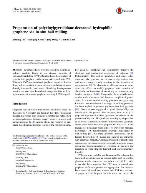
Preparation of polyvinylpyrrolidone-decorated hydrophilic graphene via in situ ball millingJuxiang Lin 1•Danqing Chen 1•Jing Dong 1•Guohua Chen 1Received:9June 2015/Accepted:20August 2015/Published online:1September 2015ÓSpringer Science+Business Media New York 2015Abstract Graphene sheets were processed by in situ ball-milling graphite flakes in an ethanol solution of polyvinylpyrrolidone (PVP).Results showed exfoliation of graphite into graphene,with surfaces decorated with PVP.This new PVP-functionalized graphene could be further dispersed in varieties of polar solvents,including ethanol,dimethylformamide,and water.Resulting homogeneous solution has more than 4months of storage stability,with the highest concentration of graphene reaching 1.7300mg/ml.IntroductionGraphene has attracted tremendous attentions since its discovery by Novoselov and Geim in 2004[1].This unique material has found uses in many technological fields,such as nanoelectronics,devices,energy storage,sensors,and nanocomposites [2–4].Among them,the research in gra-phene-based nanocomposites is one of the most promising.For example,graphene can significantly improve the electrical and mechanical properties of polymer [5].Unfortunately,like carbon nanotubes and many other nanomaterials,graphene sheets have a high surface area and surface energy,easily resulting in the formation of agglomerates [6].To eliminate or alleviate such an issue,there are efforts to modify graphene with varieties of chemicals,by formation of covalently or non-covalently bonded surfaces [7–10].Frequently,these modifications require toxic chemicals and involve complicated proce-dures.As a result,neither are they green nor energy saving.Recently,mechanochemical strategy of milling processes has been applied to generate graphene from bulk graphite [11].Some reports suggested a good dispersibility can benefit after the process.For instance,Jeon et al.[12]prepared edge-functionalized graphene nanosheets in the presence of dry ice.The products were highly dispersable in solvents.Similarly,hydroxyl-functionalized graphene sheets were exfoliated from graphite by Yan et al.in the presence of potassium hydroxide [13].Our group prepared polystyrene (PS)-functionalized graphene nanosheets by ball milling [14].Resulting graphene nanosheets can be further dispersed in PS matrix and showed an extraordi-nary electrical pared with other modification approaches,mechanochemical approach integrates prepa-ration and functionalization of graphene in one-step and therefore is both straight forward and environmentally friendly.PVP,as a water-soluble and biocompatible polymer,has been used as a dispersant in various fields such as textiles,pharmaceuticals,cosmetics,and adhesives [15].Recently,it has also been reported that PVP can be coated onto graphene surfaces to prevent the aggregation.For instance,Bourlinos et ed sonication to coat PVP over surfaces of graphene [16].Inspired by this work,we extend theElectronic supplementary material The online version of this article (doi:10.1007/s10853-015-9373-6)contains supplementary material,which is available to authorized users.&Guohua Chenhdcgh@Juxiang Lin1300507013@ Danqing Chenchendan@ Jing Dongdongtian927@1Department of Polymer Science &Engineering,Huaqiao University,Xiamen 361021,People’s Republic ofChinaJ Mater Sci (2015)50:8057–8063DOI 10.1007/s10853-015-9373-6surface treatment strategy with ball-milling graphite inside a solution of PVP.We found the resulting hydrophilic graphene can be easily dispersed in polar organic solvents and water at high concentrations.Experimental sectionMaterialsGraphite powder(8000mesh)was placed in a desiccator prior to use.Anhydrous ethanol,N,N-dimethylformamide were purchased from Guangdong Xilong Chemical Reagent Co.,Ltd.Polyvinylpyrrolidone(PVP)was obtained from Sinopharm Chemical Reagent Co.,Ltd, China.Other raw materials were used as received.Experimental set-upThe ball milling was carried out in a vertically stirred mill, with details shown in Fig.A1(supplementary data1). Rotational speed of the stirrer was adjusted continuously from90to1300rpm.Wear-resistant zirconia milling beads,with diameters of0.5–5mm,were used as grinding media.Preparation of polyvinylpyrrolidone-decorated hydrophilic graphene sheets(PVP-GS)Graphiteflakes(1.0g)and PVP(0.005g)were weighted and premixed in a stirring ball mill(Fig.1a).Then40ml ethanol(EtOH)was added and the mixture was subjected to a continuous ball milling at90rpm for up to48h (zirconia milling beads,200g)(Fig.1b).Final mixture was dispersed in ethanol(100ml)andfiltered through a 0.22-l m PTFE membrane,followed by rinsing with water at least5times(Fig.1c)and then dried in a vacuum oven at80°C for further use.CharacterizationSamples were characterized by Scanning Electron Micro-scopy(SEM),High-resolution Transmission Electron Microscopy(HRTEM),X-ray diffraction(XRD),and Raman spectroscopy.SEM was taken on a JSM-6700F field-emitting scanning electron microscope with an oper-ating voltage of5kV.The distance between the sample and detector was7.5mm.High-resolution transmission electron microscopy(HRTEM)images were taken with H-7650(HITACHI)to determine the layers of the graphene sheets.X-ray diffraction(XRD)patterns were recorded with a D8-Advance instrument(Bruker AXS)using Cu Ka radiation generated at a voltage of40kV and a current of 40mA.The range of2h was from5°to40°with a scan-ning rate of5°per minute.Raman spectroscopy was taken with a He–Ne laser(532nm)as the excitation source (Super LabRam II system).Fourier transform infrared(FT-IR)spectroscopy of GS and PVP-GS were recorded with a Nicolet6700spectrometer(Thermo Scientific,USA)over the wavenumber of4000–400cm-1.Thermogravimetric analysis(TGA)was carried out with DTG-60H(Shimadzu) with a heating rate of10°C per minute under steadyflow of nitrogen(50ml/min).Ultraviolet–Visible(UV–Vis) spectroscopy of the graphene dispersion in water was carried out using a UV-1600spectrophotometer(Beijing Rayleigh Analytical Instruments).X-ray photoelectron spectroscopy(XPS)analysis of the samples was performed on a VG ESCALAB MK II spectrometer(VG Scientific Ltd.).Results and discussionFigure2shows the microscopic view of pristine graphite and PVP-GS.Clearly,ball milling has allowed us to receive few-layer GS from pristine graphite.It is possible that,under the help of a continuous shearing,the Vander Fig.1Schematic illustration for the preparation of PVP-graphenesheets(PVP-GS):a the graphiteflakes mixed with PVP;b PVP-GSwere prepared by shear forces from rotating balls;c PVP-GS wereindividually dispersed in water and unreacted PVP was completelyremoved byfiltrationWaals forces in the direction perpendicular to graphite surfaces were overcame,leading to the peeling of graphite sheets into GS.In contrast to those rigid and thick graphite sheets(Fig.2a),edges and surfaces of GS seem to be curly and coarse(Fig.2b),suggesting a rather thin thickness. Moreover,large pieces of graphiteflakes were crushed into small grains of about several hundred nanometers for GS. HRTEM in Fig.2c,d further revealed these thin sheets were composed of single or few-layer(B5layers)gra-pheneflakes(Fig.2d).Furthermore,X-ray diffraction(XRD)and Raman spectroscopy were used to identify defects and the crystal structure of PVP-GS.As can be seen from Fig.3a,the 8000mesh graphite has a strong sharp diffraction peak at2h angle of24.7°,indicating a highly crystalline struc-ture[17].Diffraction peak of PVP-GS,on the other hand,is weak and broad.This large difference suggests that the degree of disorder in nano-graphite crystal sheet is increased after the ball-milling process.Such a phe-nomenon can be taken as an evidence for an efficient exfoliation of graphite into graphene.Figure3b displays the Raman spectra of graphite pow-der and PVP-GS.The G band at about1580cm-1and the D band at about1350cm-1are attributed to the sp2-hy-bridized carbon bonds and the edges/defects in the gra-phene lattice,respectively.As PVP itself does not exhibit any Raman bands,PVP-GS shows a little stronger D band compared with the graphite powder,indicating the pres-ence of an edge and/or basal defect induced by exfoliation [18].It is well known that the intensity ratio of D and G bands(I D/I G)represents structural defects.Here,the intensity ratio of pristine graphite is about0.1907,while the value of PVP-GS reaches0.8257.It is indicative of many sp2carbon atoms turned into SP3ones,resulting in an increase of the band intensity ratio(I D/I G)[19–21]. Importantly,PVP-GS displays a main2D band with a maximum located at2693cm-1in the low-frequency region,which is24cm-1lower than that of pristine gra-phite located at2717cm-1.This is consistent with few-layer features of graphene sheets[14].The above-mentioned evidences suggest that few-layer graphene sheets with quite bit defects are obtained after ball milling.According to our previous reports[14],the defects at the edges of grapheneflakes contain many active unsaturated bonds that are easy to bond with other surface active substances.In this grinding experiment,the long molecule chains of PVP as an amphiphilic polymer rup-tured under the long-time action of shear force,resulting in the combination between the graphene edges and the fragmentary PVP molecules.These fragmentary PVP molecules can largely avoid the agglomeration of graphene flakes,leading to the stable dispersions of PVP-GS inmany Fig.2a SEM images of graphite particles;b SEM images of PVP-GS;c,d HRTEM images of PVP-GSdifferent solvents including DMF,EtOH,and water (see supplementary data,Fig.A 2-3).Figure 4shows the as-made graphene dispersions in water (at a concentration of 0.2mg/ml)at different pro-cessing time.The water dispersions obtained after a 2-min ultrasonic treatment seem to have a high concentration of dispersion (Fig.4a).However,the water dispersions of GS prepared by mechanical milling without PVP almost all precipitated to the bottom after 1day.In addition,the water dispersions of the GS followed by adding PVP (GS ?PVP)also have a large amount of precipitates after 1day (Fig.4b).It was important to note that the addition of PVP can improve the dispersibility of graphene in water,but the effect was not long lasting.Figure 4c clearly shows that GS added PVP (GS ?PVP)com-pletely precipitated out after 4months.Unlike the above samples,the water dispersion of PVP-GS derived from the in situ ball milling were very stable,without any precip-itation after 4months.The stable dispersions of PVP-GS were then analyzed by UV–Vis spectroscopy (Fig.5).When PVP-GS was allowed to filter from a PTFE membrane filter (0.22l m pore size),no apparent UV absorption peak appeared in the spectrum of the liquid filtrate,suggesting no existence of isolated PVP.The UV–Vis spectrum of PVP-GS dispersion in water does not have similar features as that of PVP itself (Fig.5).The above comparisons indicate that the PVP is not simply coated to graphene surfaces.Instead,a peakatFig.3a Wide-angle XRD patterns of pristine graphite (8000mesh)and the as-prepared PVP-graphene sheets (PVP-GS);b Raman spectra of the samples inaFig.4Photographs of samples at a concentration of 0.2mg/ml dispersion in water:a From left to right ,picture showing water dispersions of GS prepared by mechanical milling without PVP (left ),GS adding PVP (GS ?PVP)after dispersing (middle ),and PVP-GS derived from the in situ ball milling (right )after a 2-min ultrasonic treatment;b ,c Photographs of the samples dispersion after standing for 1day and 4months,respectively,under normal laboratory conditions269nm implies a grafting reaction taking place between GS and PVP molecules.Figure 6displays UV–Vis absorption spectra of PVP-GS dispersions in water at different concentrations.A sharp peak at 269nm,which is related to the characteristic peak of graphene appears in PVP-GS over the entire concen-trations.A linear relationship exists between the absor-bance (at 269nm)and the concentration of PVP-GS in water.The appearance of a straight line indicates that PVP-GS in water obeys Beer’s law at moderate concentrations,suggesting excellent dispersibility of PVP-GS in water [17].The presence of hydrophilic functionalities of PVP molecules must have decorated graphene after a ballmilling.In addition,PVP-GS can be dispersed in water at a new ultra-high concentration (2.5mg/ml).After a 2-min ultrasonic treatment,there was only a small amount of precipitation appeared even upon standing in the laboratory for 4months (shown in the inset of Fig.6b).What was more,according to our calculation,the concentration of stable dispersion was still maintaining an ultra-high con-centration,i.e.,as high as 1.7300mg/ml.Fourier transform infrared (FT-IR)spectroscopy was further used to inspect whether the stable suspension resulted from the covalent grafting of PVP chains onto graphene or from non-covalent interactions between the graphene sheets and the free PVP chains.As shown in Fig.7a,the FT-IR spectrum of GS is essentially feature-less,while the FT-IR spectrum of PVP-GS exhibits weak PVP absorption features in the high wavenumber region,confirming the presence of the PVP component.Figure 7b shows thermogravimetric (TGA)curves of the GS and PVP-GS samples.As shown in the TGA,the GS has little weight loss between 310and 900°C,indicating a good thermal stability.A weight loss of 9.7%can be attributed to the decomposition of labile functional groups.In comparison,pure PVP samples completely degraded at 480°C.Interestingly,PVP-GS samples exhibit a rapid and significant weight loss took place after 500°C [11].It is clear that the decomposition profile of PVP-GS is rather different from this of GS,implying that PVP molecules have been introduced to GS.In brief,49.3%of weight occurs between 100and 900°C can be attributed to the thermal degradation of grafted PVP,as shown for three samples in Fig.7b.The weight percentage of grafted PVP was over 39.6%,which was estimated according totheFig.5The UV–Vis spectra of PVP-GS water dispersion (0.05mg/ml),PVP (0.15mg/ml),and the filtrate obtained by passing the PVP-GS dispersion through a 0.22-l m PTFE membranefilterFig.6a UV–Vis spectra of PVP-GS in water at different concen-trations;b shows the linear plot of absorbance versus concentration of PVP-GS,the inset shows a digital image of PVP-GS dispersion inwater after 4months standing under normal laboratory conditions and its UV–Vis spectraweight loss between GS and PVP-GS after the decompo-sition at 900°C [22].To further investigate the elemental composition and the effect of bonding configurations in PVP-GS,X-Ray pho-toelectron spectroscopy (XPS)is used.The C 1s spectrum of PVP-GS (Fig.8)clearly indicates a certain degree of oxidation with three components corresponding to carbon atoms in different functional groups:the non-oxygenated ring C (284.6eV),the C in C–O bonds (287.3eV),and the carboxylate carbon (O–C=O,290.2eV).The largest con-tribution in the sample comes from the sp 2C framework on the surface and from the bulk of the material [23].More-over,there is an additional component at 285.5eV corre-sponding to the nitrogen element derived from PVP bondedto a carbon atom [24].This can be further suggested that PVP molecules have been introduced to the graphene sheets through covalent interactions during the ball-milling process.ConclusionsIn summary,graphite was mechanochemical exfoliated as surface modified graphene in the presence of PVP.Resul-tant functionalized graphene sheets can be easily dispersed in various organic solvents and water.What is more,the concentration of this stable water dispersion maintained an ultra-high concentration,i.e.,as high as 1.7300mg/mlevenFig.7a FT-IR of PVP,the GS and PVP-GS;b TGA curves of the GS and PVP-GS samples were prepared by ballmillingFig.8a The C1s XPS spectra of PVP-GS;b The O/C ratio of the sample is 0.111(peak area )upon4months of standing.Since the ball milling inte-grates the preparation and functionalization of graphene in one-step with low cost,environment-friendly,and uncomplicated procedures,this process could be consid-ered as a general method for mass production of func-tionalized graphene.Acknowledgements This work wasfinancially supported by the Natural Science Foundation of China(51373059),Science Founda-tion of Fujian Province(2013H6014),Science Foundation of Xiamen (3502Z20143044),and Science and technology innovation team of Huaqiao University(Z14X0046).Compliance with ethical standardsConflict of interest The authors declare no competingfinancial interest.References1.Novoselov KS,Geim AK,Morozov SV(2004)Electricfieldeffect in atomically thin carbonfilms.Science306:666–669 2.Westervelt RM(2008)Graphene nanoelectronics.Science320:324–3253.Yoo EJ,Kim J,Hosono E,Zhou HS,Kudo T,Honma I(2008)Large reversible Li storage of graphene nanosheet families for use in rechargeable lithium ion batteries.Nano Lett8:2277–2282 4.Geim AK,Novoselov KS(2007)The rise of graphene.Nat Mater6:183–1915.Stankovich S,Dikin DA,Dommett GH,Kohlhaas KM,ZimneyEJ,Stach EA,Ruoff RS(2006)Graphene-based composite materials.Nature442:282–2866.Li D,Mu¨ller MB,Gilje S,Kaner RB,Wallace GG(2008)Pro-cessable aqueous dispersions of graphene nanosheets.Nat Nan-otechnol3:101–1057.Jo K,Lee T,Choi HJ,Park JH,Lee DJ,Lee DW,Kim BS(2011)Stable aqueous dispersion of reduced graphene nanosheets via non-covalent functionalization with conducting polymers and application in transparent ngmuir27:2014–2018 8.Englert JM,Dotzer C,Yang G,Schmid M,Papp C,Gottfried JM,Hirsch A(2011)Covalent bulk functionalization of graphene.Nat Chem3:279–2869.Yang H,Shan C,Li F,Han D,Zhang Q,Niu L(2009)Covalentfunctionalization of polydisperse chemically-converted graphenesheets with amine-terminated ionic liquid.Chem Commun 26:3880–388210.Georgakilas V,Otyepka M,Bourlinos AB,Chandra V,Kim N,Kemp KC,Kim KS(2012)Functionalization of graphene: covalent and non-covalent approaches,derivatives and applica-tions.Chem Rev112:6156–621411.Va´zquez E,Giacalone F,Prato M(2013)Non-conventionalmethods and media for the activation and manipulation of carbon nanoforms.Chem Soc Rev43:58–6912.Jeon IY,Shin YR,Sohn GJ,Choi HJ,Bae SY,Mahmood J,BaekJB(2012)Edge-carboxylated graphene nanosheets via ball mil-ling.Proc Natl Acad Sci USA109:5588–559313.Yan L,Lin M,Zeng C,Chen Z,Zhang S,Zhao X,Liu Y(2012)Electroactive and biocompatible hydroxyl-functionalized gra-phene by ball milling.J Mater Chem22:8367–837114.Wu H,Zhao W,Hu H,Chen G(2011)One-step in situ ballmilling synthesis of polymer-functionalized graphene nanocom-posites.J Mater Chem21:8626–863215.Narayanan R,El-Sayed MA(2003)Effect of catalysis on thestability of metallic nanoparticles:suzuki reaction catalyzed by PVP-palladium nanoparticles.J Am Chem Soc125:8340–8347 16.Wang H,Xia B,Yan Y,Li N,Wang JY,Wang X(2013)Water-soluble polymer exfoliated graphene:as catalyst support and sensor.J Phys Chem B117:5606–561317.Kuila T,Khanra P,Kim NH,Choi SK,Yun HJ,Lee JH(2013)One-step electrochemical synthesis of6-amino-4-hydroxy-2-naphthalene-sulfonic acid functionalized graphene for green energy storage electrode materials.Nanotechnology24:365706 18.Kudin KN,Ozbas B,Schniepp HC,Prud’Homme RK,Aksay IA,Car R(2008)Raman spectra of graphite oxide and functionalized graphene sheets.Nano Lett8:36–4119.Calizo I,Balandin AA,Bao W,Miao F,Lau CN(2007)Tem-perature dependence of the Raman spectra of graphene and gra-phene multilayers.Nano Lett7:2645–264920.Graf D,Molitor F,Ensslin K,Stampfer C,Jungen A,Hierold C,Wirtz L(2007)Spatially resolved Raman spectroscopy of single-and few-layer graphene.Nano Lett7:238–24221.Ferrari AC,Meyer JC,Scardaci V,Casiraghi C,Lazzeri M,Mauri F,Geim AK(2006)Raman spectrum of graphene and graphene layers.Phys Rev Lett97:18740122.Zhang B,Zhang Y,Peng C,Yu M,Li L,Deng B,Huang Q(2012)Preparation of polymer decorated graphene oxide by c-ray induced graft polymerization.Nanoscale4:1742–174823.Dreyer DR,Park S,Bielawski CW,Ruoff RS(2010)The chemistry of graphene oxide.Chem Soc Rev39:228–240 24.Beamson G,Briggs D(1992)High resolution XPS of organicpolymers.Wiley,Chichester。
石墨烯的研究综述 7021214215 周新重点讲义资料

化学信息学课程论文化学还原法制备石墨烯的研究进展学号7021214215学生姓名周新所属学院生命科学学院专业应用化学班级18—2日期2016-10-2石墨烯的研究综述摘要:近年来,石墨烯以其独特的结构和优异的性能,在化学、物理和材料学界引起了广泛的研究兴趣。
石墨烯这样特殊的二维结构蕴含了多种奇特的物理现象,本文大量引用最新参考文献、综述了石墨烯的制备方法:物理方法 (微机械剥离法、液相或气相直接射离法)与化学法 (化学气相沉积法、晶体外延生长法、氧化还原法),并详细介绍了石墨烯的各种修饰方法,指出了石墨烯制备方法的发展趋势。
关键词:石墨烯;性能;结构;综述.Abstract: in recent years, the graphene with its unique structure and excellent performance, in chemistry, physics, and material field has attracted a great deal of research interest. Graphene such special two-dimensional structure contains a variety of unique physical phenomena, in this paper, a large number of references the latest references, reviews the preparation of graphene: physical methods (micro mechanical stripping method, the direct shot from liquid or gas phase method) with chemical method, chemical vapor deposition method, crystal epitaxial growth method, oxidation-reduction method), and various modification methods of graphene was introduced in detail, points out the development trend of graphene preparation.Key words: graphene, Performance; Structure; Reviewed in this paper.0 引言2004年,英国曼彻斯特大学的 Geim研究小组首次制备出稳定的石墨烯,推翻了经典的“热力学涨落不允许二维晶体在有限温度下自由存在”的理论,震撼了整个物理界,引发了石墨烯的研究热潮。
石墨烯外国文献翻译
石墨烯基础材料的光电特性Inhwa Jung在这研究报告中,石墨烯基础材料的光电性能被调查,特别是研究具有氧化石墨单层的石墨烯氧化物的物理和化学性质和它的化学简式与石墨的不同。
尽管氧化石墨在一百多年前就被Brodie(在1859年)合成,但直到现在特殊层还没被深入研究,与我们正在研究的石墨烯氧化物比较,物理学家在原始石墨烯(石墨的一个层)发现了卓越的物理输送特性同时也显示石墨烯在纳米电子方面的潜力;这提高我们对包括石墨烯氧化物在内的化学法改变石墨性质的兴趣。
从石墨烯的光学性质方面来看,为了识别和测量石墨烯基底的有效光学性质,由于由硅上的薄介电层组成的基底的作用,一个直截了当的方法被提出。
通过这个方法和优化介电层的厚度,获得石墨烯基底独特晶片和基底的的巨大差别。
选择合适的光学性能和介电层的厚度,氧化石墨的有效折射率和光学吸收系数可以减少氧化石墨,通过对比预测与实际测量的差别可以获得石墨烯。
椭圆光度法成像是一种为光学成像和表征超薄材料(1nm~)例如特殊化学法改变的石墨烯晶片和少层氧化石墨烯晶片保持电势的方法,单独使用椭圆光度法成像无论能否确定它的光学性质和厚度都是非常有趣的,传统的光谱椭圆光度法也可以应用到比特殊晶片宽数毫米的多层叠加的氧化石墨上。
利用两种成像方法得到的结果对比最大的区别在于光学性质的差异。
观察热处理过的单体和多层叠加,多层叠加和单层的区别类似氧化石墨(无论是特殊晶片还是多层叠加)的对比结果。
分别从轮廓仪和AFM得到厚度,解释厚度和光学性质在热处理时会改变的模型被提出。
电学特征是前面提及的异常原始石墨性能基本的技术领域,通过在真空中加热单层石墨氧化物(沉积于基体)对材料的电阻率进行了监测。
通过监测随时间和温度响应的电导率能够表明,导电率的变化可能与一个激活的化学过程有关, 并由此可以获得活化能(势垒高度)。
通过高达85 S/m的时间温度曝光可以知道单层的氧化石墨的导电率,其次在真空中加热并与气相肼发生化学还原可以成倍地得到更高的导电率,如原始石墨一样,氧化石墨导电率对电场方向很敏感,伏安测量还表明,氧化石墨的电气性能与石墨烯存在差别。
石墨烯综述

Received 26 February 2010 Published 12 April 2010 Online at /JPhysCM/22/175503 Abstract We study, within the tight-binding approximation, the electronic properties of a graphene bilayer in the presence of an external electric field applied perpendicular to the system—a biased bilayer. The effect of the perpendicular electric field is included through a parallel plate capacitor model, with screening correction at the Hartree level. The full tight-binding description is compared with its four-band and two-band continuum approximations, and the four-band model is shown to always be a suitable approximation for the conditions realized in experiments. The model is applied to real biased bilayer devices, made out of either SiC or exfoliated graphene, and good agreement with experimental results is found, indicating that the model is capturing the key ingredients, and that a finite gap is effectively being controlled externally. Analysis of experimental results regarding the electrical noise and cyclotron resonance further suggests that the model can be seen as a good starting point for understanding the electronic properties of graphene bilayer. Also, we study the effect of electron–hole asymmetry terms, such as the second-nearest-neighbour hopping energies t (in-plane) and γ4 (inter-layer), and the on-site energy . (Some figures in this article are in colour only in the electronic version)
诺贝尔物理学奖---石墨烯研究进展

石墨烯研究进展马圣乾裴立振康英杰自2004年安德烈·K·海姆(Andre Geim)教授和科斯佳·诺沃谢洛夫(Kostya Novoselov)研究员首次制备出石墨烯以来,石墨烯受到了全世界科学家的广泛关注。
截止到2009年5月26日,关于石墨烯的SCI文章达到2874篇,仅2008年就有1123篇,发表在Science和Nature的相关论文就超过了80篇;其中在2008年,发表在Science和Nature 的文章有30多篇。
毋庸置疑,石墨烯是继纳米碳管、富勒烯球后的又一重大发现,石墨是三维(或立体)的层状结构,石墨晶体中层与层之间相隔340pm,距离较大,是以范德华力结合起来的,即层与层之间属于分子晶体。
但是,由于同一平面层上的碳原子间结合很强,极难破坏,所以石墨的溶点也很高,化学性质也稳定,其中一层就是石墨烯。
石墨烯是由单层碳原子组成的六方蜂巢状二维结构,它可以包裹起来形成零维的富勒烯(Fullerene,又译作福乐烯),又名巴基球或巴克球(Buckyball,其他名称还有球碳与芙,是继金刚石和石墨之后于1985年发现的碳元素的第三种晶体形态。
卷起来形成一维的纳米碳管(Carbon Nanotube 是具有石墨结构、并按一定规则卷曲形成纳米级管状结构的孔材料),层层堆积形成三维的石墨(如图1)。
纯净的石墨烯是一种只有一个原子厚的结晶体,具有超薄、超坚固和超强导电性能等特性,石墨烯具有优异的电学、热学和力学性能,可望在高性能纳电子器件、复合材料、场发射材料、气体传感器及能量存储等领域获得广泛应用。
科学界认为石墨烯极有可能取代硅而成为未来的半导体材料,具有非常广阔的应用前景。
石墨烯的特点力学性质石墨烯中各碳原子之间的连接非常柔韧,当施加外部机械力时,碳原子面就弯曲变形,从而使碳原子不必重新排列来适应外力,也就保持了结构稳定。
美国哥伦比亚大学的一支物理学研究小组经过大量的试验,发现石墨烯是现在世界上已知的最为牢固的材料,并对石墨烯的机械特性进行了全面的研究。
石墨烯新型的二维碳晶体结构

石墨烯: 新型的二维碳晶体结构1张伟,李昕明,王昆林,韦进全,朱宏伟,吴德海清华大学机械工程系,先进成形制造教育部重点实验室,北京(100084)E-mail:hongweizhu@b摘要:石墨烯即“单层石墨片”,是碳晶体家族中的一位新成员,具有独特的单原子层二维晶体结构,集多种优异特性于一身,如超高的载流子迁移率、电导率、热导率、透光性、强度等。
自2004年发现至今,随着对其结构和性能研究的深入,石墨烯日趋显示出重要的学术价值和潜在的应用价值。
本文从石墨烯的结构出发,阐述了其电学、光学等性能特点,重点综述了石墨烯制备方法的最新进展,对其发展趋势及对相关学科的促进作用进行了评述。
关键词:石墨烯;碳;二维晶体1引言石墨烯是继碳纳米管之后被发现的又一新型碳纳米材料,它的出现使碳的晶体结构形成了包括富勒烯(如C60)、碳纳米管、石墨烯、石墨和金刚石在内的完整体系,最终建立了从零维到三维的碳范式。
其实,石墨烯作为石墨和碳纳米管的基本结构单元在理论上已被研究长达60余年。
而直到2004年,英国曼彻斯特大学的Andre K. Geim等人[1]才首先采用一种简单的机械剥离法从高定向热解石墨上将石墨烯成功分离出来,从此开辟了一个崭新的研究方向。
在短短的五年时间内,仅在Nature和Science上发表的与石墨烯相关的科研论文就达40余篇。
2石墨烯的结构如图1a所示,石墨烯是由单层碳原子紧密排列构成的二维六边形点阵结构。
图1b~1d 分别显示了石墨烯的原子力显微(AFM)图像[2]、扫描隧道显微(STM)图像[3]和透射电子显微(TEM)图像[4]。
图1石墨烯的结构Fig1 Structure of graphene1本课题得到高等学校博士点基金(项目编号:20090002110030, 20090002120019)的资助。
在石墨烯被成功分离之前,学术界普遍认为,任何二维晶体在一定温度下不会稳定存在。
实验表明[5],石墨烯通过在表面形成褶皱或吸附其它分子来维持自身的稳定性。
石墨烯文献展讲
石墨烯的 存在降低 了分子和 过渡态之 间的键能。
结论
利用石墨烯与金属表面之间形成的两维空间作为纳米反 应器,并进行了石墨烯限域下的表面催化反应研究。 结果表明,CO、O2等分子在近常压条件下,能够迅速插层 到石墨烯与金属界面,这种由石墨烯层和金属表面形成的 限域空间中独特的电子环境降低了CO氧化反应的活化能, 使催化反应速率明显加快。 多相催化中对金属表面催化活性的调控通常在金属表面引 入表层合金或者在表面下引入次表层元素来实现,该成果 提出,在金属表面上覆盖一层石墨烯结构,并利用石墨烯 的限域效应来影响表面催化反应,这为金属表面催化活性 调控提供了一条新途径。
CO插层在石墨烯Pt之间导 致结构出现变化,LEEM中 电子动能出现两个最小值。
1bar压力下,CO吸附是在石 墨烯表面下的。
结论:CO吸附可以发生在1ML的石墨烯Pt表面,只是需要在较 高的压力下。而这也同时证明了,分子扩散是通过晶界缺陷 (六角环、七角环)或者气孔而不是石墨烯岛边界(克服的 能量低,需要的压力小)进入表面的。而且像H2 O2等小分子 也可以进入,猜想:石墨烯和Pt表面可以充当二维纳米反应器。
壹 贰 叁 肆 伍
文献背景
在一些含C反应催化过程中,含碳沉积物如 carbidic碳和石墨碳往往在过渡金属(TM )表面形成。研究表明carbidic物种可以 参与某些氢化反应,提高反应活性。而石 墨碳则被认为由于其化学惰性和堵塞表面 活性位点而使催化剂中毒。普遍认为在催 化反应之前或者过程中应避免在金属催化 剂表面形成石墨碳。
CO的吸附(IRRAS/TPD/DFT)
室温,在给定的压力下,通入10min CO,用IRRAS 来进行原位检测。
PM-IRRAS 和TPD都 证明了覆 盖在Pt上 的石墨烯 层对CO的 穿插吸附 有很大的 积极影响。
2007自然杂志石墨烯诺贝尔得奖者文章
THE RISE OF GRAPHENEA.K. Geim and K.S. NovoselovManchester Centre for Mesoscience and Nanotechnology,University of Manchester, Oxford Road M13 9PL, United KingdomGraphene is a rapidly rising star on the horizon of materials science and condensed matter physics. This strictly two-dimensional material exhibits exceptionally high crystal and electronic quality and, despite its short history, has already revealed a cornucopia of new physics and potential applications, which are briefly discussed here. Whereas one can be certain of the realness of applications only when commercial products appear, graphene no longer requires any further proof of its importance in terms of fundamental physics. Owing to its unusual electronic spectrum, graphene has led to the emergence of a new paradigm of “relativistic” condensed matter physics, where quantum relativistic phenomena, some of which are unobservable in high energy physics, can now be mimicked and tested in table-top experiments. More generally, graphene represents a conceptually new class of materials that are only one atom thick and, on this basis, offers new inroads into low-dimensional physics that has never ceased to surprise and continues to provide a fertile ground for applications.Graphene is the name given to a flat monolayer of carbon atoms tightly packed into a two-dimensional (2D) honeycomb lattice, and is a basic building block for graphitic materials of all other dimensionalities (Figure 1). It can be wrapped up into 0D fullerenes, rolled into 1D nanotubes or stacked into 3D graphite. Theoretically, graphene (or “2D graphite”) has been studied for sixty years1-3 and widely used for describing properties of various carbon-based materials. Forty years later, it was realized that graphene also provides an excellent condensed-matter analogue of (2+1)-dimensional quantum electrodynamics4-6, which propelled graphene into a thriving theoretical toy model. On the other hand, although known as integral part of 3D materials, graphene was presumed not to exist in the free state, being described as an “academic” material5 and believed to be unstable with respect to the formation of curved structures such as soot, fullerenes and nanotubes. All of a sudden, the vintage model turned into reality, when free-standing graphene was unexpectedly found three years ago7,8 and, especially, when the follow-up experiments9,10 confirmed that its charge carriers were indeed massless Dirac fermions. So, the graphene “gold rush” has begun.MATERIALS THAT SHOULD NOT EXISTMore than 70 years ago, Landau and Peierls argued that strictly two-dimensional (2D) crystals were thermodynamically unstable and could not exist11,12. Their theory pointed out that a divergent contribution of thermal fluctuations in low-dimensional crystal lattices should lead to such displacements of atoms that they become comparable to interatomic distances at any finite temperature13. The argument was later extended by Mermin14 and is strongly supported by a whole omnibus of experimental observations. Indeed, the melting temperature of thin films rapidly decreases with decreasing thickness, and they become unstable (segregate into islands or decompose) at a thickness of, typically, dozens of atomic layers15,16. For this reason, atomic monolayers have so far been known only as an integral part of larger 3D structures, usually grown epitaxially on top of monocrystals with matching crystal lattices15,16. Without such a 3D base, 2D materials were presumed not to exist until 2004, when the common wisdom was flaunted by the experimental discovery of graphene7 and other free-standing 2D atomic crystals (for example, single-layer boron nitride and half-layer BSCCO)8. These crystals could be obtained on top of non-crystalline substrates8-10, in liquid suspension7,17 and as suspended membranes18.Importantly, the 2D crystals were found not only to be continuous but to exhibit high crystal quality7-10,17,18. The latter is most obvious for the case of graphene, in which charge carriers can travel thousands interatomic distances without scattering7-10. With the benefit of hindsight, the existence of such one-atom-thick crystals can be reconciled with theory. Indeed, it can be argued that the obtained 2D crystallites are quenched in a metastable state because they are extracted from 3D materials, whereas their small size (<<1mm) and strong interatomic bonds assure that thermal fluctuations cannot lead to the generation of dislocations or other crystal defects even at elevated temperature13,14.Figure 1. Mother of all graphitic forms. Graphene is a 2D building material for carbon materials of all other dimensionalities. It can be wrapped up into 0D buckyballs, rolled into 1D nanotubes or stacked into 3D graphite.A complementary viewpoint is that the extracted 2D crystals become intrinsically stable by gentle crumpling in the third dimension on a lateral scale of ≈10nm 18,19. Such 3D warping observed experimentally 18 leads to a gain in elastic energy but suppresses thermal vibrations (anomalously large in 2D), which above a certain temperature can minimize the total free energy 19.BRIEF HISTORY OF GRAPHENEBefore reviewing the earlier work on graphene, it is useful to define what 2D crystals are. Obviously, a single atomic plane is a 2D crystal, whereas 100 layers should be considered as a thin film of a 3D material. But how many layers are needed to make a 3D structure? For the case of graphene, the situation has recently become reasonably clear. It was shown that the electronic structure rapidly evolves with the number of layers, approaching the 3D limit of graphite already at 10 layers 20. Moreover, only graphene and, to a good approximation, its bilayer have simple electronic spectra: they are both zero-gap semiconductors (can also be referred to as zero-overlap semimetals) with one type of electrons and one type of holes. For 3 and more layers, the spectra become increasingly complicated: Several charge carriers appear 7,21, and the conduction and valence bands start notably overlapping 7,20. This allows one to distinguish between single-, double- and few- (3 to <10) layer graphene as three different types of 2D crystals (“graphenes”). Thicker structures should be considered, to all intents and purposes, as thin films of graphite. From the experimental point of view, such a definition is also sensible. The screening length in graphite is only ≈5Å (that is, less than 2 layers in thickness)21 and, hence, one must differentiate between the surface and the bulk even for films as thin as 5 layers.21,22Earlier attempts to isolate graphene concentrated on chemical exfoliation. To this end, bulk graphite was first intercalated (to stage I)23so that graphene planes became separated by layers of intervening atoms or molecules.This usually resulted in new 3D materials23. However, in certain cases, large molecules could be inserted between atomic planes, providing greater separation such that the resulting compounds could be considered as isolated graphene layers embedded in a 3D matrix. Furthermore, one can often get rid of intercalating molecules in a chemical reaction to obtain a sludge consisting of restacked and scrolled graphene sheets24-26. Because of its uncontrollable character, graphitic sludge has so far attracted only limited interest.There have also been a small number of attempts to grow graphene. The same approach as generally used for growth of carbon nanotubes so far allowed graphite films only thicker than ≈100 layers27. On the other hand, single- and few-layer graphene have been grown epitaxially by chemical vapour deposition of hydrocarbons on metal substrates28,29 and by thermal decomposition of SiC30-34. Such films were studied by surface science techniques, and their quality and continuity remained unknown. Only lately, few-layer graphene obtained on SiC was characterized with respect to its electronic properties, revealing high-mobility charge carriers32,33. Epitaxial growth of graphene offers probably the only viable route towards electronic applications and, with so much at stake, a rapid progress in this direction is expected. The approach that seems promising but has not been attempted yet is the use of the previously demonstrated epitaxy on catalytic surfaces28,29 (such as Ni or Pt) followed by the deposition of an insulating support on top of graphene and chemical removal of the primary metallic substrate.THE ART OF GRAPHITE DRAWINGIn the absence of quality graphene wafers, most experimental groups are currently using samples obtained by micromechanical cleavage of bulk graphite, the same technique that allowed the isolation of graphene for the first time7,8. After fine-tuning, the technique8 now provides high-quality graphene crystallites up to 100 µm in size, which is sufficient for most research purposes (see Figure 2). Superficially, the technique looks as nothing more sophisticated than drawing by a piece of graphite8 or its repeated peeling with adhesive tape7 until the thinnest flakes are found. A similar approach was tried by other groups (earlier35 and independently22,36) but only graphite flakes 20 to 100 layers thick were found. The problem is that graphene crystallites left on a substrate are extremely rare and hidden in a “haystack” of thousands thick (graphite) flakes. So, even if one were deliberately searching for graphene by using modern techniques for studying atomically thin materials, it would be impossible to find those several micron-size crystallites dispersed over, typically, a 1-cm2 area. For example, scanning-probe microscopy has too low throughput to search for graphene, whereas scanning electron microscopy is unsuitable because of the absence of clear signatures for the number of atomic layers.The critical ingredient for success was the observation7,8 that graphene becomes visible in an optical microscope if placed on top of a Si wafer with a carefully chosen thickness of SiO2, owing to a feeble interference-like contrast with respect to an empty wafer. If not for this simple yet effective way to scan substrates in search of graphene crystallites, they would probably remain undiscovered today. Indeed, even knowing the exact recipe7,8, it requires special care and perseverance to find graphene. For example, only a 5% difference in SiO2 thickness (315 nm instead of the current standard of 300 nm) can make single-layer graphene completely invisible. Careful selection of the initial graphite material (so that it has largest possible grains) and the use of freshly -cleaved and -cleaned surfaces of graphite and SiO2 can also make all the difference. Note that graphene was recently37,38 found to have a clear signature in Raman microscopy, which makes this technique useful for quick thickness inspection, even though potential crystallites still have to be first hunted for in an optical microscope.Similar stories could be told about other 2D crystals (particularly, dichalcogenides monolayers) where many attempts were made to split these strongly layered materials into individual planes39,40. However, the crucial step of isolating monolayers to assess their properties individually was never achieved. Now, by using the same approach as demonstrated for graphene, it is possible to investigate potentially hundreds of different 2D crystals8 in search of new phenomena and applications.FERMIONS GO BALLISTICAlthough there is a whole class of new 2D materials, all experimental and theoretical efforts have so far focused on graphene, somehow ignoring the existence of other 2D crystals. It remains to be seen whether this bias is justified but the primary reason for it is clear: It is the exceptional electronic quality exhibited by the isolated graphene crystallites7-10. From experience, people know that high-quality samples always yield new physics, and this understanding has played a major role in focusing attention on graphene.Figure 2. One-atom-thick single crystals: the thinnest material you will ever see. a, Graphene visualized by atomic-force microscopy (adapted from ref. 8). The folded region exhibiting a relative height of ≈4Å clearly indicates that it is a single layer. b, A graphene sheet freely suspended on a micron-size metallic scaffold. The transmission-electron-microscopy image is adapted from ref. 18. c, scanning-electron micrograph of a relatively large graphene crystal, which shows that most of the crystal’s faces are zigzag and armchair edges as indicated by blue and red lines and illustrated in the inset (T.J. Booth, K.S.N, P. Blake & A.K.G. unpublished). 1D transport along zigzag edges and edge-related magnetism are expected to attract significant attention.Graphene’s quality clearly reveals itself in a pronounced ambipolar electric field effect (Fig. 3a) such that charge carriers can be tuned continuously between electrons and holes in concentrations n as high as 1013cm-2 and their mobilities µ can exceed 15,000 cm2/Vs even under ambient conditions7-10. Moreover, the observed mobilities weakly depend on temperature T, which means that µ at 300K is still limited by impurity scattering and, therefore, can be improved significantly, perhaps, even up to ≈100,000 cm2/Vs. Although some semiconductors exhibit room-temperature µ as high as ≈77,000 cm2/Vs (namely, InSb), those values are quoted for undoped bulk semiconductors. In graphene, µ remains high even at high n (>1012cm-2) in both electrically- and chemically- doped devices41, which translates into ballistic transport on submicron scale (up to ≈0.3 µm at 300K). A further indication of the system’s extreme electronic quality is the quantum Hall effect (QHE) that can be observed in graphene even at room temperature (Fig. 3b), extending the previous temperature range for the QHE by a factor of 10.An equally important reason for the interest in graphene is a unique nature of its charge carriers. In condensed matter physics, the Schrödinger equation rules the world, usually being quite sufficient to describe electronic properties of materials. Graphene is an exception: Its charge carriers mimic relativistic particles and are easier and more natural to describe starting with the Dirac equation rather than the Schrödinger equation4-6,42-47. Although there is nothing particularly relativistic about electrons moving around carbon atoms, their interaction with a periodic potential of graphene’s honeycomb lattice gives rise to new quasiparticles that at low energies EFigure 3. Ballistic electron transport in graphene. a , Ambipolar electric field effect in single-layer graphene. The insets show its conical low-energy spectrum E (k ), indicating changes in the position of the Fermi energy E F with changing gate voltage V g . Positive (negative) V g induce electrons (holes) in concentrations n =αV g where the coefficient α ≈7.2⋅1010cm -2/V for field-effect devices with a 300 nm SiO 2 layer used as a dielectric 7-9. The rapid decrease in resistivity ρwith adding charge carriers indicates their high mobility (in this case, µ ≈5,000cm 2/Vs and does not noticeably change with temperature up to 300K). b , Room-temperature quantum Hall effect (K.S.N., Z. Jiang, Y. Zhang, S.V. Morozov, H.L. Stormer, U. Zeitler,J.C. Maan, G.S. Boebinger, P. Kim & A.K.G. Science 2007, in the press). Because quasiparticles in graphene are massless and also exhibit little scattering even under ambient conditions, the QHE survives up to room T . Shown in red is the Hall conductivity σxy that exhibits clear plateaux at 2e 2/h for both electrons and holes. The longitudinal conductivity ρxx (blue) reaches zero at the same gate voltages. The inset illustrates the quantized spectrum of graphene where the largest cyclotron gap is described by δE (K)≈420⋅B (T). are accurately described by the (2+1)-dimensionalDirac equation with an effective speed of lightv F ≈106m/s. These quasiparticles, called masslessDirac fermions, can be seen as electrons that losttheir rest mass m 0 or as neutrinos that acquired theelectron charge e . The relativistic-like descriptionof electron waves on honeycomb lattices has beenknown theoretically for many years, never failingto attract attention, and the experimental discoveryof graphene now provides a way to probe quantumelectrodynamics (QED) phenomena by measuringgraphene’s electronic properties.QED IN A PENCIL TRACEFrom the point of view of its electronic properties,graphene is a zero-gap semiconductor, in whichlow-E quasiparticles within each valley canformally be described by the Dirac-likeHamiltoniank v ik k ik k v H F y x y x F r r h h ⋅=⎟⎟⎠⎞⎜⎜⎝⎛+−=σ00ˆwhere k r is the quasiparticle momentum, σr the2D Pauli matrix and the k -independent Fermivelocity v F plays the role of the speed of light. TheDirac equation is a direct consequence ofgraphene’s crystal symmetry. Its honeycomblattice is made up of two equivalent carbonsublattices A and B , and cosine-like energy bandsassociated with the sublattices intersect at zero Enear the edges of the Brillouin zone, giving rise toconical sections of the energy spectrum for |E | <1eV (Fig. 3).We emphasize that the linear spectrumk v E F h = is not the only essential feature of the band structure. Indeed, electronic states near zeroE (where the bands intersect) are composed ofstates belonging to the different sublattices, andtheir relative contributions in quasiparticles’make-up have to be taken into account by, forexample, using two-component wavefunctions(spinors). This requires an index to indicatesublattices A and B , which is similar to the spinindex (up and down) in QED and, therefore, isreferred to as pseudospin. Accordingly, in theformal description of graphene’s quasiparticles bythe Dirac-like Hamiltonian above, σr refers topseudospin rather than the real spin of electrons(the latter must be described by additional terms inthe Hamiltonian). Importantly, QED-specificphenomena are often inversely proportional to thespeed of light c and, therefore, enhanced ingraphene by a factor c /v F ≈300. In particular, thisρ(kΩ)n(1012 cm-2)σ(4e2/h)277321−21+23255-82-2-4-664Vg(V)σ2EDEdecEFigure 4. Chiral quantum Hall effects.a, The hallmark of massless Dirac fermions is QHE plateaux in σxy at half integers of 4e2/h (adapted from ref. 9). b, Anomalous QHE for massive Dirac fermions in bilayer graphene is more subtle (red curve55): σxy exhibits the standard QHE sequence with plateaux at all integer N of 4e2/h except for N=0. The missing plateau is indicated by the red arrow. The zero-N plateau can be recovered after chemical doping, which shifts the neutrality point to high V g so that an asymmetry gap (≈0.1eV in this case) is opened by the electric field effect (green curve; adapted from ref.59). c-e, Different types of Landau quantization in graphene. The sequence of Landau levels in the density of states D isdescribed by NEN∝ for massless Dirac fermions in single-layer graphene (c) and by )1(−∝NNENfor massive Dirac fermions in bilayer graphene (d). The standard LL sequence )(21+∝NENis expected to recover if an electronic gap is opened in the bilayer (e).means that pseudospin-related effects should generally dominate those due to the real spin.By analogy with QED, one can also introduce a quantity called chirality6 that is formally a projection of σr on the direction of motion kr and is positive (negative) for electrons (holes). In essence, chirality in graphene signifies the fact that k electron and -k hole states are intricately connected by originating from the same carbon sublattices. The concepts of chirality and pseudospin are important because many electronic processes in graphene can be understood as due to conservation of these quantities.6,42-47It is interesting to note that in some narrow-gap 3D semiconductors, the gap can be closed by compositional changes or by applying high pressure. Generally, zero gap does not necessitate Dirac fermions (that imply conjugated electron and hole states) but, in some cases, they may appear5. The difficulties of tuning the gap to zero, while keeping carrier mobilities high, the lack of possibility to control electronic properties of 3D materials by the electric field effect and, generally, less pronounced quantum effects in 3D limited studies of such semiconductors mostly to measuring the concentration dependence of their effective masses m (for a review, see ref. 48). It is tempting to have a fresh look at zero-gap bulk semiconductors, especially because Dirac fermions were recently reported even in such a well-studied (small-overlap) 3D material as graphite.49,50CHIRAL QUANTUM HALL EFFECTSAt this early stage, the main experimental efforts have been focused on electronic properties of graphene, trying to understand the consequences of its QED-like spectrum. Among the most spectacular phenomena reported so far, there are two new (“chiral”) quantum Hall effects, minimum quantum conductivity in the limit of vanishing concentrations of charge carriers and strong suppression of quantum interference effects.Figure 4 shows three types of the QHE behaviour observed in graphene. The first one is a relativistic analogue of the integer QHE and characteristic to single-layer graphene9,10. It shows up as an uninterrupted ladder of equidistant steps in Hall conductivity σxy which persists through the neutrality (Dirac) point, where charge carriers change from electrons to holes (Fig. 4a). The sequence is shifted with respect to the standard QHE sequence by ½, so that σxy= ±4e2/h(N + ½) where N is the Landau level (LL) index and factor 4 appears due to double valley and double spin degeneracy. This QHE has been dubbed “half-integer” to reflect both the shift and the fact that, although it is not a new fractional QHE, it is not the standard integer QHE either. The unusual sequence is now well understood as arising due to the QED-like quantization of graphene’s electronic spectrumin magnetic field B , which is described 44,51-53 by BN e v E F N h 2±= where sign ± refers to electrons and holes. The existence of a quantized level at zero E , which is shared by electrons and holes (Fig. 4c), is essentially everything one needs to know to explain the anomalous QHE sequence.51-55 An alternative explanation for the half-integer QHE is to invoke the coupling between pseudospin and orbital motion, which gives rise to a geometrical phase of π accumulated along cyclotron trajectories and often referred to as Berry’s phase.9,10,56 The additional phase leads to a π-shift in the phase of quantum oscillations and, in the QHE limit, to a half-step shift. Bilayer graphene exhibits an equally anomalous QHE (Fig 4b)55. Experimentally, it shows up less spectacular: One measures the standard sequence of Hall plateaux σxy = ±N 4e 2/h but the very first plateau at N =0 is missing, which also implies that bilayer graphene remains metallic at the neutrality point.55 The origin of this anomaly lies in a rather bizarre nature of quasiparticles in bilayer graphene, which are described 57 by⎟⎟⎠⎞⎜⎜⎝⎛+−−=0)()(02ˆ222y x y x ik k ik k m H h This Hamiltonian combines the off-diagonal structure, similar to the Dirac equation, with Schrödinger-like terms m p2ˆ2. The resulting quasiparticles are chiral, similar to massless Dirac fermions, but have a finite mass m ≈0.05m 0. Such massive chiral particles would be an oxymoron in relativistic quantum theory. The Landau quantization of “massive Dirac fermions” is given 57 by )1(−±=N N E c N ωh with two degenerate levels N =0 and 1 at zero E (c ω is the cyclotron frequency). This additional degeneracy leads to the missing zero-E plateau and the double-height step in Fig. 4b. There is also a pseudospin associated with massive Dirac fermions, and its orbital rotation leads to a geometrical phase of 2π. This phase is indistinguishable from zero in the quasiclassical limit (N >>1) but reveals itself in the double degeneracy of the zero-E LL (Fig. 4d).55It is interesting that the “standard” QHE with all the plateaux present can be recovered in bilayer graphene by the electric field effect (Fig. 4b). Indeed, gate voltage not only changes n but simultaneously induces an asymmetry between the two graphene layers, which results in a semiconducting gap 58,59. The electric-field-induced gap eliminates the additional degeneracy of the zero-E LL and leads to the uninterrupted QHE sequence by splitting the double step into two (Fig. 4e)58,59. However, to observe this splitting in the QHE measurements, one needs to probe the region near the neutrality point at finite V g , which can be achieved by additional chemical doping 59. Note that bilayer graphene is the only known material in which the electronic band structure changes significantly by the electric field effect and the semiconducting gap ∆E can be tuned continuously from zero to ≈0.3eV if SiO 2 is used as a dielectric.CONDUCTIVITY “WITHOUT” CHARGE CARRIERSAnother important observation is that graphene’s zero-field conductivity σ does not disappear in the limit of vanishing n but instead exhibits values close to the conductivity quantum e 2/h per carrier type 9. Figure 5 shows the lowest conductivity σmin measured near the neutrality point for nearly 50 single-layer devices. For all other known materials, such a low conductivity unavoidably leads to a metal-insulator transition at low T but no sign of the transition has been observed in graphene down to liquid-helium T . Moreover, although it is the persistence of the metallic state with σ of the order of e 2/h that is most exceptional and counterintuitive, a relatively small spread of the observed conductivity values (see Fig. 5) also allows one to speculate about the quantization of σmin . We emphasize that it is the resistivity (conductivity) that is quantized in graphene, in contrast to the resistance (conductance) quantization known in many other transport phenomena.Minimum quantum conductivity has been predicted for Dirac fermions by a number of theories 5,44,45,47,60-64. Some of them rely on a vanishing density of states at zero E for the linear 2D spectrum. However, comparison between the experimental behaviour of massless and massive Dirac fermions in graphene and its bilayer allows one to distinguish between chirality- and masslessness- related effects. To this end, bilayer graphene also exhibits a minimum conductivity of the order of e 2/h per carrier type,55,65 which indicates that it is chirality, rather than the linear spectrum, that is more important. Most theories suggest σmin =4e 2/h π, which is of about π times smaller than the typical values observed experimentally. One can see in Fig. 5 that the experimental data do not approach this theoretical value and mostly cluster around σmin =4e 2/h (except for one low-µ sample that is rather unusual by also exhibiting 100%-normal weak localization behaviour at high n ; see below). This disagreement has become known as “the mystery of a missing pie”, and it remains unclear whether it is due toσm i n (4e 2/h )11/µ(cm 2/Vs)012,0004,0008,0000Figure 5. Minimum conductivity of graphene.Independent of their carrier mobility µ, different graphene devices exhibited approximately the same conductivity at the neutrality point (open circles) with most data clusteringaround ≈4e 2/h indicated for clarity by the dashed line (A.K.G. & K.S.N. unpublished; includes the published datapoints from ref. 9). The high-conductivity tail is attributed to macroscopic inhomogeneity: by improving samples’ homogeneity, σmin generally decreases, moving closer to ≈4e 2/h . The green arrow and symbols show one of the devices that initially exhibited an anomalously large value of σmin but after thermal annealing at 400K its σmin moved closer to the rest of the statistical ensemble. Most of thedata are taken in the bend resistance geometry where themacroscopic inhomogeneity plays the least role.theoretical approximations about electron scatteringin graphene or because the experiments probed onlya limited range of possible sample parameters (e.g., length-to-width ratios 47). To this end, note that close to the neutrality point (n ≤1011cm -2) graphene islikely to conduct as a random network of electronand hole puddles (A.K.G. & K.S.N . unpublished).Such microscopic inhomogeneity is probablyinherent to graphene (because of graphene sheet’swarping/rippling)18,66 but so far has not been taken into account by theory. Furthermore, macroscopicinhomogeneity (on the scale larger than the meanfree path l ) also plays an important role in measurements of σmin . The latter inhomogeneity canexplain a high-σ tail in the data scatter in Fig. 5 by the fact that σ reached its lowest values at slightly different V g in different parts of a sample, whichyields effectively higher values of experimentally measured σmin .WEAK LOCALIZATION IN SHORT SUPPLYAt low temperatures, all metallic systems with high resistivity should inevitably exhibit large quantum-interference (localization) magnetoresistance,eventually leading to the metal-insulator transition at σ ≈e 2/h . Until now, such behaviour has been absolutely universal but it was found missing in graphene. Even near the neutrality point, no significant low-field (B <1T) magnetoresistance has been observed down to liquid-helium temperatures 66 and, although sub-100 nm Hall crosses did exhibit giant resistance fluctuations (S.V. Morozov, K.S.N., A.K.G. et al , unpublished), those could be attributed to changes in the distribution of electron and holepuddles and size quantization. It remains to be seen whether localization effects at the Dirac point recover at lower T , as the phase-breaking length becomes increasingly longer,67 or the observed behaviour indicates a “marginal Fermi liquid”68,43, in which the phase-breaking length goes to zero with decreasing E . Further experimental studies are much needed in this regime but it is difficult to probe because of microscopic inhomogeneity.Away from the Dirac point (where graphene becomes a good metal), the situation has recently become reasonably clear. Universal conductance fluctuations (UCF) were reported to be qualitatively normal in this regime, whereas weak localization (WL) magnetoresistance was found to be somewhat random, varying for different samples from being virtually absent to showing the standard behaviour 66. On the other hand, early theories had also predicted every possible type of WL magnetoresistance in graphene, from positive to negative to zero. Now it is understood that, for large n and in the absence of inter-valley scattering, there should be no magnetoresistance, because the triangular warping of graphene’s Fermi surface destroys time-reversal symmetry within each valley.69 With increasing inter-valley scattering, the normal (negative) WL should recover. Changes in inter-valley scattering rates by, for example, varying microfabrication procedures can explain the observed sample-dependent behaviour. A complementary explanation is that a sufficient inter-valley scattering is already present in the studied samples but the time-reversal symmetry is destroyed by elastic strain due to microscopic warping 66,70. The strain in graphene has turned out to be equivalent to a random magnetic field, which also destroys time-reversal symmetry and suppresses WL. Whatever the mechanism, theory expects (approximately 71) normal UCF at high n , in agreement with the experiment 66.。
2023年nature science上的石墨烯文章
在2023年的《Nature》和《Science》杂志上,有许多关于石墨烯的文章。
其中一篇报道了研究人员在双层石墨烯上制备单层二硒化钨,通过近邻效应在双层石墨烯中引入自旋轨道耦合,显著地促进了超导性能。
这种BLG-WSe2异质结构不仅使超导转变温度Tc提升了一个数量级,而且超导电性不再依赖于面内磁场。
超导电性在相图中占据了很大的相空间,表明从二硒化钨近邻得到的Ising自旋轨道耦合在超导库珀配对中起着至关重要的作用。
另一篇文章则是在超净石墨烯中观察到了流体动力学等离子体激元和能量波。
流体动力学狄拉克流体可以拥有集体激发,这为探索石墨烯系统中的流体动力学集体激发开辟了新道路。
石墨烯参考资料汇总
石墨烯参考资料汇总石墨烯,英文名Graphene,是从石墨材料中剥离出来的由碳原子组成的二维晶体,是目前已知世界上强度最高的材料。
2008年4月,英国科学家宣布他们用石墨烯制造出一种只有1个原子厚、10个原子宽的超微型晶体管,从而使石墨烯替代硅材料成为可能。
1、石墨烯 - 简介石墨烯石墨烯是一种从石墨材料中剥离出的单层碳原子面材料,是碳的二维结构。
这种石墨晶体薄膜的厚度只有0.335纳米,把20万片薄膜叠加到一起,也只有一根头发丝那么厚。
它是2004年由曼彻斯特大学的科斯提亚•诺沃谢夫和安德烈•盖姆小组首先发现的。
目前有三种方法制备石墨烯,一种是加热SiC的方法,另一种是轻微摩擦法或撕胶带法,第三种是化学分散法。
2、石墨烯 - 特性电子运输石墨烯结构示意图在发现石墨烯以前,大多数(如果不是所有的话)物理学家认为,热力学涨落不允许任何二维晶体在有限温度下存在。
所以,它的发现立即震撼了凝聚态物理界。
虽然理论和实验界都认为完美的二维结构无法在非绝对零度稳定存在,但是单层石墨烯在实验中被制备出来。
这些可能归结于石墨烯在纳米级别上的微观扭曲。
石墨烯还表现出了异常的整数量子霍尔行为。
其霍尔电导=2e²/h,6e²/h,10e²/h.... 为量子电导的奇数倍,且可以在室温下观测到。
这个行为已被科学家解释为“电子在石墨烯里遵守相对论量子力学,没有静质量”。
导电性石墨烯结构非常稳定,迄今为止,研究者仍未发现石墨烯中有碳原子缺失的情况。
石墨烯中各碳原子之间的连接非常柔韧,当施加外部机械力时,碳原子面就弯曲变形,从而使碳原子不必重新排列来适应外力,也就保持了结构稳定。
这种稳定的晶格结构使碳原子具有优异的导电性。
石墨烯中的电子在轨道中移动时,不会因晶格缺陷或引入外来原子而发生散射。
由于原子间作用力十分强,在常温下,即使周围碳原子发生挤撞,石墨烯中电子受到的干扰也非常小。
石墨烯最大的特性是其中电子的运动速度达到了光速的1/300,远远超过了电子在一般导体中的运动速度。
- 1、下载文档前请自行甄别文档内容的完整性,平台不提供额外的编辑、内容补充、找答案等附加服务。
- 2、"仅部分预览"的文档,不可在线预览部分如存在完整性等问题,可反馈申请退款(可完整预览的文档不适用该条件!)。
- 3、如文档侵犯您的权益,请联系客服反馈,我们会尽快为您处理(人工客服工作时间:9:00-18:30)。
A图是单层石墨烯在不同温度下的ShdH震荡。 B图是单层石墨烯在ShdH震荡频率随栅极电压的变化 情况
通过对机械剥离法制备的石墨烯进行观察研究, 主要发现石墨烯在导带和价带之间有一个小小的重 叠,电子和空穴在其中都有一个很高的迁移率,这 使得它有非常好的导电性。 石墨烯只有一个原子厚度,它可以被制成尺寸不 到一个分子大小的晶体管,与其他材料不同的是, 石墨烯高度稳定,即使被切成1纳米宽的元件,导电 性也非常的好。 石墨烯单电子管在室温下也可以正常工作,因此 它具有取代硅的潜质。
Atomic-scale imaging of carbon nanofibre growth
nature JAN 29 2004
作者:Stig Helveg, Carlos Lo´ pez-Cartes, Jens Sehested,
Poul L. Hansen,Bjerne S. Clausen, Jens R. Rostrup-Nielsen, Frank Abild-Pedersen& Jens K. Nørskov
Electronic Confinement and Coherence in Patterned Epitaxial Graphene
science MAY 26 2006 作者:Claire Berger,Zhimin Song,Xuebin Li, Xiaosong Wu,Nate Brown,Ce´ cile
半金属机制: 对于特定自 旋方向上的 电子来说是 金属,而对 于自旋方向 相反的另一 半电子而言 是非金属
石墨烯纳 米带的半 金属机制 对于系统 尺寸的依 赖关系
该篇论文首先介绍了科学家已经预测到了半金属材 料的存在,所谓半金属,即仅对于一半的自由电子来 说是金属,而对于另一半电子则是绝缘材料。 在该论文中Son等人利用“第一原理”计算预测, 纳米尺度的带状石墨烯会有半金属的行为,当将均匀 的电磁场施加到这种带上时,这种性质就会出现。 这项工作有可能为探索基于石墨烯的“纳米自旋电 子材料”开辟一条道路。
石墨烯中的狄拉克费米子: a是BF对载流子浓度n的依赖 关系。(n正表示电子,n负 表示空穴)。b是分析中使 用的fan图像的例子以得到 BF。c是对于mc≈0.069和 mc≈0.023m0,△ς的SdHO 振幅(标记)作为T的函数; 实线是最佳拟合曲线。d是 电子和空穴的回旋质量mc作 为其浓度的函数,标记是实 验数据,实线是最佳拟合曲 线。e是石墨烯的电子能谱, 即零带隙二维半导体的能谱, 描述了速度为光速的三百分 之一的无质量狄拉克费米子。
Two-dimensional gas of massless Dirac fermions in graphene
nture NOV 10 2005
作者:K. S. Novoselov, A. K. Geim1, S. V. Morozov, D.
Jiang, M. I. Katsnelson, I. V. Grigorieva, S. V. Dubonos& A. A. Firsov 被引次数:3483
science AUG 18 2006
作者:Taisuke Ohta, Aaron Bostwick, Thomas Seyller,
Karsten Horn, Eli Rotenberg 被引次数:743
单层石墨烯的电子结构。 A是价带和导带在第一布里渊区的K点接触。 B是由于石墨层的堆积而破坏了能带的对称性。 C是由于不对称性而使价带和导带之间形成能量间隙。
石墨烯聚苯乙烯复合材料在扫描电子显微镜和投射 电子显微镜下的图像
本文主要讲述了对氧化石墨剥离制得的单层氧 化石墨做一定化学处理之后,并入复合材料而 制备出石墨烯高分子复合材料的方法。这种石 墨烯高分子复合材料具有一些很优异的性质 (如在力学,电学,热学及其他方面)。
Controlling the Electronic Structure of Bilayer Graphene
南海燕
Electric Field Effect in Atomically Thin Carbon Films
science OCT 22 2004 作者:K. S. Novoselov, A. K. Geim, S. V. Morozov, D. Jiang,
Y. Zhang,S. V. Dubonos,. V. Grigorieva,A. A. Firsov
Experimental observation of the quantum Hall effect and Berry’s phase in graphene
nature
NOV 10 2005 作者:Yuanbo Zhang, Yan-Wen Tan, Horst L. Stormer &
Philip KiБайду номын сангаас 被引次数:3010
Naud,Didier Mayou,Tianbo Li, Joanna Hass, Alexei N. Marchenkov,Edward H. Conrad,Phillip N. First, Walt A. de Heer
被引次数:1473
石墨烯薄膜的生长和表征 A是在4H-SiC表面多层石 墨烯的低能量电子衍射图。 B是石墨化4H-SiC在原子 力显微镜下的图像。 C是SiC表面单层石墨烯在 扫描传输显微镜下的图像。 D是C中的石墨烯通过光刻 之后的图像。 E是石墨烯晶格在扫描电 子显微镜下的图像 F是另一块石墨烯晶格在 电子力显微镜下的图像。
该组图是在T=1.7K时, 石墨烯中电阻、载流子 密度、和迁移率随门电 压的变化情况。a是无 磁场的条件下,在宽度 只有5um的石墨烯表面, 电阻随门电压的变化情 况,电压等于零时,电 阻达到一个峰值。(左 边是石墨烯的低能量能 带结构)。b是石墨烯 中载流子密度(空圈) 和迁移率(实圈)随门 电压的变化函数。
该篇论文首先介绍了石墨烯特殊的能带结构,导带和 价带在第一布里渊区的K点接触,即它是一种零带隙的 材料。 其次选择碱金属钾作为掺杂物来控制载流子密度,从 而改变电子附近的能量,使得导带和价带之间的距离发 生变化。 用碱金属作为掺杂能改变间隙,但是他同时会受到电 场作用的影响,因此这种方法并不是最好多的,日后可 能会用通过波矢量变化来改变石墨烯的电子结构。
Half-metallic graphene nanoribbons
nature NOV 16 2006
作者:Young-Woo Son,Marvin L. Cohen& Steven G. Louie 被引次数:876
在横向外部电场中的 石墨烯纳米带的能带结构 锯齿形石墨烯纳米带 整个数据中费米能量设置为0
a是图一的石墨烯在T=300mk、Vg=15v时测量到的霍尔电阻(黑色)和磁性电阻 (红色)随磁场的变化函数。 b是图一的石墨烯在B=9T、T=1.6K时测量到的霍尔电阻(黑色)和磁性电阻(橙 色)随门电压的变化函数。 c是石墨烯中朗道态密度能级和相应的量子霍尔电导率随能量的变化函数。
本文主要讲述了具有高载流子迁移率的单层石 墨烯磁场运输的试验研究。研究发现,通过电 磁场作用,能观察到半整数量子霍尔效应; Berry相位的相关性可以通过磁震荡确定。
为了解释 石墨烯中 载流子的 禁锢和相 干而对能 带中电子 的磁性传 输特性分 析所做的 图像。
朗道能级激发的能量变 化图
由电导波动和弱局域 性所导致的电子相干
该篇论文首先介绍了高真空条件下加热SiC制备石墨 烯的方法步骤,并且对其特性进行了一定的光学表征。 其次分析了由于石墨烯晶格与SiC的相互作用,以及 石墨烯能带中存在的狄拉克特性而导致其内部电子的量 子局限性和相位相干性。 通过该篇论文也证实了先前的可以通过电学和化学掺 杂来控制载流子密度的猜想是正确的。 最后对石墨烯晶格中存在的这种量子相干性提出了一 些应用前景,由于石墨烯能带可以被看作电子波导管, 因此可以制作纳米电子相干设备。
被引次数:1368
石墨烯聚苯乙烯复合材料的 制备过程。 a是氧化石墨材料 b是通过氧化石墨而制备的 石墨烯薄膜 c是原子力显微镜下厚度为 1nm的带有官能团的氧化石 墨烯片层。 d被异氰酸盐处理的氧化石 墨和未分解的聚苯乙烯在二 甲基甲酰胺中的悬浊液。 e是在甲醇上凝固之后的混 合粉末。 f是用同样方法处理过的聚 苯乙烯。 g是在聚苯乙烯表面处理得 到的复合材料在扫描电子显 微镜下的放大图像
对于单层石墨烯, 其载流子表现为无质量 的狄拉克费米子,在狄 拉克点(E=0)处,存在 一个朗道能级峰,使得 费米能级穿越狄拉克点 时,出现一个霍尔电导 平台的跳跃。纵向电导 表现极大,霍尔电导的 平台在±1/2,±3/2,± 5/2…. 4e2/h处表现为 半整数的霍尔量子效应。
该篇论文报道了一种由狄拉克(相对论)方程描述其电子 输运的凝聚态系统(石墨烯,即碳单原子层)的实验研究。 该论文还描述了几种实验结论:第一,石墨烯的电导率 从没有低于一个最小值,即使载流子的浓度趋近于零, 这个最小值相当于电导率的量子单元;第二,石墨烯中 的整数量子霍尔效应发生反常,其填充因子是半整数; 第三,石墨烯中无质量的载流子的回旋质量mc由方程 E=mcc*2描述。 石墨烯表现出了由狄拉克方程而非薛定谔方程描述的二 维粒子气的独特的电子性质,这将为在凝聚态实验中研 究量子场论的可能性。
被引次数:5242
机械剥离法制 备的石墨烯, A是在普通白 光下的图像, B是用原子力 显微镜观察的 边缘,C是用 原子力显微镜 观察的单层石 墨烯,D是在 扫描显微镜下 观察到的,E 是观察D时所 用的基底
少层石墨烯的场 效应:A是石墨烯 电阻率与栅极电 压在不同温度下 的关系,B是通过 一个70K的反向弯 转而得到的电导 率曲线,C是同一 薄膜空穴系数随 栅极电压的变化
石墨烯中的电场 效应:a是其中一 个实验器件(中 间的那个石墨烯 带的宽度为0.2nm) 的扫描电子显微 镜图。b是石墨烯 的电导率ς作为 门电压Vg的函数。 c是石墨烯的霍尔 系数RH作为门电压 Vg的函数。d是电 阻率ρ=1/ς的最 大值与器件的不 同迁移率μ的关 系。