电气工程与自动化专业暖通空调系统中英文资料外文翻译文献
暖通空调专业词汇中英文对照表

暖通专业词汇中英文对照air conditioning load空调负荷air distribution气流组织air handling unit 空气处理单元air shower 风淋室air wide pre.drop空气侧压降aluminum accessories in clean room 洁净室安装铝材brass stop valve 铜闸阀canvas connecting termingal 帆布接头centigrade scale 摄氏温度chiller accessories水冷机组配件chiller assembly水冷机组组装clean bench 净化工作台clean class 洁净度clean room 洁净室无尘室correction factor修正系数dry coil units 干盘管district cooling 区域供冷direct return system直接回水系统displacement ventilation置换通风drawing No.图号elevation立面图entering air temp进风温度entering water temp进水温度fahrenheit scale 华氏温度fan coil unit 风机盘管ffu fan filter units 风扇过滤网组flow velocity 流速fresh air supply 新风供给fresh air unit 新风处理机组ground source heat pump地源热泵gross weight 毛重heating ventilating and air conditioning 供热通风与空气调节hepa high efficiency particulate air 高效过滤网high efficiency particulate air filters高效空气过滤器horizontal series type水平串联式hot water supply system生活热水系统humidity 湿度hydraulic calculation水力计算isometric drawing轴测图layout 设计图leaving air temp 出风温度leaving water temp出水温度lood vacuum pump中央集尘泵mau make up air hundling unit schedule 外气空调箱natural smoke exhausting自然排烟net weight 净重noise reduction消声nominal diameter 公称直径oil-burning boiler燃油锅炉one way stop peturn valve 单向止回阀operation energy consumption运行能耗pass box 传递箱particle sizing and counting method 计径计数法Piping accessaries 水系统辅材piping assembly 配管rac recirculation air cabinet unit schedule循环组合空调单元ratio controller 比例调节器ratio flow control 流量比例控制ratio gear 变速轮ratio meter 比率计rational 合理性的,合法的;有理解能力的rationale <基本)原理;原理的阐述rationality 有理性,合理性rationalization proposal 合理化建义ratio of compression 压缩比ratio of expansion 膨胀比ratio of run-off 径流系数ratio of slope 坡度ratio of specific heat 比热比raw 生的,原状的,粗的;未加工的raw coal 原煤raw cotton 原棉raw crude producer gas 未净化的发生炉煤气raw data 原始数据raw fuel stock 粗燃料油raw gas 未净化的气体real gas 实际气体realignment 重新排列,改组;重新定线realm 区域,范围,领域real work 实际工作ream 铰孔,扩孔rear 后部,背面,后部的rear arch 后拱rear axle 后轴rear-fired boiler 后燃烧锅炉rear pass 后烟道rearrange 调整;重新安排[布置]rearrangement 调整,整顿;重新排列[布置]reason 理由,原因;推理reasonable 合理的,适当的reassembly 重新装配reaumur 列氏温度计reblading 重装叶片,修复叶片recalibration 重新校准[刻度]recapture 重新利用,恢复recarbonation 再碳化作用recast 另算;重作;重铸receiving basin 蓄水池receiving tank 贮槽recentralizing 恢复到中心位置;重定中心;再集中receptacle 插座[孔];容器reception of heat 吸热recessed radiator 壁龛内散热器,暗装散热器recharge well 回灌井reciprocal 倒数;相互的,相反的,住复的reciprocal action 反复作用reciprocal compressor 往复式压缩机reciprocal feed pump 往复式蒸汽机reciprocal grate 往复炉排reciprocal motion 住复式动作reciprocal proportion 反比例reciprocal steam engine 往复式蒸汽机reciprocate 往复<运动),互换reciprocating 往复的,来回的,互相的,交替的reciprocating ( grate > bar 往复式炉排片reciprocating compressor 往复式压缩机reciprocating condensing unit 往复式冷冻机reciprocating packaged liquid chiller 往复式整体型冷水机组reciprocating piston pump 往复式活塞泵reciprocating pump 往复泵,活塞泵reciprocating refrigerator 往复式制冷机recirculate 再循环recirculated 再循环的recirculated air 再循环空气[由空调场所抽出,然后通过空调装置,再送回该场所的回流空气]recirculated air by pass 循环空气旁路recircilated air intake 循环空气入口recirculated cooling system 再循环冷却系统recirculating fan 再循环风机recirculating line 再循环管路recirculating pump 再循环泵recirculation 再循环recirculation cooling water 再循环冷却水recirculation ratio 再循环比recirculation water 再循环水reclaim 再生,回收;翻造,修复reclaimer 回收装置;再生装置reclamation 回收,再生,再利用reclamation of condensate water蒸汽冷凝水回收recombination 再化[结]合,复合,恢复recommended level of illumination 推荐的照度标准reconnaissance 勘察,调查研究record drawing 详图、大样图、接点图recording apparatus 记录仪器recording barometer 自记气压计recording card 记录卡片recording facility 记录装置recording liquid level gauge 自动液面计recording paper of sound level 噪声级测定纸recording pressure gauge 自记压力计recording water-gauge 自记水位计recoverable 可回收的,可恢复的recoverable heat 可回收的热量recoverable oil 可回收的油recoverable waster heat 可回收的废热recovery plant 回收装置recovery rate 回收率relief damper 泄压风门return air flame plate回风百叶Seat air supply座椅送风Shaft seal 轴封Shaft storage 搁架式贮藏Shake 摇动,抖动Shakedown run 试车,调动启动,试运转Shake-out 摇动,抖动Shakeproof 防振的,抗振的Shaker 振动器Shaking 摇[摆,振]动Shaking grate 振动炉排Shaking screen 振动筛Shallow 浅层,浅的,表面的Shank 柄,杆,柱体,轴Shape 造[成]型,形状[态]模型。
暖通空调英文参考文献(精选124个最新)
随着现代社会建筑业和经济的发展,空调已成为人们生活中不可缺少的部分,已遍布社会的各个领域,对空调质量的要求也越来越高。
暖通空调技术发展迅速,取得了较好的社会反响,下面是搜索整理的暖通空调英文参考文献,欢迎借鉴参考。
暖通空调英文参考文献一: [1]. Foreign-Trade Zone (FTZ) 281--Miami, Florida; Authorization of Production Activity; Carrier InterAmerica Corporation (Heating, Ventilating and Air Conditioning Systems); Miami, Florida[J]. The Federal Register / FIND,2016,81(238). [2]. Energy; New Energy Study Results Reported from Chengdu University (Study on the utilization of heat in the mechanically ventilated Trombe wall in a house with a central air conditioning and air circulation system)[J]. Energy Weekly News,2018. [3]. Volvo Truck Corporation; "Energy Consumption Of A Multiple Zone Heating, Ventilating And Air Conditioning System For A Vehicle And Method" in Patent Application Approval Process (USPTO 20180297443)[J]. Energy Weekly News,2018. [4]. Energy; Studies from Lawrence Berkeley National Laboratory Provide New Data on Energy (Practical Factors of Envelope Model Setup and Their Effects On the Performance of Model Predictive Control for Building Heating, Ventilating, and Air Conditioning ...)[J]. Energy Weekly News,2019. [5]Qingsong Ma,Hiroatsu Fukuda,Myonghyang Lee,TakumiKobatake,Yuko Kuma,Akihito Ozaki. Study on the utilization of heatin the mechanically ventilated Trombe wall in a house with a central air conditioning and air circulation system[J]. AppliedEnergy,2018,222. [6]F.J. Fernández,M.B. Folgueras,I. Suárez. Energy study in water loop heat pump systems for office buildings in the IberianPeninsula[J]. Energy Procedia,2017,136. [7]G. Benndorf,N. Réhault,M. Clairembault,T. Rist. Describing HVAC controls in IFC – Method and application[J]. EnergyProcedia,2017,122. [8]D.H. Blum,K. Arendt,L. Rivalin,M.A. Piette,M. Wetter,C.T. Veje. Practical factors of envelope model setup and their effects on the performance of model predictive control for building heating, ventilating, and air conditioning systems[J]. AppliedEnergy,2019,236. [9]Kai Chang,Qingyuan Zhang. Improvement of the hourly global solar model and solar radiation for air-conditioning design inChina[J]. Renewable Energy,2019,138. [10]Dingyi Cheng,Wen Zhang,Kai Wang. Hierarchical reserve allocation with air conditioning loads considering lock time using Benders decomposition[J]. International Journal of Electrical Power and Energy Systems,2019,110. [11]Chen Yue,Le Tong,Shizhong Zhang. Thermal and economicanalysis on vehicle energy supplying system based on waste heat recovery organic Rankine cycle[J]. Applied Energy,2019,248. [12]Honghai Yang,Jun Wang,Ning Wang,Fengchang Yang. Experimental study on a pulsating heat pipe heat exchanger for energy saving in air-conditioning system in summer[J]. Energy & Buildings,2019,197. [13]Lisha Liu,Yanwei Dou,Bo Yao,Pengju Bie,Lei Wang,MinPeng,Jianxin Hu. Historical and projected HFC-410A emission from room air conditioning sector in China[J]. AtmosphericEnvironment,2019,212. [14]Huakeer Wang,Wei Lu,Zhigen Wu,Guanhua Zhang. Parametric analysis of applying PCM wallboards for energy saving in high-rise lightweight buildings in Shanghai[J]. Renewable Energy,2020,145. [15]Chao Liang,Xianting Li,Arsen Krikor Melikov,XiaoliangShao,Baoming Li. A quantitative relationship between heat gain and local cooling load in a general non-uniform indoor environment[J]. Energy,2019,182. [16]Mohamed Abdelgaied,A.E. Kabeel,Yehya Zakaria. Performance improvement of desiccant air conditioner coupled withhumidification-dehumidification desalination unit using solar reheating of regeneration air[J]. Energy Conversion and Management,2019,198. [17]K. Harby,Fahad Al-Amri. An investigation on energy savings ofa split air-conditioning using different commercial cooling pad thicknesses and climatic conditions[J]. Energy,2019,182. [18]Yang Lv,Guangyao Hu,Jingyi Liang,Xi Chen,Bin Chen,Tongke Zhao,Xiaoying Lu,Bin Wang,Wenjie Yuan,Yimin Li. Study on microwave sterilization technology of humidifier in central air conditioning system[J]. Building and Environment,2019,160. [19]Pui Kwan Cheung,C.Y. Jim. Impacts of air conditioning on air quality in tiny homes in Hong Kong[J]. Science of the Total Environment,2019,684. [20]Xu Zhu,Zhimin Du,Zhijie Chen,Xinqiao Jin,Xiaoqing Huang. Hybrid model based refrigerant charge fault estimation for the data centre air conditioning system[J]. International Journal of Refrigeration,2019. [21]Jixiang Wang,Xingying Chen,Jun Xie,Shuyang Xu,Kun Yu,Lei Gan. Dynamic control strategy of residential air conditioningsconsidering environmental and behavioral uncertainties[J]. Applied Energy,2019,250. [22]Jun Mei,Xiaohua Xia. Distributed control for a multi-evaporator air conditioning system[J]. Control EngineeringPractice,2019,90. [23]Feng Cheng,Xiu-Wei Li,Xiao-Song Zhang. Integral thermal and electrical energy utilization of the capacitive deionization regeneration method for absorption air-conditioning system[J]. Renewable Energy,2020,145. [24]Bourhan Tashtoush,Almutaz Ballah R. Algharbawi. Parametric study of a Novel Hybrid Solar Variable Geometry Ejector cooling with Organic Rankine Cycles[J]. Energy Conversion andManagement,2019,198. [25]Garrett J. Marshall,Colin P. Mahony,Matthew J. Rhodes,Steve R. Daniewicz,Nicholas Tsolas,Scott M. Thompson. Thermal Managementof Vehicle Cabins, External Surfaces, and Onboard Electronics: An Overview[J]. Engineering,2019. [26]M.A. Said,Hamdy HASSAN. A study on the thermal energy storage of different phase change materials incorporated with the condenser of air-conditioning unit and their effect on the unitperformance[J]. Energy & Buildings,2019,202. [27]Carsten Palkowski,Stefan von Schwarzenberg,Anne Simo. Seasonal cooling performance of air conditioners: The importance of independent test procedures used for MEPS and labels[J].International Journal of Refrigeration,2019,104. [28]Mauro. Cannistraro,Michele Trancossi. Enhancement of Indoor comfort in the presence of Large glazed radiant surfaces by a local Heat Pump system based on Peltier cells[J]. Thermal Science and Engineering Progress,2019. [29]Abolfazl Mohammadi,Amin Jodat. Investigation of the kinetics of TBAB + carbon dioxide semiclathrate hydrate in presence of tween 80 as a cold storage material[J]. Journal of MolecularLiquids,2019,293. [30]Farkad A. Lattieff,Mohammed A. Atiya,Adel A. Al-Hemiri. Test of solar adsorption air-conditioning powered by evacuated tube collectors under the climatic conditions of Iraq[J]. Renewable Energy,2019,142. [31]Guilherme B. Ribeiro,Jader R. Barbosa. Use of peripheral fins for R-290 charge reduction in split-type residential air-conditioners[J]. International Journal of Refrigeration,2019,106. 暖通空调英文参考文献二: [32]Jianzhong SUN,Fangyuan WANG,Shungang NING. Aircraft air conditioning system health state estimation and prediction for predictive maintenance[J]. Chinese Journal of Aeronautics,2019. [33]Seyed Mohsen Pourkiaei,Mohammad Hossein Ahmadi,Milad Sadeghzadeh,Soroush Moosavi,Fathollah Pourfayaz,Lingen Chen,Mohammad Arab Pour Yazdi,Ravinder Kumar. Thermoelectric cooler and thermoelectric generator devices: A review of present and potential applications, modeling and materials[J]. Energy,2019,186. [34]S. Lowrey,G. Le Bonniec,Z. Sun. Fluid flow modulation in a domestic refrigerative dehumidifier with air-side gearing[J]. International Journal of Refrigeration,2019,106. [35]Xin Wu,Kaixin Liang,Dian Jiao. Air conditioner group collaborative method under multi-layer information interaction structure[J]. Energy,2019,186. [36]Hongtao Zhang,Huanxin Chen,Yabin Guo,Jiangyu Wang,Guannan Li,Limei Shen. Sensor fault detection and diagnosis for a water source heat pump air-conditioning system based on PCA and preprocessed by combined clustering[J]. Applied Thermal Engineering,2019,160. [37]Binjian Nie,Xiaohui She,Zheng Du,Chunping Xie,YongliangLi,Zhubing He,Yulong Ding. System performance and economic assessment of a thermal energy storage based air-conditioning unit for transport applications[J]. Applied Energy,2019,251. [38]Carolina M. Rodriguez,Marta D'Alessandro. Indoor thermal comfort review: The tropics as the next frontier[J]. UrbanClimate,2019,29. [39]Shiyu Yang,Man Pun Wan,Wanyu Chen,Bing Feng Ng,Deqing Zhai. An adaptive robust model predictive control for indoor climate optimization and uncertainties handling in buildings[J]. Building and Environment,2019,163. [40]F. Fellin,M. Boldrin,E.S. Cucinotta,M. Zaupa. Simulation and verification of air cooling system for -1MVdc MITICA High Voltage hall in Padova[J]. Fusion Engineering and Design,2019,146. [41]B.Y. Zhao,Z.G. Zhao,Y. Li,R.Z. Wang,R.A. Taylor. An adaptive PID control method to improve the power tracking performance ofsolar photovoltaic air-conditioning systems[J]. Renewable and Sustainable Energy Reviews,2019,113. [42]Yukun Xu,Xin Wang,Jingsi Ma,Chen Huang,Zhuo Zhu. Study of convective heat transfer load induced by nozzle air supply in large spaces with thermal stratification based on Block-Gebhart model[J]. Sustainable Cities and Society,2019,50. [43]Junqing Wei,Jinping Liu,Xiongwen Xu,Jiangao Ruan,Guoli Li. Experimental and computational investigation of the thermalperformance of a vertical tube evaporative condenser[J]. Applied Thermal Engineering,2019,160. [44]Xi Meng,Junfei Du,Yanna Gao,Hanting Yu. Effect of inner decoration coating on inner surface temperatures and heat flows under air-conditioning intermittent operation[J]. Case Studies in Thermal Engineering,2019,14. [45]A. Gurubalan,M.P. Maiya,Patrick J. Geoghegan. A comprehensive review of liquid desiccant air conditioning system[J]. Applied Energy,2019,254. [46]Xu Zhu,Zhimin Du,Xinqiao Jin,Zhijie Chen. Fault diagnosis based operation risk evaluation for air conditioning systems in data centers[J]. Building and Environment,2019,163. [47]Liu Chen,Yikun Tan. The performance of a desiccant wheel air conditioning system with high-temperature chilled water from natural cold source[J]. Renewable Energy,2020,146. [48]Peter Niemann,Gerhard Schmitz. Experimental investigation ofa ground-coupled air conditioning system with desiccant assisted enthalpy recovery during winter mode[J]. Applied Thermal Engineering,2019,160. [49]Xi Wu,Chaobin Dang,Shiming Xu,Eiji Hihara. State of the art on the flammability of hydrofluoroolefin (HFO) refrigerants[J]. International Journal of Refrigeration,2019. [50]Bharat Soni,Ameeya Kumar Nayak. Effect of inspiration cycle and ventilation rate on heat exchange in human respiratoryairways[J]. Journal of Thermal Biology,2019,84. [51]A. Siricharoenpanich,S. Wiriyasart,R. Prurapark,P. Naphon. Effect of cooling water loop on the thermal performance of air conditioning system[J]. Case Studies in Thermal Engineering,2019. [52]Lun Zhang,Xia Song,Xiaosong Zhang. Theoretical analysis of exergy destruction and exergy flow in direct contact process between humid air and water/liquid desiccant solution[J]. Energy,2019,187. [53]Giorgio Baldinelli,Antonella Rotili,Riccardo Narducci,Maria Luisa Di Vona,Assunta Marrocchi. Experimental analysis of an innovative organic membrane for air to air enthalpy exchangers[J]. International Communications in Heat and Mass Transfer,2019,108. [54]Qingang Xiong,M. Vaseghi,Jagar A. Ali,Samir Mustafa Hamad,M. Jafaryar,M. Sheikholeslami,Ahmad Shafee,Tawfeeq AbdullahAlkanhal,Trung Nguyen-Thoi,I. Tlili,Zhixiong Li. Nanoparticle application for heat transfer and irreversibility analysis in an air conditioning unit[J]. Journal of Molecular Liquids,2019,292. [55]Chaobo Zhang,Xue Xue,Yang Zhao,Xuejun Zhang,Tingting Li. An improved association rule mining-based method for revealingoperational problems of building heating, ventilation and air conditioning (HVAC) systems[J]. Applied Energy,2019,253. [56]Rui Chen,Jianhua Wu,Jvyuan Duan. Performance and refrigerant mass distribution of a R290 split air conditioner with different lubricating oils[J]. Applied Thermal Engineering,2019,162. [57]Ilse María Hernández-Romero,Luis Fabián Fuentes-Cortés,Rajib Mukherjee,Mahmoud M. El-Halwagi,Medardo Serna-González,FabricioNápoles-Rivera. Multi-scenario model for optimal design of seawater air-conditioning systems under demand uncertainty[J]. Journal of Cleaner Production,2019,238. [58]M. Salem Ahmed,Ashraf Mimi Elsaid. Effect of Hybrid and Single Nanofluids on the Performance Characteristics of Chilled Water Air Conditioning System[J]. Applied Thermal Engineering,2019. [59]Sebastian Gonzato,Joseph Chimento,Edward O’Dwyer,Gonzalo Bustos-Turu,Salvador Acha,Nilay Shah. Hierarchical pricecoordination of heat pumps in a building network controlled using model predictive control[J]. Energy & Buildings,2019. [60]Dongxiao Wang,Runji Wu,Xuecong Li,Chun Sing Lai,XueqingWu,Jinxiao Wei,Yi Xu,Wanli Wu,Loi Lei Lai. Two-stage optimal scheduling of air conditioning resources with high photovoltaic penetrations[J]. Journal of Cleaner Production,2019,241. [61]Yuren Zhou,Clement Lork,Wen-Tai Li,Chau Yuen,Yeong Ming Keow. Benchmarking air-conditioning energy performance of residential rooms based on regression and clustering techniques[J]. Applied Energy,2019,253. [62]Athanasios Besis,Elisavet Botsaropoulou,ConstantiniSamara,Athanasios Katsoyiannis,Linda Hanssen,Sandra Huber. Perfluoroalkyl substances (PFASs) in air-conditioner filter dust of indoor microenvironments in Greece: Implications for exposure[J]. Ecotoxicology and Environmental Safety,2019,183. 暖通空调英文参考文献三: [63]Yuan Wang,Yonggao Yin,Xiaosong Zhang,Xing Jin. Study of an integrated radiant heating/cooling system with fresh air supply for household utilization[J]. Building and Environment,2019,165. [64]Mark Goldsworthy,Lavinia Poruschi. Air-conditioning in low income households; a comparison of ownership, use, energy consumption and indoor comfort in Australia[J]. Energy &Buildings,2019,203. [65]Zhiyao Yang,Ming Qu,Omar Abdelaziz,Kyle R. Gluesenkamp. Development and case study of the liquid desiccant system module in sorption system simulation program (SorpSim)[J]. Applied Thermal Engineering,2019,162. [66]Hyun-Guk Kim,Can Nerse,Semyung Wang. Topography optimization of an enclosure panel for low-frequency noise and vibrationreduction using the equivalent radiated power approach[J]. Materials & Design,2019,183. [67]Jose A. Becerra,Jesus Lizana,Maite Gil,Angela Barrios-Padura,Patrice Blondeau,Ricardo Chacartegui. Identification of potential indoor air pollutants in schools[J]. Journal of Cleaner Production,2019. [68]Lin Cheng,Yuxiang Wan,Liting Tian,Fang Zhang. Evaluating energy supply service reliability for commercial air conditioning loads from the distribution network aspect[J]. AppliedEnergy,2019,253. [69]Chaoqun Zhuang,Shengwei Wang,Kui Shan. Probabilistic optimal design of cleanroom air-conditioning systems facilitating optimal ventilation control under uncertainties[J]. Applied Energy,2019,253. [70]Santiphap Nakkaew,Thunyawat Chitipalungsri,Ho Seon Ahn,Dong-Wook Jerng,Lazarus Godson Asirvatham,Ahmet Selim Dalk?l,Omid Mahian,Somchai Wongwises. Application of the heat pipe to enhance the performance of the vapor compression refrigeration system[J]. Case Studies in Thermal Engineering,2019. [71]X. Cui,M.R. Islam,K.J. Chua. An experimental and analytical study of a hybrid air-conditioning system in buildings residing in tropics[J]. Energy & Buildings,2019,201. [72]Xiaolin Wang,Xiaoqiang Zhai,Huanqi Zhang,Lei Zhou. A theoretical and experimental study of a TBAB salt hydrate based cold thermal energy storage in an air conditioning system[J]. Thermal Science and Engineering Progress,2019,13. [73]M. Duquesne,C. Mailhé,K. Ruiz-Onofre,F. Achchaq. Biosourced organic materials for latent heat storage: An economic and eco-friendly alternative[J]. Energy,2019,188. [74]Zhenjun Ma,Haoshan Ren,Wenye Lin. A review of heating, ventilation and air conditioning technologies and innovations usedin solar-powered net zero energy Solar Decathlon houses[J]. Journal of Cleaner Production,2019,240. [75]Sen Huang,Di Wu. Validation on aggregate flexibility from residential air conditioning systems for building-to-gridintegration[J]. Energy & Buildings,2019,200. [76]Abhijit Dutta,Himadri Chattopadhyay,Humaira Yasmin,Mohammad Rahimi-Gorji. Entropy generation in the human lung due to effect of psychrometric condition and friction in the respiratory tract[J]. Computer Methods and Programs in Biomedicine,2019,180. [77]Chaoqun Zhuang,Shengwei Wang. An adaptive full-range decoupled ventilation strategy for buildings with spaces requiring strict humidity control and its applications in different climatic conditions[J]. Sustainable Cities and Society,2019. [78]A. Avgelis,A. M. Papadopoulos. On the evaluation of heating, ventilating and air conditioning systems[J]. Advances in Building Energy Research,2010,4(1). [79]. Excessive Noise Levels in Laboratory Work Spaces Produced by the Heating, Ventilating, and Air Conditioning Systems[J].Applied Occupational and Environmental Hygiene,2001,16(5). [80]Joseph Firrantello,William Bahnfleth,Paul Kremer. Field measurement and modeling of UVC cooling coil irradiation for heating, ventilating, and air conditioning energy use reduction (RP-1738)—Part 1: Field measurements[J]. Science and Technology for the Built Environment,2018,24(6). [81]Xia Wu,Zhe Tian,Chengzhi Tian,Yuanyuan Wang,Jiaqing Li. New design-day method for building cooling load calculation in China[J]. Building Research & Information,2019,47(8). [82]金勲,大泽元毅,阪东美智子. Indoor Environment and Health in Facilities for Elderly Part 2. Survey on Heating, Ventilating andAir Conditioning[J]. Techinical Papers of Annual Meeting the Society of Heating,Air-conditioning and Sanitary Engineers ofJapan,2016,2014.8(0). [83]KAMITANI katsuhiro. D-21 A Study on energy conservation estimate of HVAC fan and pump systems used for comfort heating, ventilating and air conditioning[J]. Techinical Papers of Annual Meeting the Society of Heating,Air-conditioning and Sanitary Engineers of Japan,1990,1990(0). [84]内田秀雄. 〔140〕空気调和に适した吸收式冷冻机 : A.A.Giannini : "Absorption Refrigeration Applied for Air Conditioning Offices", Heating and Ventilating, Jan 1950,pp 65-70.A.A.Berestneff, "A New Development in Absorption Refrigeration, "Refrigerating Engineering, vol.57,June 1949,pp 553-557.L.Bert Nye : "Use of Gas for Air Conditioning, "Refrigerating Engineering, Apr 1950,pp 366-369.A.A.Berestheff, "Absorption Refrigeration, "Mechanical Engineering, March 1950,vol.72,No.3,pp 216-220.(15.暖冷房および冷冻)[J]. Journal of the Society of Mechanical Engineers,1950,53(381). [85]Syahril Ardi,Setyowati Setyowati. DESAIN SISTEM KENDALI MESIN PENGUJI KEBOCORAN UDARA MENGGUNAKAN SISTEM KENDALI PLC OMRON CJ2M DI HVAC (HEATING, VENTILATING, AND AIR CONDITIONING)[J]. Jurnal Teknik Mesin,2016,5(4). [86]Syahril Ardi,Setyowati .. DISAIN SISTEM KENDALI MESIN AIR LEAK TEST MENGGUNAKAN SISTEM KENDALI PLC OMRON CJ2M DI HVAC(HEATING, VENTILATING, AND AIR CONDITIONING) LINE 6[J]. JurnalIlmiah SINERGI,2015,19(1). [87]. 5421192 Leak detection in heating, ventilating and air conditioning systems using an environmentally safe material[J]. Journal of Cleaner Production,1995,3(4). [88]Thomas Glatzl,Harald Steiner,Franz Kohl,Thilo Sauter,Franz Keplinger. Development of an air flow sensor for heating, ventilating, and air conditioning systems based on printed circuit board technology[J]. Sensors & Actuators: A. Physical,2016,237. [89]Eusébio Z.E. Conceio,M a Manuela J.R. Lúcio. Heating, Ventilating and Air Conditioning Systems Control Based in the Predicted Mean Vote Index[J]. IFAC Proceedings Volumes,2010,43(1). [90]Yuguo Li. Special Issue—Selected Papers Presented in the 6th International Symposium on Heating, Ventilating and Air Conditioning, Nanjing, China, 6–9 November, 2009[J]. Energy & Buildings,2010,43(5). [91]Mahdi Mohammadi Tehrani,Yvan Beauregard,Michel Rioux,Jean Pierre Kenne,Rejean Ouellet. A Predictive Preference Model for Maintenance of a Heating Ventilating and Air Conditioning System[J]. IFAC PapersOnLine,2015,48(3). [92]Michael Anderson,Michael Buehner,Peter Young,DouglasHittle,Charles Anderson,Jilin Tu,David Hodgson. An experimental system for advanced heating, ventilating and air conditioning (HVAC) control[J]. Energy & Buildings,2006,39(2). [93]B. Stephens,J. A. Siegel. Ultrafine particle removal by residential heating, ventilating, and air‐conditioning filters[J]. Indoor Air,2013,23(6). 暖通空调英文参考文献四: [94]María José Gacto,Rafael Alcalá,Francisco Herrera. A multi-objective evolutionary algorithm for an effective tuning of fuzzy logic controllers in heating, ventilating and air conditioning systems[J]. Applied Intelligence,2012,36(2). [95]Ming-Li Chiang, Yuan-Ming Chan, Li-Chen Fu. Integration of Supervisory and Nonlinear Control for a Heating, Ventilating, andAir Conditioning System[P]. Robotics and Automation, 2005. ICRA 2005. Proceedings of the 2005 IEEE International Conference on,2005. [96]Jiangjiang Wang, Dawei An, Chengzhi Lou. Application of Fuzzy-PID Controller in Heating Ventilating and Air-Conditioning System[P]. Mechatronics and Automation, Proceedings of the 2006 IEEE International Conference on,2006. [97]Jiangjiang Wang, Chunfa Zhang, Youyin Jing. Hybrid CMAC-PID Controller in Heating Ventilating and Air-Conditioning System[P]. Mechatronics and Automation, 2007. ICMA 2007. International Conference on,2007. [98]Jiangjiang Wang, Chunfa Zhang, Youyin Jing. Application of an intelligent PID control in heating ventilating and air-conditioning system[P]. Intelligent Control and Automation, 2008. WCICA 2008. 7th World Congress on,2008. [99]Gacto, M.J., Alcala, R., Herrera, F.. Evolutionary Multi-Objective Algorithm to effectively improve the performance of the classic tuning of fuzzy logic controllers for a heating, ventilating and Air Conditioning system[P]. Genetic and Evolutionary Fuzzy Systems (GEFS), 2011 IEEE 5th International Workshop on,2011. [100]Anderson, M., Young, P., Hittle, D., Anderson, C., Tu, J., Hodgson, D.. MIMO robust control for heating, ventilating and air conditioning (HVAC) systems[P]. Decision and Control, 2002, Proceedings of the 41st IEEE Conference on,2002. [101]An Yu Wang,Jun Li. The Cooperative Organizational Modes for Technological Exploitation: Evidence from Chinese HeatingVentilating and Air Conditioning Industry[J]. Advanced Materials Research,2010,983. [102]Avgelis, A.,Papadopoulos, A. M.. On the evaluation of heating, ventilating and air conditioning systems[J]. Advances in Building Energy Research,2010,4(1). [103]Hossein Mirinejad,Seyed Hossein Sadati,Maryam Ghasemian,Hamid Torab. Control Techniques in Heating, Ventilating and Air Conditioning Systems[J]. Journal of Computer Science,2008,4(9). [104]Tubbs R L. Excessive noise levels in laboratory work spaces produced by the heating, ventilating, and air conditioningsystems.[J]. Applied occupational and environmentalhygiene,2001,16(5). [105]Bellucci Sessa R,Riccio G. [Air quality control systems: heating, ventilating, and air conditioning (HVAC)].[J]. Giornale Italiano di Medicina del Lavoro ed Ergonomia,2004,26(4). [106]. 35395 Leak detection in heating, ventilating and air conditioning systems using an environmentally safe material[J]. Applied Thermal Engineering,1997,17(7). [107]M. Zaheer-uddin,G.R. Zheng. Optimal control of time-scheduled heating, ventilating and air conditioning processes in buildings[J]. Energy Conversion and Management,2000,41(1). [108]Rafael Alcalá,Jorge Casillas,Oscar Cordón,AntonioGonzález,Francisco Herrera. A genetic rule weighting and selection process for fuzzy control of heating, ventilating and airconditioning systems[J]. Engineering Applications of Artificial Intelligence,2004,18(3). [109]. 97/04121 Thermal and behavioral modeling of occupant-controlled heating, ventilating and air conditioning systems[J].Fuel and Energy Abstracts,1997,38(5). [110]. 00/00504 Optimal control of time-scheduled heating, ventilating and air conditioning processes in buildings[J]. Fuel and Energy Abstracts,2000,41(1). [111]Leon R. Glicksman,Steven Taub. Thermal and behavioral modeling of occupant-controlled heating, ventilating and air conditioning systems[J]. Energy & Buildings,1997,25(3). [112]Waiel F. Abd El-Wahed. A multi-attribute model for selecting the best heat ventilating air conditioning system[J]. Journal of Discrete Mathematical Sciences and Cryptography,1999,2(1). [113]R. B. Simmons,S. A. Crow. Fungal colonization of air filters for use in heating, ventilating, and air conditioning (HVAC)systems[J]. Journal of Industrial Microbiology,1995,14(1). [114]Junying Zhang, Xuelai Zhang, Ai'qing Fu Cold Thermal Storage Technology Institute of Shanghai Maritime University, Shanghai, China 200135. The Design of the Cool Storage Transportation Container[A]. 中国土木工程学会.Proceedings of the World Engineers' Convention 2004[C].中国土木工程学会:中国土木工程学会,2004:3. [115]Sharma Kashika,Ravindra Khaiwal,Mor Suman,Kaur-Sidhu Maninder,Sehgal Rakesh. Detection and identification of dust mite allergens in the air conditioning filters in Chandigarh, India.[J]. Environmental science and pollution researchinternational,2019,26(23). [116]Soni Bharat,Nayak Ameeya Kumar. Effect of inspiration cycle and ventilation rate on heat exchange in human respiratoryairways.[J]. Journal of thermal biology,2019,84. [117]Dutta Abhijit,Chattopadhyay Himadri,Yasmin Humaira,Rahimi-Gorji Mohammad. Entropy generation in the human lung due to effectof psychrometric condition and friction in the respiratorytract.[J]. Computer methods and programs in biomedicine,2019,180. [118]Wagner Jennifer A,Greeley Damon G,Gormley Thomas C,Markel Troy A. Analyzing ICU Patient Room Environmental Quality Through Unoccupied, Normal, and Emergency Procedure Modes: An EQI Evaluation.[J]. HERD,2019,12(4). [119]Johnston James D,Cowger Ashlin E,Graul Robert J,NashRyan,Tueller Josie A,Hendrickson Nathan R,Robinson Daniel R,Beard John D,Weber K Scott. Associations between evaporative cooling anddust-mite allergens, endotoxins, and β-(1→ 3)-d-glucans in house dust: A study of low-income homes.[J]. Indoor air,2019. [120]Besis Athanasios,Botsaropoulou Elisavet,SamaraConstantini,Katsoyiannis Athanasios,Hanssen Linda,Huber Sandra. Perfluoroalkyl substances (PFASs) in air-conditioner filter dust of indoor microenvironments in Greece: Implications for exposure.[J]. Ecotoxicology and environmental safety,2019,183. [121]Nishimura Takeshi,Kaneko Akihisa. Temperature profile of the nasal cavity in Japanese macaques.[J]. Primates; journal of primatology,2019,60(5). [122]Qiushi Wan,Chuqi Su,Xiaohong Yuan,Linli Tian,Zuguo Shen,Xun Liu. Assessment of a Truck Localized Air Conditioning System with Thermoelectric Coolers[J]. Journal of ElectronicMaterials,2019,48(9). [123]Ma?gorzata Go?ofit-Szymczak,Agata Stobnicka-Kupiec,Rafa? L. Górny. Impact of air-conditioning system disinfection on microbial contamination of passenger cars[J]. Air Quality, Atmosphere & Health,2019,12(9). [124]Takeshi Nishimura,Akihisa Kaneko. Temperature profile of the nasal cavity in Japanese macaques[J]. Primates,2019,60(5). 以上就是关于暖通空调英文参考文献的分享,希望对你有所帮助。
电气毕业论文设计英语文献原文+翻译.doc
标准文档外文翻译院(系)专业班级姓名学号指导教师年月日Programmable designed for electro-pneumatic systemscontrollerJohn F.WakerlyThis project deals with the study of electro-pneumatic systems and the programmable controller that provides an effective and easy way to control the sequence of the pneumatic actuators movement and the states of pneumatic system. The project of a specific controller for pneumatic applications join the study of automation design and the control processing of pneumatic systems with the electronic design based on microcontrollers to implement the resources of the controller.1. IntroductionThe automation systems that use electro-pneumatic technology are formed mainly by three kinds of elements: actuators or motors, sensors or buttons and control elements like valves. Nowadays, most of the control elements used to execute the logic of the system were substituted by the Programmable Logic Controller (PLC). Sensors and switches are plugged as inputs and the direct control valves for the actuators are plugged as outputs. An internal program executes all the logic necessary to the sequence of the movements, simulates other components like counter, timer and control the status of the system.With the use of the PLC, the project wins agility, because it is possible to create and simulate the system as many times as needed. Therefore, time can be saved, risk of mistakes reduced and complexity can be increased using the same elements.A conventional PLC, that is possible to find on the market from many companies, offers many resources to control not only pneumatic systems, but all kinds of system that uses electrical components. The PLC can be very versatile and robust to be applied in many kinds of application in the industry or even security system and automation of buildings.Because of those characteristics, in some applications the PLC offers to much resources that are not even used to control the system, electro-pneumatic system is one of this kind of application. The use of PLC, especially for small size systems, can be very expensive for the automation project.An alternative in this case is to create a specific controller that can offer the exactly size and resources that the project needs [3, 4]. This can be made using microcontrollers as the base of this controller.The controller, based on microcontroller, can be very specific and adapted to only one kind of machine or it can work as a generic controller that can be programmed as a usual PLC and work with logic that can be changed. All these characteristics depend on what is needed and how much experience the designer has with developing an electronic circuit and firmware for microcontroller. But the main advantage of design the controller with the microcontroller is that the designer has the total knowledge of his controller, which makes it possible to control the size of the controller, change the complexity and the application of it. It means that the project gets more independence from other companies, but at the same time the responsibility of the control of the system stays at the designer hands2. Electro-pneumatic systemOn automation system one can find three basic components mentioned before, plus a logic circuit that controls the system. An adequate technique is needed to project the logic circuit and integrate all the necessary components to execute the sequence of movements properly.For a simple direct sequence of movement an intuitive method can be used [1, 5], but for indirect or more complex sequences the intuition can generate a very complicated circuit and signal mistakes. It is necessary to use another method that can save time of the project, makea clean circuit, can eliminate occasional signal overlapping and redundant circuits. The presented method is called step-by-step or algorithmic [1, 5], it is valid for pneumatic and electro-pneumatic systems and it was used as a base in this work.The method consists of designing the systems based on standard circuits made for each change on the state of the actuators, these changes are called steps.The first part is to design those kinds of standard circuits for each step, the next task is to link the standard circuits and the last part is to connect the control elements that receive signals from sensors, switches and the previous movements, and give the air or electricity to the supply lines of each step. In Figs. 1 and 2 the standard circuits are drawn for pneumatic and electro-pneumatic system [8]. It is possible to see the relations with the previous and the next steps.3. The method applied inside the controllerThe result of the method presented before is a sequence of movements of the actuator that is well defined by steps. It means that each change on the position of the actuators is a new state of the system and the transition between states is called step.The standard circuit described before helps the designer to define the states of the systems and to define the condition to each change betweenthe states. In the end of the design, the system is defined by a sequencethat never chances and states that have the inputs and the outputs well defined. The inputs are the condition for the transition and the outputs are the result of the transition.All the configuration of those steps stays inside of the microcontroller and is executed the same way it was designed. The sequences of strings are programmed inside the controller with 5 bytes; each string has the configuration of one step of the process. There are two bytes for the inputs, one byte for the outputs and two more for the other configurations and auxiliary functions of the step. After programming, this sequence of strings is saved inside of a non-volatile memory of the microcontroller, so they can be read and executed.The controller task is not to work in the same way as a conventional PLC, but the purpose of it is to be an example of a versatile controller that is design for an specific area. A conventional PLC process the control of the system using a cycle where it makes an image of the inputs, execute all the conditions defined by the configuration programmed inside, and then update the state of the outputs. This controller works in a different way, where it read the configuration of the step, wait the condition of inputs to be satisfied, then update the state or the outputs and after that jump to the next step and start the process again.It can generate some limitations, as the fact that this controller cannot execute, inside the program, movements that must be repeated for some time, but this problem can be solved with some external logic components. Another limitation is that the controller cannot be applied on systems that have no sequence. These limitations are a characteristic of the system that must be analyzed for each application.4. Characteristics of the controllerThe controller is based on the MICROCHIP microcontroller PIC16F877 [6,7] with 40 pins, and it has all the resources needed for thisproject .It has enough pins for all the components, serial communication implemented in circuit, EEPROM memory to save all the configuration of the system and the sequence of steps. For the execution of the main program, it offers complete resources as timers and interruptions.The list of resources of the controller was created to explore all the capacity of the microcontroller to make it as complete as possible. During the step, the program chooses how to use the resources reading the configuration string of the step. This string has two bytes for digital inputs, one used as a mask and the other one used as a value expected. One byte is used to configure the outputs value. One bytes more is used for the internal timer , the analog input or time-out. The EEPROM memory inside is 256 bytes length that is enough to save the string of the steps, with this characteristic it is possible to save between 48 steps (Table 1).The controller (Fig.3) has also a display and some buttons that are used with an interactive menu to program the sequence of steps and other configurations.4.1. Interaction componentsFor the real application the controller must have some elements to interact with the final user and to offer a complete monitoring of the system resources that are available to the designer while creating the logic control of the pneumatic system (Fig.3):•Interactive mode of work; function available on the main program for didactic purposes, the user gives the signal to execute the step. •LCD display, which shows the status of the system, values of inputs, outputs, timer and statistics of the sequence execution.•Beep to give important alerts, stop, start and emergency.• Leds to show power on and others to show the state of inputs and outputs.4.2. SecurityTo make the final application works property, a correct configuration to execute the steps in the right way is needed, but more then that itmust offer solutions in case of bad functioning or problems in the execution of the sequence. The controller offers the possibility to configure two internal virtual circuits that work in parallel to the principal. These two circuits can be used as emergency or reset buttons and can return the system to a certain state at any time [2]. There are two inputs that work with interruption to get an immediate access to these functions. It is possible to configure the position, the buttons and the value of time-out of the system.4.3. User interfaceThe sequence of strings can be programmed using the interface elements of the controller. A Computer interface can also be used to generate the user program easily. With a good documentation the final user can use the interface to configure the strings of bytes that define the steps of the sequence. But it is possible to create a program with visual resources that works as a translator to the user, it changes his work to the values that the controller understands.To implement the communication between the computer interface and the controller a simple protocol with check sum and number of bytes is the minimum requirements to guarantee the integrity of the data.4.4. FirmwareThe main loop works by reading the strings of the steps from the EEPROM memory that has all the information about the steps.In each step, the status of the system is saved on the memory and it is shown on the display too. Depending of the user configuration, it can use the interruption to work with the emergency circuit or time-out to keep the system safety. In Fig.4,a block diagram of micro controller main program is presented.5. Example of electro-pneumatic systemThe system is not a representation of a specific machine, but it is made with some common movements and components found in a real one. The system is composed of four actuators. The actuators A, B and C are double acting and D-single acting. Actuator A advances and stays in specified position till the end of the cycle, it could work fixing an object to the next action for example (Fig. 5) , it is the first step. When A reaches the end position, actuator C starts his work together with B, making as many cycles as possible during the advancing of B. It depends on how fastactuator B is advancing; the speed is regulated by a flowing control valve. It was the second step. B and C are examples of actuators working together, while B pushes an object slowly, C repeats its work for some time.When B reaches the final position, C stops immediately its cycle and comes back to the initial position. The actuator D is a single acting one with spring return and works together with the back of C, it is the third step. D works making very fast forward and backward movement, just one time. Its backward movement is the fourth step. D could be a tool to make a hole on the object.When D reaches the initial position, A and B return too, it is the fifth step.Fig. 6 shows the first part of the designing process where all the movements of each step should be defined [2]. (A+) means that the actuator A moves to the advanced position and (A−) to the initial position. The movements that happen at the same time are joined together in the same step. The system has five steps.These two representations of the system (Figs. 5 and 6) together are enough to describe correctly all the sequence. With them is possible to design the whole control circuit with the necessary logic components. But till this time, it is not a complete system, because it is missing some auxiliary elements that are not included in this draws because they work in parallel with the main sequence.These auxiliary elements give more function to the circuit and are very important to the final application; the most important of them is the parallel circuit linked with all the others steps. That circuit should be able to stop the sequence at any time and change the state of the actuators to a specific position. This kind of circuit can be used as a reset or emergency buttons.The next Figs. 7 and 8 show the result of using the method without the controller. These pictures are the electric diagram of the control circuit of the example, including sensors, buttons and the coils of the electrical valves.The auxiliary elements are included, like the automatic/manual switcher that permit a continuous work and the two start buttons that make the operator of a machine use their two hands to start the process, reducing the risk of accidents.6. Changing the example to a user programIn the previous chapter, the electro-pneumatic circuits were presented, used to begin the study of the requires to control a system that work with steps and must offer all the functional elements to be used in a real application. But, as explained above, using a PLC or this specific controller, the control becomes easier and the complexity can be increasealso.Table 2 shows a resume of the elements that are necessary to control the presented example.With the time diagram, the step sequence and the elements of the system described in Table 2 and Figs. 5 and 6 it is possible to create the configuration of the steps that can be sent to the controller (Tables 3 and 4).While using a conventional PLC, the user should pay attention to the logic of the circuit when drawing the electric diagram on the interface (Figs. 7 and 8), using the programmable controller, described in this work, the user must know only the concept o f the method and program only the configuration of each step.It means that, with a conventional PLC, the user must draw the relationbetween the lines and the draw makes it hard to differentiate the steps of the sequence. Normally, one needs to execute a simulation on the interface to find mistakes on the logicThe new programming allows that the configuration of the steps be separated, like described by the method. The sequence is defined by itself and the steps are described only by the inputs and outputs for each step.The structure of the configuration follows the order:1-byte: features of the step;2-byte: mask for the inputs;3-byte: value expected on the inputs;4-byte: value for the outputs;5-byte: value for the extra function.Table 5 shows how the user program is saved inside the controller, this is the program that describes the control of the example shown before.The sequence can be defined by 25 bytes. These bytes can be dividedin five strings with 5 bytes each that define each step of the sequence (Figs. 9 and 10).7. ConclusionThe controller developed for this work (Fig. 11) shows that it is possible to create a very useful programmable controller based on microcontroller. External memories or external timers were not used in case to explore the resources that the microcontroller offers inside. Outside the microcontroller, there are only components to implement the outputs, inputs, analog input, display for the interface and the serial communication.Using only the internal memory, it is possible to control a pneumatic system that has a sequence with 48 steps if all the resources for all steps are used, but it is possible to reach sixty steps in the case of a simpler system.The programming of the controller does not use PLC languages, but a configuration that is simple and intuitive. With electro-pneumatic system, the programming follows the same technique that was used before to design the system, but here the designer work s directly with the states or steps of the system.With a very simple machine language the designer can define all the configuration of the step using four or five bytes. It depends only on his experience to use all the resources of the controller.The controller task is not to work in the same way as a commercial PLC but the purpose of it is to be an example of a versatile controller that is designed for a specific area. Because of that, it is not possible to say which one works better; the system made with microcontroller is an alternative that works in a simple way.应用于电气系统的可编程序控制器约翰 F.维克里此项目主要是研究电气系统以及简单有效的控制气流发动机的程序和气流系统的状态。
电气工程与自动化毕业论文中英文资料外文翻译
电气工程与自动化毕业论文中英文资料外文翻译The Transformer on load ﹠Introduction to DC MachinesIt has been shown that a primary input voltage 1V can be transformed to any desired open-circuit secondary voltage 2E by a suitable choice of turns ratio. 2E is available for circulating a load current impedance. For the moment, a lagging power factor will be considered. The secondary current and the resulting ampere-turns 22N I will change the flux, tending to demagnetize the core, reduce m Φ and with it 1E . Because the primary leakage impedance drop is so low, a small alteration to 1Ewill cause an appreciable increase of primary current from 0I to a new value of 1Iequal to ()()i jX R E V ++111/. The extra primary current and ampere-turns nearly cancel the whole of the secondary ampere-turns. This being so , the mutual flux suffers only a slight modification and requires practically the same net ampere-turns 10N I as on no load. The total primary ampere-turns are increased by an amount 22N I necessary to neutralize the same amount of secondary ampere-turns. In thevector equation , 102211N I N I N I =+; alternatively, 221011N I N I N I -=. At full load,the current 0I is only about 5% of the full-load current and so 1I is nearly equalto 122/N N I . Because in mind that 2121/N N E E =, the input kV A which is approximately 11I E is also approximately equal to the output kV A, 22I E .The physical current has increased, and with in the primary leakage flux towhich it is proportional. The total flux linking the primary ,111Φ=Φ+Φ=Φm p , isshown unchanged because the total back e.m.f.,(dt d N E /111Φ-)is still equal and opposite to 1V . However, there has been a redistribution of flux and the mutual component has fallen due to the increase of 1Φ with 1I . Although the change is small, the secondary demand could not be met without a mutual flux and e.m.f.alteration to permit primary current to change. The net flux s Φlinking thesecondary winding has been further reduced by the establishment of secondaryleakage flux due to 2I , and this opposes m Φ. Although m Φ and 2Φ are indicatedseparately , they combine to one resultant in the core which will be downwards at theinstant shown. Thus the secondary terminal voltage is reduced to dt d N V S /22Φ-=which can be considered in two components, i.e. dt d N dt d N V m //2222Φ-Φ-=orvectorially 2222I jX E V -=. As for the primary, 2Φ is responsible for a substantiallyconstant secondary leakage inductance222222/Λ=ΦN i N . It will be noticed that the primary leakage flux is responsible for part of the change in the secondary terminal voltage due to its effects on the mutual flux. The two leakage fluxes are closely related; 2Φ, for example, by its demagnetizing action on m Φ has caused the changes on the primary side which led to the establishment of primary leakage flux.If a low enough leading power factor is considered, the total secondary flux and the mutual flux are increased causing the secondary terminal voltage to rise with load. p Φ is unchanged in magnitude from the no load condition since, neglecting resistance, it still has to provide a total back e.m.f. equal to 1V . It is virtually the same as 11Φ, though now produced by the combined effect of primary and secondary ampere-turns. The mutual flux must still change with load to give a change of 1E and permit more primary current to flow. 1E has increased this time but due to the vector combination with 1V there is still an increase of primary current.Two more points should be made about the figures. Firstly, a unity turns ratio has been assumed for convenience so that '21E E =. Secondly, the physical picture is drawn for a different instant of time from the vector diagrams which show 0=Φm , if the horizontal axis is taken as usual, to be the zero time reference. There are instants in the cycle when primary leakage flux is zero, when the secondary leakage flux is zero, and when primary and secondary leakage flux is zero, and when primary and secondary leakage fluxes are in the same sense.The equivalent circuit already derived for the transformer with the secondary terminals open, can easily be extended to cover the loaded secondary by the addition of the secondary resistance and leakage reactance.Practically all transformers have a turns ratio different from unity although such an arrangement is sometimes employed for the purposes of electrically isolating one circuit from another operating at the same voltage. To explain the case where 21N N ≠ the reaction of the secondary will be viewed from the primary winding. The reaction is experienced only in terms of the magnetizing force due to the secondary ampere-turns. There is no way of detecting from the primary side whether 2I is large and 2N small or vice versa, it is the product of current and turns which causesthe reaction. Consequently, a secondary winding can be replaced by any number of different equivalent windings and load circuits which will give rise to an identical reaction on the primary .It is clearly convenient to change the secondary winding to an equivalent winding having the same number of turns 1N as the primary.With 2N changes to 1N , since the e.m.f.s are proportional to turns, 2212)/('E N N E = which is the same as 1E .For current, since the reaction ampere turns must be unchanged 1222'''N I N I = must be equal to 22N I .i.e. 2122)/(I N N I =.For impedance , since any secondary voltage V becomes V N N )/(21, and secondary current I becomes I N N )/(12, then any secondary impedance, including load impedance, must becomeI V N N I V /)/('/'221=. Consequently,22212)/('R N N R = and 22212)/('X N N X = . If the primary turns are taken as reference turns, the process is called referring to the primary side.There are a few checks which can be made to see if the procedure outlined is valid.For example, the copper loss in the referred secondary winding must be the same as in the original secondary otherwise the primary would have to supply a differentloss power. ''222R I must be equal to 222R I . )222122122/()/(N N R N N I •• does infact reduce to 222R I .Similarly the stored magnetic energy in the leakage field)2/1(2LI which is proportional to 22'X I will be found to check as ''22X I . The referred secondary 2212221222)/()/(''I E N N I N N E I E kVA =•==.The argument is sound, though at first it may have seemed suspect. In fact, if the actual secondary winding was removed physically from the core and replaced by the equivalent winding and load circuit designed to give the parameters 1N ,'2R ,'2X and '2I , measurements from the primary terminals would be unable to detect any difference in secondary ampere-turns, kVA demand or copper loss, under normal power frequency operation.There is no point in choosing any basis other than equal turns on primary andreferred secondary, but it is sometimes convenient to refer the primary to the secondary winding. In this case, if all the subscript 1’s are interchanged for the subscript 2’s, the necessary referring constants are easily found; e.g. 2'1R R ≈,21'X X ≈; similarly 1'2R R ≈ and 12'X X ≈.The equivalent circuit for the general case where 21N N ≠ except that m r hasbeen added to allow for iron loss and an ideal lossless transformation has been included before the secondary terminals to return '2V to 2V .All calculations of internal voltage and power losses are made before this ideal transformation is applied. The behaviour of a transformer as detected at both sets of terminals is the same as the behaviour detected at the corresponding terminals of this circuit when the appropriate parameters are inserted. The slightly different representation showing the coils 1N and 2N side by side with a core in between is only used for convenience. On the transformer itself, the coils are , of course , wound round the same core.Very little error is introduced if the magnetising branch is transferred to the primary terminals, but a few anomalies will arise. For example ,the current shown flowing through the primary impedance is no longer the whole of the primary current.The error is quite small since 0I is usually such a small fraction of 1I . Slightlydifferent answers may be obtained to a particular problem depending on whether or not allowance is made for this error. With this simplified circuit, the primary and referred secondary impedances can be added to give:221211)/(Re N N R R += and 221211)/(N N X X Xe +=It should be pointed out that the equivalent circuit as derived here is only valid for normal operation at power frequencies; capacitance effects must be taken into account whenever the rate of change of voltage would give rise to appreciablecapacitance currents, dt CdV I c /=. They are important at high voltages and atfrequencies much beyond 100 cycles/sec. A further point is not the only possible equivalent circuit even for power frequencies .An alternative , treating the transformer as a three-or four-terminal network, gives rise to a representation which is just as accurate and has some advantages for the circuit engineer who treats all devices as circuit elements with certain transfer properties. The circuit on this basiswould have a turns ratio having a phase shift as well as a magnitude change, and the impedances would not be the same as those of the windings. The circuit would not explain the phenomena within the device like the effects of saturation, so for an understanding of internal behaviour .There are two ways of looking at the equivalent circuit:(a) viewed from the primary as a sink but the referred load impedance connected across '2V ,or(b) viewed from the secondary as a source of constant voltage 1V with internal drops due to 1Re and 1Xe . The magnetizing branch is sometimes omitted in this representation and so the circuit reduces to a generator producing a constant voltage 1E (actually equal to 1V ) and having an internal impedance jX R + (actually equal to 11Re jXe +).In either case, the parameters could be referred to the secondary winding and this may save calculation time .The resistances and reactances can be obtained from two simple light load tests. Introduction to DC MachinesDC machines are characterized by their versatility. By means of various combination of shunt, series, and separately excited field windings they can be designed to display a wide variety of volt-ampere or speed-torque characteristics for both dynamic and steadystate operation. Because of the ease with which they can be controlled , systems of DC machines are often used in applications requiring a wide range of motor speeds or precise control of motor output.The essential features of a DC machine are shown schematically. The stator has salient poles and is excited by one or more field coils. The air-gap flux distribution created by the field winding is symmetrical about the centerline of the field poles. This axis is called the field axis or direct axis.As we know , the AC voltage generated in each rotating armature coil is converted to DC in the external armature terminals by means of a rotating commutator and stationary brushes to which the armature leads are connected. The commutator-brush combination forms a mechanical rectifier, resulting in a DCarmature voltage as well as an armature m.m.f. wave which is fixed in space. The brushes are located so that commutation occurs when the coil sides are in the neutral zone , midway between the field poles. The axis of the armature m.m.f. wave then in 90 electrical degrees from the axis of the field poles, i.e., in the quadrature axis. In the schematic representation the brushes are shown in quarature axis because this is the position of the coils to which they are connected. The armature m.m.f. wave then is along the brush axis as shown.. (The geometrical position of the brushes in an actual machine is approximately 90 electrical degrees from their position in the schematic diagram because of the shape of the end connections to the commutator.)The magnetic torque and the speed voltage appearing at the brushes are independent of the spatial waveform of the flux distribution; for convenience we shall continue to assume a sinusoidal flux-density wave in the air gap. The torque can then be found from the magnetic field viewpoint.The torque can be expressed in terms of the interaction of the direct-axis air-gapflux per pole d Φ and the space-fundamental component 1a F of the armature m.m.f.wave . With the brushes in the quadrature axis, the angle between these fields is 90 electrical degrees, and its sine equals unity. For a P pole machine 12)2(2a d F P T ϕπ=In which the minus sign has been dropped because the positive direction of thetorque can be determined from physical reasoning. The space fundamental 1a F ofthe sawtooth armature m.m.f. wave is 8/2π times its peak. Substitution in above equation then givesa d a a d a i K i m PC T ϕϕπ==2 Where a i =current in external armature circuit;a C =total number of conductors in armature winding;m =number of parallel paths through winding;Andm PC K aa π2=Is a constant fixed by the design of the winding.The rectified voltage generated in the armature has already been discussedbefore for an elementary single-coil armature. The effect of distributing the winding in several slots is shown in figure ,in which each of the rectified sine waves is the voltage generated in one of the coils, commutation taking place at the moment when the coil sides are in the neutral zone. The generated voltage as observed from the brushes is the sum of the rectified voltages of all the coils in series between brushesand is shown by the rippling line labeled a e in figure. With a dozen or socommutator segments per pole, the ripple becomes very small and the average generated voltage observed from the brushes equals the sum of the average values ofthe rectified coil voltages. The rectified voltage a e between brushes, known also asthe speed voltage, ism d a m d a a W K W m PC e ϕϕπ==2 Where a K is the design constant. The rectified voltage of a distributed winding has the same average value as that of a concentrated coil. The difference is that the ripple is greatly reduced.From the above equations, with all variable expressed in SI units:m a a Tw i e =This equation simply says that the instantaneous electric power associated with the speed voltage equals the instantaneous mechanical power associated with the magnetic torque , the direction of power flow being determined by whether the machine is acting as a motor or generator.The direct-axis air-gap flux is produced by the combined m.m.f. f f i N ∑ of the field windings, the flux-m.m.f. characteristic being the magnetization curve for the particular iron geometry of the machine. In the magnetization curve, it is assumed that the armature m.m.f. wave is perpendicular to the field axis. It will be necessary to reexamine this assumption later in this chapter, where the effects of saturation are investigated more thoroughly. Because the armature e.m.f. is proportional to flux times speed, it is usually more convenient to express the magnetization curve in termsof the armature e.m.f. 0a e at a constant speed 0m w . The voltage a e for a given fluxat any other speed m w is proportional to the speed,i.e. 00a m m a e w w e =Figure shows the magnetization curve with only one field winding excited. This curve can easily be obtained by test methods, no knowledge of any design details being required.Over a fairly wide range of excitation the reluctance of the iron is negligible compared with that of the air gap. In this region the flux is linearly proportional to the total m.m.f. of the field windings, the constant of proportionality being the direct-axis air-gap permeance.The outstanding advantages of DC machines arise from the wide variety of operating characteristics which can be obtained by selection of the method of excitation of the field windings. The field windings may be separately excited from an external DC source, or they may be self-excited; i.e., the machine may supply its own excitation. The method of excitation profoundly influences not only the steady-state characteristics, but also the dynamic behavior of the machine in control systems.The connection diagram of a separately excited generator is given. The required field current is a very small fraction of the rated armature current. A small amount of power in the field circuit may control a relatively large amount of power in the armature circuit; i.e., the generator is a power amplifier. Separately excited generators are often used in feedback control systems when control of the armature voltage over a wide range is required. The field windings of self-excited generators may be supplied in three different ways. The field may be connected in series with the armature, resulting in a shunt generator, or the field may be in two sections, one of which is connected in series and the other in shunt with the armature, resulting in a compound generator. With self-excited generators residual magnetism must be present in the machine iron to get the self-excitation process started.In the typical steady-state volt-ampere characteristics, constant-speed primemovers being assumed. The relation between the steady-state generated e.m.f. a Eand the terminal voltage t V isa a a t R I E V -=Where a I is the armature current output and a R is the armature circuitresistance. In a generator, a E is large than t V ; and the electromagnetic torque T is acountertorque opposing rotation.The terminal voltage of a separately excited generator decreases slightly with increase in the load current, principally because of the voltage drop in the armature resistance. The field current of a series generator is the same as the load current, so that the air-gap flux and hence the voltage vary widely with load. As a consequence, series generators are not often used. The voltage of shunt generators drops off somewhat with load. Compound generators are normally connected so that the m.m.f. of the series winding aids that of the shunt winding. The advantage is that through the action of the series winding the flux per pole can increase with load, resulting in a voltage output which is nearly constant. Usually, shunt winding contains many turns of comparatively heavy conductor because it must carry the full armature current of the machine. The voltage of both shunt and compound generators can be controlled over reasonable limits by means of rheostats in the shunt field. Any of the methods of excitation used for generators can also be used for motors. In the typical steady-state speed-torque characteristics, it is assumed that the motor terminals are supplied froma constant-voltage source. In a motor the relation between the e.m.f. a E generated inthe armature and the terminal voltage t V isa a a t R I E V +=Where a I is now the armature current input. The generated e.m.f. a E is nowsmaller than the terminal voltage t V , the armature current is in the oppositedirection to that in a motor, and the electromagnetic torque is in the direction to sustain rotation of the armature.In shunt and separately excited motors the field flux is nearly constant. Consequently, increased torque must be accompanied by a very nearly proportional increase in armature current and hence by a small decrease in counter e.m.f. to allow this increased current through the small armature resistance. Since counter e.m.f. is determined by flux and speed, the speed must drop slightly. Like the squirrel-cage induction motor ,the shunt motor is substantially a constant-speed motor having about 5 percent drop in speed from no load to full load. Starting torque and maximum torque are limited by the armature current that can be commutatedsuccessfully.An outstanding advantage of the shunt motor is ease of speed control. With a rheostat in the shunt-field circuit, the field current and flux per pole can be varied at will, and variation of flux causes the inverse variation of speed to maintain counter e.m.f. approximately equal to the impressed terminal voltage. A maximum speed range of about 4 or 5 to 1 can be obtained by this method, the limitation again being commutating conditions. By variation of the impressed armature voltage, very wide speed ranges can be obtained.In the series motor, increase in load is accompanied by increase in the armature current and m.m.f. and the stator field flux (provided the iron is not completely saturated). Because flux increases with load, speed must drop in order to maintain the balance between impressed voltage and counter e.m.f.; moreover, the increase in armature current caused by increased torque is smaller than in the shunt motor because of the increased flux. The series motor is therefore a varying-speed motor with a markedly drooping speed-load characteristic. For applications requiring heavy torque overloads, this characteristic is particularly advantageous because the corresponding power overloads are held to more reasonable values by the associated speed drops. Very favorable starting characteristics also result from the increase in flux with increased armature current.In the compound motor the series field may be connected either cumulatively, so that its.m.m.f.adds to that of the shunt field, or differentially, so that it opposes. The differential connection is very rarely used. A cumulatively compounded motor has speed-load characteristic intermediate between those of a shunt and a series motor, the drop of speed with load depending on the relative number of ampere-turns in the shunt and series fields. It does not have the disadvantage of very high light-load speed associated with a series motor, but it retains to a considerable degree the advantages of series excitation.The application advantages of DC machines lie in the variety of performance characteristics offered by the possibilities of shunt, series, and compound excitation. Some of these characteristics have been touched upon briefly in this article. Stillgreater possibilities exist if additional sets of brushes are added so that other voltages can be obtained from the commutator. Thus the versatility of DC machine systems and their adaptability to control, both manual and automatic, are their outstanding features.中文翻译负载运行的变压器及直流电机导论通过选择合适的匝数比,一次侧输入电压1V 可任意转换成所希望的二次侧开路电压2E 。
暖通空调专业 毕业设计外文翻译3
外文翻译(1)Refrigeration System Performance using Liquid-Suction Heat ExchangersS. A. Klein, D. T. Reindl, and K. BroWnellCollege of EngineeringUniversity of Wisconsin - MadisonAbstractHeat transfer devices are provided in many refrigeration systems to e xchange energy betWeen the cool gaseous refrigerant leaving the evaporator and Warm liquid refrigerant exiting the condenser. These liquid-suction or suction-line heat exchangers can, in some cases, yield improved system performance While in other cases they degrade system performance. Although previous researchers have investigated performance of liquid-suction heat exchangers, this study can be distinguished from the previous studies in three Ways. First, this paper identifies a neW dimensionless group to correlate performance impacts attributable to liquid-suction heat exchangers. Second, the paper extends previous analyses to include neW refrigerants. Third, the analysis includes the impact of pressure drops through the liquid-suction heat exchanger on system performance. It is shoWn that reliance on simplified analysis techniques can lead to inaccurate conclusions regarding the impact of liquid-suction heat exchangers on refrigeration system performance. From detailed analyses, it can be concluded that liquid-suction heat exchangers that have a minimal pressure loss on the loW pressure side are useful for systems using R507A, R134a, R12, R404A, R290, R407C, R600, and R410A. The liquid-suction heat exchanger is detrimental to system performance in systems using R22, R32, and R717.IntroductionLiquid-suction heat exchangers are commonly installed in refrigeration systems With the intent of ensuring proper system operation and increasing system performance.Specifically, ASHRAE(1998) states that liquid-suction heat exchangers are effective in:1) increasing the system performance2) subcooling liquid refrigerant to prevent flash gas formation at inlets to expansion devices3) fully evaporating any residual liquid that may remain in the liquid-suction prior to reaching the compressor(s)Figure 1 illustrates a simple direct-expansion vapor compression refrigeration system utilizing a liquid-suction heat exchanger. In this configuration, high temperature liquid leaving the heat rejection device (an evaporative con denser in this case) is subcooled prior to being throttled to the evaporator pressure by an expansion device such as a thermostatic expansion valve. The sink for subcoolingthe liquid is loW temperature refrigerant vapor leaving the evaporator. Thus, the liquid-suction heat exchanger is an indirect liquid-to-vapor heat transfer device. The vapor-side of the heat exchanger (betWeen the evaporator outlet and the compressor suction) is often configured to serve as an accumulator thereby further minimizing the risk of liquid refrigerant carrying-over to the compressor suction. In cases Where the evaporator alloWs liquid carry-over, the accumulator portion of the heat exchanger Will trap and, over time, vaporize the liquid carryover by absorbing heat during the process of subcooling high-side liquid.BackgroundStoecker and Walukas (1981) focused on the influence of liquid-suction heat exchangers in both single temperature evaporator and dual temperature evaporator systems utilizing refrigerant mixtures. Their analysis indicated that liquid-suction heat exchangers yielded greater performance improvements When nonazeotropic mixtures Were used compared With systems utilizing single component refrigerants or azeoptropic mixtures. McLinden (1990) used the principle of corresponding states to evaluate the anticipated effects of neW refrigerants. He shoWed that the performance of a system using a liquid-suction heat exchanger increases as the ideal gas specific heat (related to the molecular complexity of the refrigerant) increases. Domanski and Didion (1993) evaluated the performance of nine alternatives to R22 including the impact of liquid-suction heat exchangers. Domanski et al. (1994) later extended the analysis by evaluating the influence of liquid-suction heat exchangers installed in vapor compression refrigeration systems considering 29 different refrigerants in a theoretical analysis. Bivens et al. (1994) evaluated a proposed mixture to substitute for R22 in air conditioners and heat pumps. Their analysis indicated a 6-7% improvement for the alternative refrigerant system When system modifications included a liquid-suction heat exchanger and counterfloW system heat exchangers (evaporator and condenser). Bittle et al. (1995a) conducted an experimental evaluation of a liquid-suction heat exchanger applied in a domestic refrigerator using R152a. The authors compared the system performance With that of a traditional R12-based system. Bittle et al. (1995b) also compared the ASHRAE method for predicting capillary tube performance (including the effects of liquid-suction heat exchangers) With experimental data. Predicted capillary tube mass floW rates Were Within 10% of predicted values and subcooling levels Were Within 1.7 C (3F) of actual measurements.This paper analyzes the liquid-suction heat exchanger to quantify its impact on system capacity and performance (expressed in terms of a system coefficient of performance, COP). The influence of liquid-suction heat exchanger size over a range of operating conditions (evaporating and condensing) is illustrated and quantified using a number of alternative refrigerants. Refrigerants included in the present analysis are R507A, R404A, R600, R290,R134a, R407C, R410A, R12, R22, R32, and R717. This paper extends the results presented in previous studies in that it considers neW refrigerants, it specifically considers the effects of the pressure drops,and it presents general relations for estimating the effect of liquid-suction heat exchangers for any refrigerant.Heat Exchanger EffectivenessThe ability of a liquid-suction heat exchanger to transfer energy from the Warm liquid to the cool vapor at steady-state conditions is dependent on the size and configuration of the heat transfer device. The liquid-suction heat exchanger performance, expressed in terms of an effectiveness, is a parameter in the analysis. The effectiveness of the liquid-suction heat exchanger is defined in equation (1):Where the numeric subscripted temperature (T) values correspond to locations depicted in Figure 1. The effectiveness is the ratio of the actual to maximum possible heat transfer rates. It is related to the surface area of the heat exchanger. A zero surface area represents a system Without a liquid-suction heat exchanger Whereas a system having an infinite heat exchanger area corresponds to an effectiveness of unity.The liquid-suction heat exchanger effects the performance of a refrigeration system by in fluencing both the high and loW pressure sides of a system. Figure 2 shoWs the key state points for a vapor compression cycle utilizing an idealized liquid-suction heat exchanger on a pressure-enthalpy diagram. The enthalpy of the refrigerant leaving the condenser (state 3) is decreased prior to entering the expansion device (state 4) by rejecting energy to the vapor refrigerant leaving the evaporator (state 1) prior to entering the compressor (state 2). Pressure losses are not shoWn. The cooling of the condensate that occurs on the high pressure side serves to increase the refrigeration capacity and reduce the likelihood of liquid refrigerant flashing prior to reaching the expansion device. On the loW pressure side, the liquid-suction heat exchanger increases the temperature of the vapor entering the compressor and reduces the refrigerant pressure, both of Which increase the specific volume of the refr igerant and thereby decrease the mass floW rate and capacity. A major benefit of the liquid-suction heat exchanger is that it reduces the possibility of liquid carry-over from the evaporator Which could harm the compressor. Liquid carryover can be readily caused by a number of factors that may include Wide fluctuations in evaporator load and poorly maintained expansiondevices (especially problematic for thermostatic expansion valves used in ammonia service).(翻译)冷却系统利用流体吸热交换器克来因教授,布兰顿教授, , 布朗教授威斯康辛州的大学–麦迪逊摘录加热装置在许多冷却系统中被用到,用以制冷时遗留在蒸发器中的冷却气体和离开冷凝器发热流体之间的能量的热交换.这些流体吸收或吸收热交换器,在一些情形中,他们降低了系统性能, 然而系统的某些地方却得到了改善. 虽然以前研究员已经调查了流体吸热交换器的性能, 但是这项研究可能从早先研究的三种方式被加以区别. 首先,这份研究开辟了一个无限的崭新的与流体吸热交换器有关联的群体.其次,这份研究拓宽了早先的分析包括新型制冷剂。
电气工程及其自动化专业外文文献英文文献外文翻译方面
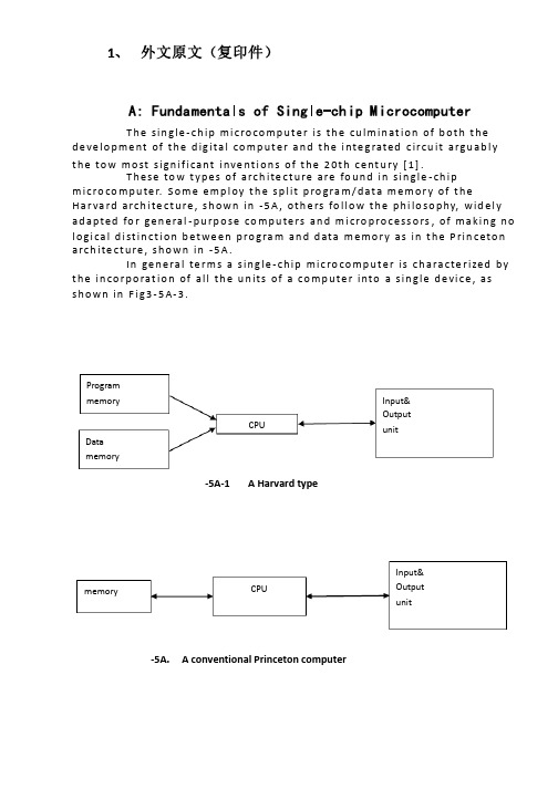
1、 外文原文(复印件)A: Fundamentals of Single-chip MicrocomputerT h e sin gle -ch ip mi c ro co m p u t e r is t h e cu lm in at io n of b ot h t h e d e ve lo p me nt of t h e d ig ita l co m p u t e r a n d t h e i nte g rated c ircu it a rgu ab l y t h e to w mo st s ign if i cant i nve nt i o n s of t h e 20t h c e nt u ry [1].T h ese to w t yp e s of arch ite ct u re are fo u n d in s in gle -ch ip m i cro co m p u te r. S o m e e mp l oy t h e sp l it p ro gra m /d at a m e m o r y of t h e H a r va rd arch ite ct u re , s h o wn in -5A , ot h e rs fo l lo w t h e p h i lo so p hy, wid e l y ad a p ted fo r ge n e ral -p u rp o se co m p u te rs an d m i cro p ro ce ss o rs , of m a kin g n o l o g i ca l d i st in ct i o n b et we e n p ro gra m an d d ata m e m o r y as in t h e P rin c eto n a rch ite ct u re , sh o wn in -5A.In ge n e ra l te r m s a s in g le -ch ip m ic ro co m p u t e r is ch a ra cte r ized b y t h e in co r p o rat io n of all t h e u n its of a co mp u te r into a s in gle d e vi ce , as s h o w n in F i g3-5A-3.-5A-1A Harvard type-5A. A conventional Princeton computerProgrammemory Datamemory CPU Input& Output unitmemoryCPU Input& Output unitResetInterruptsPowerFig3-5A-3. Principal features of a microcomputerRead only memory (ROM).RO M is u su a l l y fo r t h e p e r m an e nt , n o n -vo lat i le sto rage of an ap p l i cat io n s p ro g ram .M a ny m i c ro co m p u te rs a n d m i cro co nt ro l le rs are inte n d ed fo r h i gh -vo lu m e ap p l i cat io n s a n d h e n ce t h e e co n o m i cal man u fa c t u re of t h e d e vi ces re q u ires t h at t h e co nt e nts of t h e p ro gra m me mo r y b e co mm i ed p e r m a n e nt l y d u r in g t h e m a n u fa ct u re of c h ip s . C lea rl y, t h i s imp l ies a r i go ro u s ap p ro a ch to ROM co d e d e ve lo p m e nt s in ce ch an ges can n o t b e mad e af te r m an u fa ct u re .T h i s d e ve l o p m e nt p ro ces s m ay i nvo l ve e mu l at i o n u sin g a so p h ist icated d e ve lo p m e nt syste m wit h a h ard wa re e mu l at i o n capab i l it y as we ll as t h e u s e of p o we rf u l sof t war e to o l s.So m e m an u fa ct u re rs p ro vi d e ad d it i o n a l ROM o p t io n s b y in clu d in g in t h e i r ran ge d e v ic es w it h (o r inte n d ed fo r u s e wit h ) u se r p ro g ram m a b le m e mo r y. T h e s im p lest of t h e se i s u su a l l y d e v i ce wh i ch can o p e rat e in a m i cro p ro ce s so r mo d e b y u s in g s o m e of t h e in p u t /o u t p u t l in es as an ad d res s a n d d ata b u s fo r a cc es sin g exte rn a l m e m o r y. T h is t yp e o f d e vi ce can b e h ave f u n ct i o n al l y as t h e s in gle ch ip m i cro co m p u t e r f ro m wh i ch it i s d e ri ved a lb e it wit h re st r icted I/O an d a m o d if ied exte rn a l c ircu it. T h e u s e of t h e se RO M le ss d e vi ces i s co mmo n e ve n in p ro d u ct io n circu i ts wh e re t h e vo lu m e d o e s n ot ju st if y t h e d e ve lo p m e nt co sts of cu sto m o n -ch ip ROM [2];t h e re ca n st i ll b e a si gn if i cant sav in g in I/O an d o t h e r ch ip s co m pared to a External Timing components System clock Timer/ Counter Serial I/O Prarallel I/O RAM ROMCPUco nve nt io n al m i c ro p ro ces so r b ased circ u it. M o re exa ct re p l a ce m e nt fo rRO M d e v ice s can b e o b tain ed in t h e fo rm of va ria nts w it h 'p i g g y-b a c k'E P ROM(E rasab le p ro gramm ab le ROM )s o cket s o r d e v ice s w it h E P ROMin stead of ROM 。
空调节能技术中英文对照外文翻译文献
空调节能技术中英文对照外文翻译文献(文档含英文原文和中文翻译)中英文对照资文翻译空调节能技术的研究1、引言节能可以说是楼宇自动控制系统的出发点和归宿。
众所周知,在智能建筑中HV AC (采暖、通风和空调)系统所耗费的能量要占到大楼消耗的总能量的极大部分比例,大致在50%~60%左右。
特别是冷冻机织、冷却塔、循环水泵和空调机组、新风机组,都是耗能大户。
所以实有必要发展一种有效的空调系统节能方法,尤其用是在改善现有大楼空调系统自动化上方面。
DDC(Dircctdigitalcontrol)直接数字化控制,是一项构造简单操作容易的控制设备,它可借由接口转接设各随负荷变化作系统控制,如空调冷水循环系统、空调箱变频自动风量调整及冷却水塔散热风扇的变频操控等,可以让空调系统更有效率的运转,这样不仅为物业管理带来很大的经济效益,而且还可使系统在较佳的工况下运行,从而延长设备的使用寿命以及达到提供舒适的空调环境和节能之目的。
一般大楼常用的空调系统有CA V、V A V、VWV等,各有不同操控方式,都可以用DDC控制。
(1)定风量系统(CA V)定风量系统(ConstantAirV olume,简称CA V)定风量系统为空调机吹出的风量一定,以提供空调区域所需要的冷(暖)气。
当空调区域负荷变动时,则以改变送风温度应付室内负荷,并达到维持室内温度度于舒适区的要求。
常用的中央空调系统为AHU(空调机)与冷水管系统(FCU系统)。
这两者一般均以定风量(CA V)来供应空调区,为了应付室内部分负荷的变动,在AHU定风量系统以空调机的变温送风来处理,在一般FCU系统则以冷水阀ON/OFF控制来调节送风温度。
(2)变风量系统(V A V)变风量系统(VarlableAirV olume,简称V A V)即是空调机(AHU或FCU)可以调变风量。
常用的中央空调系统为AHU(空调机)与冷水管系统FCL系统。
这两者一般均以定风量(CA V)来供应空调区,为了应付室内部分负荷的变动,在AHU定风量系统以空调机的变温送风来处理,在一般FCU系统则以冷水阀ON/OFF控制来调节送风温度。
电气工程与自动化专业外文翻译--(中英文对照)温度控制简介和PID控制器--
电气工程与自动化专业外文翻译--(中英文对照)温度控制简介和PID控制器--河北建筑工程学院毕业设计(论文)外文资料翻译系别: 电气工程系专业: 电气工程及其自动化班级:姓名:学号:外文出处: Specialized English For ArchitecturalElectric Engineering and Automation附件:1、外文原文;2、外文资料翻译译文。
指导教师评语:签字:年月日注:请将该封面与附件装订成册。
1、外文原文Introductions to temperature controland PID controllersProcess control system.Automatic process control is concerned with maintaining process variables temperatures pressures flows compositions, and the like at some desired operation value. Processes are dynamic in nature. Changesare always occurring, and if actions are not taken, the important process variables-those related to safety, product quality, and production rates-will not achieve design conditions.In order to fix ideas, let us consider a heat exchanger in which a process stream is heated by condensing steam. The process is sketched in Fig.1Fig. 1 Heat exchangerThe purpose of this unit is to heat the process fluid from someinlet temperature, Ti(t), up to a certain desired outlet temperature,T(t). As mentioned, the heating medium is condensing steam.The energy gained by the process fluid is equal to the heat released by the steam, provided there are no heat losses to surroundings, iiithat is, the heat exchanger and piping are well insulated.In this process there are many variables that can change, causingthe outlet temperature to deviate from its desired value. [21 If this happens, some action must be taken to correct for this deviation. Thatis, the objective is to control the outlet process temperature tomaintain its desired value.One way to accomplish this objective is by first measuring the temperature T(t) , then comparing it to its desired value, and, based on this comparison, deciding what to do to correct for any deviation. The flow of steam can be used to correct for the deviation. This is, if the temperature is above its desired value, then the steam valve can be throttled back to cut the stearr flow (energy) to the heat exchanger. If the temperature is below its desired value, then the steam valve couldbe opened some more to increase the steam flow (energy) to the exchanger. All of these can be done manually by the operator, and since the procedure is fairly straightforward, it should present no problem. However, since in most process plants there are hundreds of variablesthat must be maintained at some desired value, this correction procedure would required a tremendous number of operators. Consequently, we would like to accomplish this control automatically. That is, we want to have instnnnents that control the variables wJtbom requ)ring interventionfrom the operator. (si This is what we mean by automatic process control.To accomplish ~his objective a control system must be designed and implemented. A possible control system and its basic components areshown in Fig.2.Fig. 2 Heat exchanger control loopThe first thing to do is to measure the outlet temperaVare of the process stream. A sensor (thermocouple, thermistors, etc) does this. This sensor is connected physically to a transmitter, which takes the output from the sensor and converts it to a signal strong enough to be transmitter to a controller. The controller then receives the signal, which is related to the temperature, and compares it with desired value. Depending on this comparison, the controller decides what to do to maintain the temperature at its desired value. Base on this decision, the controller then sends another signal to final control element, which in turn manipulates the steam flow.The preceding paragraph presents the four basic components of all control systems. They are(1) sensor, also often called the primary element.(2) transmitter, also called the secondary element.(3) controller, the "brain" of the control system.(4) final control system, often a control valve but not always.Other common final control elements are variable speed pumps, conveyors, and electric motors.The importance of these components is that they perform the three basic operations that must be present in every control system. These operations are(1) Measurement (M) : Measuring the variable to be controlled is usually done by the combination of sensor and transmitter.(2) Decision (D): Based on the measurement, the controller must then decide what to do to maintain the variable at its desired value.(3) Action (A): As a result of the controller's decision, the system must then take an action. This is usually accomplished by the final control element.As mentioned, these three operations, M, D, and A, must be present in every control system.PID controllers can be stand-alone controllers (also called single loop controllers), controllers in PLCs, embedded controllers, or software in Visual Basic or C# computer programs.PID controllers are process controllers with the following characteristics:Continuous process controlAnalog input (also known as "measuremem" or "Process Variable" or "PV")Analog output (referred to simply as "output")Setpoint (SP)Proportional (P), Integral (I), and/or Derivative (D) constantsExamples of "continuous process control" are temperature, pressure, flow, and level control. For example, controlling the heating of a tank. For simple control, you have two temperature limit sensors (one low and one high) and then switch the heater on when the low temperature limit sensor tums on and then mm the heater off when the temperature rises to the high temperature limit sensor. This is similar to most home air conditioning & heating thermostats.In contrast, the PID controller would receive input as the actual temperature and control a valve that regulates the flow of gas to the heater. The PID controller automatically finds the correct (constant) flow of gas to the heater that keeps the temperature steady at the setpoint. Instead of the temperature bouncing back and forth between two points, the temperature is held steady. If the setpoint is lowered, then the PID controller automatically reduces the amount of gas flowing to the heater. If the setpoint is raised, then the PID controller automatically increases the amount of gas flowing to the heater. Likewise the PID controller would automatically for hot, sunny days (when it is hotter outside the heater) and for cold, cloudy days.The analog input (measurement) is called the "process variable" or "PV". You want the PV to be a highly accurate indication of the process parameter you are trying to control. For example, if you want to maintain a temperature of + or -- one degree then we typically strivefor at least ten times that or one-tenth of a degree. If the analog input is a 12 bit analog input and the temperature range for the sensoris 0 to 400 degrees then our "theoretical" accuracy is calculated to be 400 degrees divided by 4,096 (12 bits) =0.09765625 degrees. [~] We say "theoretical" because it would assume there was no noise and error in our temperature sensor, wiring, and analog converter. There are other assumptions such as linearity, etc.. The point being--with 1/10 of a degree "theoretical" accuracy--even with the usual amount of noise and other problems-- one degree of accuracy should easily be attainable.The analog output is often simply referred to as "output". Oftenthis is given as 0~100 percent. In this heating example, it would mean the valve is totally closed (0%) or totally open (100%).The setpoint (SP) is simply--what process value do you want. In this example--what temperature do you want the process at?The PID controller's job is to maintain the output at a level sothat there is no difference (error) between the process variable (PV) and the setpoint (SP).In Fig. 3, the valve could be controlling the gas going to a heater, the chilling of a cooler, the pressure in a pipe, the flow through a pipe, the level in a tank, or any other process control system. What the PID controller is looking at is the difference (or "error") between the PV and the SP.SETPOINT P,I,&DCONSTANTSDifference error PID controlalgorithmprocess outputvariableFig .3 PIDcontrolIt looks at the absolute error and the rate of change of error. Absolute error means--is there a big difference in the PV and SP or a little difference? Rate of change of error means--is the difference between the PV or SP getting smaller or larger as time goes on.When there is a "process upset", meaning, when the process variableor the setpoint quickly changes--the PID controller has to quickly change the output to get the process variable back equal to the setpoint. If you have a walk-in cooler with a PID controller and someone opens the door and walks in, the temperature (process variable) could rise very quickly. Therefore the PID controller has to increase the cooling (output) to compensate for this rise in temperature.Once the PID controller has the process variable equal to the setpoint,a good PID controller will not vary the output. You want the outputto be very steady (not changing) . If the valve (motor, or other control element) is constantly changing, instead of maintaining a constant value, this could cause more wear on the control element.So there are these two contradictory goals. Fast response (fast change in output) when there is a "process upset", but slow response (steady output) when the PV is close to the setpoint.Note that the output often goes past (over shoots) the steady-state output to get the process back to the setpoint. For example, a cooler may normally have its cooling valve open 34% to maintain zero degrees (after the cooler has been closed up and the temperature settled down). If someone opens the cooler, walks in, walks around to find something, then walks back out, and then closes the cooler door--the PID controller is freaking out because the temperature may have raised 20 degrees! Soit may crank the cooling valve open to 50, 75, or even 100 percent--to hurry up and cool the cooler back down--before slowly closing the cooling valve back down to 34 percent.Let's think about how to design a PID controller.We focus on the difference (error) between the process variable (PV) and the setpoint (SP). There are three ways we can view the error. The absolute errorThis means how big is the difference between the PV and SP. If there is a small difference between the PV and the SP--then let's make a small change in the output. If there is a large difference in the PV and SP--then let's make a large change in the output. Absolute error is the "proportional" (P) component of the PID controller.The sum of errors over timeGive us a minute and we will show why simply looking at the absolute error (proportional) only is a problem. The sum of errors over time is important and is called the "integral" (I) component of the PID controller. Every time we run the PID algorithm we add the latest errorto the sum of errors. In other words Sum of Errors = Error 1 q- Error2 + Error3 + Error4 + ....The dead timeDead time refers to the delay between making a change in the output and seeing the change reflected in the PV. The classical example is getting your oven at the right temperature. When you first mm on the heat, it takes a while for the oven to "heat up". This is the dead time. If you set an initial temperature, wait for the oven to reach theinitial temperature, and then you determine that you set the wrong temperature--then it will take a while for the oven to reach the new temperature setpoint. This is also referred to as the "derivative" (D) component of the PID controller. This holds some future changes back because the changes in the output have been made but are not reflectedin the process variable yet. Absolute Error/Proportional One of the first ideas people usually have about designing an automatic process controller is what we call "proportional". Meaning, if the difference between the PV and SP is small--then let's make a small correction to the output. If the difference between the PV and SP is large-- then let's make a larger correction to the output. This idea certainly makes sense.We simulated a proportional only controller in Microsoft Excel.Fig.4 is the chart showing the results of the first simulation (DEADTIME = 0, proportional only):Proportional and Integral ControllersThe integral portion of the PID controller accounts for the offset problem in a proportional only controller. We have another Excel spreadsheet that simulates a PID controller with proportional and integral control. Here (Fig. 5) is a chart of the first simulation with proportional and integral (DEADTIME :0, proportional = 0.4).As you can tell, the PI controller is much better than just the P controller. However, dead time of zero (as shown in the graph) is not common.Fig .4 The simulation chartDerivative ControlDerivative control takes into consideration that if you change the output, then it takes tim for that change to be reflected in the input (PV).For example, let's take heating of the oven.Fig.5The simulation chartIf we start turning up the gas flow, it will take time for the heat to be produced, the heat to flow around the oven, and for the temperature sensor to detect the increased heat. Derivative control sort of "holds back" the PID controller because some increase in temperature will occur without needing to increase the output further. Setting the derivative constant correctly allows you to become more aggressive with the P & I constants.2、外文资料翻译译文温度控制简介和PID控制器过程控制系统自动过程控制系统是指将被控量为温度、压力、流量、成份等类型的过程变量保持在理想的运行值的系统。
电气工程及其自动化专业毕业论文外文翻译
本科毕业设计(论文)中英文对照翻译院(系部)工程学院专业名称电气工程及其自动化年级班级 11级2班学生姓名蔡李良指导老师赵波Infrared Remote Control SystemAbstractRed outside data correspondence the technique be currently within the scope of world drive extensive usage of a kind of wireless conjunction technique, drive numerous hardware and software platform support。
Red outside the transceiver product have cost low,small scaled turn, the baud rate be quick,point to point SSL, be free from electromagnetism thousand Raos etc. characteristics,can realization information at dissimilarity of the product fast,convenience,safely exchange and transmission, at short distance wireless deliver aspect to own very obvious of advantage。
Along with red outside the data deliver a technique more and more mature, the cost descend, red outside the transceiver necessarily will get at the short distance communication realm more extensive of application.The purpose that design this s ystem is transmit customer’s operation information with infrared rays for transmit media, then demodulate original signal with receive circuit。
电气工程毕业设计外文翻译原文
西南交通大学本科毕业设计外文翻译年级:学号:姓名:专业:指导老师xx 年xx、月院系 xxx 专业电气工程及其自动化年级 xx 姓名 xxx题目外文翻译指导教师评语指导教师 (签章)评阅人评语评阅人 (签章) 成绩答辩委员会主任 (签章)年月日目录ABSTRACT (1)I. INTRODUCTION (1)II. DESIGN OF HARDWARE FOR TEMPERATURE CONTROL SYSTEM (2)III. DESIGN OF SIGNAL WIRELESS TRANSMISSION (2)IV. SOFTWARE DESIGN (4)V. CONCLUSION (10)REFERENCES (11)摘要 (12)I 介绍 (12)II 对温度控制系统的硬件是合计 (12)III 设计信号的无线传输 (13)IV 软件设计 (14)V 结论 (18)Design of Temperature Control Device Underground Coal Mine Based on AT89S52ABSTRACTAbstract-Temperature underground coal mine is an important index, especially for mining workers underground. To monitor the temperature effectively, a temperature measurement and control system is necessary to design. Temperature value is displayed on LED screen on line. When temperature value reaches the maximum, conditioning device connected with the opening end of the relay controlled by the MeV will start up. Temperature signal and control information is all transmitted by wireless signal transmission module nRF905. The system program consists of transducer control and display of the temperature value. The control program of transducer is compiled according to its communication protocol. Program of wireless data transmission should be debugged between the data transmission modules. Alarm device is designed to provides effective information to workers when the temperature value is unusual. Thus monitoring of the temperature underground coal mine can be real and effective.Keywords: Index Terms-DS18B20, AT89S52, nRF905, coal mine temperature controlI. INTRODUCTIONThe environment underground coal mine is poor, and various dangers can easily occur. Therefore, in order to ensure safe production of coal mine, it is needed to supervise various parameters underground coal mine, including temperature, pressure, gas, wind speed and distance. Timely monitoring temperatures of some mine key points and coal face is an important monitoring project to guarantee safe production. Moreover, the ultrasonic measurement of distance is usually used in coal mine, to ensure the accuracy of measurement, it is also needed to make accurate temperature measurement. Traditionaltemperature measurement is done by classical isolated sensors, which has some disadvantages as follows: slow reaction rate, high measuring errors, complex installation and debugging and inconvenient long-distance transmission. In this paper intelligent temperature measurement and control is realized by taking DS18B20 temperature sensor and AT89S52 MCU as platform. DS18B20 has some advantages, mainly including digital counting, direct output of the measured temperature value in digital form, less temperature error, high resolution, strong anti-interference ability, long-distance transmission and characteristic of serial bus interface. Comparing with the traditional method of temperature measurement, MCU temperature measurement can achieve storage and analysis of temperature data, remote transmission and so on. DS18B20 sensor is a series of digital single bustemperature sensor made in DALLAS company ofUSA.[I]II. DESIGN OF HARDWARE FOR TEMPERATURE CONTROLSYSTEMThe device is composed of the temperature sensor DS18B20, MCU AT89S52, display module and relay for main fan control. The principle diagram of this hardware is shown in Fig.l.DS18B20 temperature sensor converts the environmental temperature into signed digital signal (with 16 bits complementary code accounting for two bytes), its output pin 2 directly connected with MCU Pl.2. Rl is pull-up resistor and the sensor uses external power supply. Pl.7 is linked to relay and PO is linked to LED display. AT89S52 is the control core of the entire device. Display modules consists of quaternity common-anode LED and four 9012. The read-write of sensor, the display of temperature and the control of relay are completed by program control ofthe system. [2]III. DESIGN OF SIGNAL WIRELESS TRANSMISSION Tested signal is transmitted by wireless mode, as shown in Fig. 1. Wire transmitting of signal underground coal mine has some disadvantages:1) The mineral products are mined by excavation of shaft and tunnel. Meanwhile, there are so many equipments used underground coal mine. Therefore, it is more difficult to wiring in shaft and tunnel, and environmental suitability is poor for wire transmitting of signals;2) Support workers should check up cables for transmitting signals at any moment when combined motion of the coal machine support occurs. Thus, workers' labor intensity is increased;3) The long-distance transmission of sensing element with contact method may lead to larger errors. To reduce errors, the long-distance line driver and safety barrier are needed. Thus, the cost is increased;4) The work load of maintenance underground coal mine is larger.Figure 1. Structure diagram of signal wireless transmission systemBy contrast, adopting wireless data transmission can effectively avoid the above disadvantages. [3]Wireless signal transmission module nRF905 is used in the design. Its characteristics are as follows: Integrated wireless transceiver chip nRF905 works in the ISM band 433/868/915 MHz, consists of a fully integrated frequency modulator, a receiver with demodulator, a power amplifier, a crystal oscillator and a regulator. Its working mode of operation isShock Burst. Preambles and CRC code are automatically generated in the mode, and can easily be programmed through the SPI interface. Current consumption of the module is very low. When the transmit power is +10 dBm, the emission current is 30 rnA and receiving current is 12.2 rnA. It also can enter POWERDOWN model to achieve energy-saving. [4]IV. SOFTWARE DESIGNFor doing the read-write programming for DS18B20, its read-write time sequence should be guaranteed. Otherwise, the result oftemperature measurement will not be read.Figure 2. Software design flow chartTherefore, program design for operation on DS18B20 had better adopt assembly language.[5] Software design flow chart is shown in Fig.2.Structure of Main program for temperature measurement is shown as following: INIT 1820:SETB DINNOPCLRDINMOV RO,#250TSRI: DJNZ RO,TSRISETB DINNOPNOPNOPMOV RO,#60TSR2: DJNZ RO,TSR2JNB PI.0,TSR3LJMPTSR4TSR3: SETB FLAGILJMPTSR5TSR4: CLR FLAG1LJMPTSR7TSR5: MOY RO,#6BHTSR6: DJNZ RO,TSR6TSR7: SETB DINSETB DINRETGET TEMPER:SETB DINLCALL INIT 182018 FLAG1,TSS2RETTSS2: MOY A,#OCCH LCALL WRITE 1820 MOY A,#44HLCALL WRITE 1820 LCALL DELAY LCALL DELAY LCALLDELAY LCALLDELAY LCALL DELAY LCALLDELAY LCALL INIT 1820 MOY A,#OCCH LCALL WRITE 1820 MOY A,#OBEH LCALL WRITE 1820 LCALL READ 1820 RETWRITE 1820:MOY R2,#8CLRCREAD_l 820:MOVR4,#2MOV Rl,#29H REOO: MOV R2,#8 REOl: CLR CSETB DINNOPNOPCLRDINNOPNOPNOPSETB DINMOVR3,#9ADJUST_TEMPER: CLR TEM_BITJNB 47H,AJUSTSETB TEM_BITXRL TEMPER_L,#OFFH MOV A,TEMPER_L ADDA,#OlHMOV TEMPE~L,AXRL TEMPER_H,#OFFH MOV A,TEMPER_H ADDCA,#OOHMOV TEMPER_H,A ADJUST:MOV A,TEMPER_L MOV B,#lOODIVABMOV B_BIT,AMOV A,BMOV B,#lODIVABMOV S_BIT,AMOV G_BIT,BDISP MAIN: LCALL D_DISP LCALL G_DISP LCALL S_DISP LCALL B_DISP MOV A,#OFFH LCALLDISPMOV A,#OFFH LCALL DISPMOV A,#OFFH LCALLDISPMOV A,#OFFH LCALL DISP LCALLDELAY RETD DISP:MOVC,D_BITJC D DISPIMOV A,#03H LCALL DISPRETD DISPl:MOV A,#49H LCALL DISPRETG DISP:MOV A,G_BIT MOV DPTR,#TAB MOVC A,@A+DPTRANLA,#OFEH LCALL DISPRETS DISP:MOV A,S_BITMOV DPTR,#TAB MOVC A,@A+DPTR LCALL DISPRETB DISP:JNB TEM_BIT,B_DIS MOV A,#Ofdh LCALL DISPRETB DIS:JB l8H,B_lMOV A,#Offh LCALL DISPRETB 1: MOV A,#03H LCALL DISPRETDISP: CLRCMOVR2,#8DIS: RRCA MOVDAT,C CLRCLK SETBCLKCLRCLKDJNZ R2,DISRETDELAY: MOV R3,#80hDl: MOV R4,#OfEhDJNZ R4,$DJNZ R3,DlRETTAB:DB 03H,9FH,25H,ODH,99HDB 49H,4IH,IFH,OIH,09HENDV. CONCLUSIONThe performance of measurement-control device mainly depends on the performance of sensing element, the processing circuit and the transmission efficiency of collected data. Digital temperature sensor DSl8B20 and processing chip AT89S52 have characteristics of good technical indexes, and the field operations indicate that circuits system has many advantages, such as accurate data detection, good stability and easy adjustment.After industrial operation test, the system is excellent for worst mine environment, which provides powerful assurance for safe production in the coal industry, and brings good economic and social benefits.REFERENCES[1] WANG Furui, "Single chip microcomputer measurement and control system comprehensive design," Beijing University of Aeronautics and Astronautics Press, 1998.[2] XIA Huguo, "Technology application in automation combined-mining face," Shaanxi Coal, 2007.[3] SHA Zhanyou, "Principle and application of intelligent integrated temperature sensor," Mechanical Industry Publishing House, 2002.[4] CAO Shujuan, HE Yinyong, GUO San-rning, On-line temperaturemeasuring system involving coal mine, Journal of Heilongjiang Instituteof Science & Technology,7(2005)[5] SUN Xiaoqing, XIAO Xingming, WANG Peng, "Design of Measuring System for Rotating Speed of Hoist Based on Virtual Instrument," CoalMine Machinery, 12(2005).基于AT89S52煤矿井下的温度控制装置的设计摘要煤矿井下抽象温度是评价学术期刊的重要指标,特别是对在地下工作的采矿工。
- 1、下载文档前请自行甄别文档内容的完整性,平台不提供额外的编辑、内容补充、找答案等附加服务。
- 2、"仅部分预览"的文档,不可在线预览部分如存在完整性等问题,可反馈申请退款(可完整预览的文档不适用该条件!)。
- 3、如文档侵犯您的权益,请联系客服反馈,我们会尽快为您处理(人工客服工作时间:9:00-18:30)。
暖通空调系统中英文资料外文翻译文献外文文献:HV AC system optimization––condenser water loop AbstractThis paper presents a model-based optimization strategy for the condenser water loop of centralized heating, ventilation and air conditioning (HV AC) systems. Through analyzing each component characteristics and interactions within and between cooling towers and chillers, the optimization problem is formulated as that of minimizing the total operating cost of all energy consuming devices with mechanical limitations, component interactions, outdoor environment and indoor cooling load demands as constraints. A modified genetic algorithm for this particular problem is proposed to obtain the optimal set points of the process. Simulations and experimentalresults on a centralized HV AC pilot plant show that the operating cost of the condenser water loop can be substantially reduced compared with conventional operation strategies.Keywords: Centralized HV AC system; Condenser water loop; Model-based optimization; Genetic algorithms;Simulations and experiments1. IntroductionA typical centralized heating, ventilation and air conditioning (HV AC) system is comprised of a condenser water loop and chilled water loop that, together with chillers and indoor air loops,provide a comfort environment for the conditioned space. The process of a condenser water loop consists of chiller condensers, pumps, cooling towers and fans [1]. The schematic diagram of a condenser water loop is shown in Fig.1. Chiller condensers transfer the indoor cooling load and the heat generated by the compressors into the condenser water. Pumps provide the energy to circulate water between the chiller condensers and the cooling towers. The heat is rejected to the ambient air through heat transfer and evaporation by the cooling towers.Since the condenser water loop is a main function block of HV AC systems, its energy consumption contributes significantly to the overall operating cost. Efficient operation of individual devices as well as the whole condenser water loop has been intensively studied in recent years. Among many published research results, Cassidy and Stack [2] showed that varying the speed of cooling tower fans can reduce energy consumption at part load conditions. Braun and Doderrich [3] proposed a systematic approach to find a near optimal variable speed drive (VSD) fan speed based on parameters estimated from design data. This method was further extended by Cascia [4] to simplify the component model and provide equations for determining the set points of near optimal control. However, all these methods were based on the assumption that the condenser water flow rate is unchanged. By considering the effects of condenser water flow rate on the performance of the chiller condensers and cooling towers, Shelton and Joyce [5] recommended a fixed condenser water flow rate (1.5 gpm/ton) as a rule of thumb for system operation. Later, Kirsner [6] showed that high condenser water flow rate (3 gpm/ton) has good performance at full loadcondition, while low condenser water flow rate (1.5 gpm/ton) has advantages at part load conditions. Unfortunately, systematic determination of the water flow rate under different out-door environment and cooling loads is still an open question. Another important variable to be considered in condenser water loop optimization is the condenser water supply temperature. Schwedler [7] used several examples to demonstrate that the lowest possible leaving tower water temperature does not always conserve system energy. Nevertheless, his results were not conclusive as only half speed and full speed fan conditions were considered.In this paper, a novel optimization strategy for the condenser water loop is presented. Our objective is to minimize the total energy consumption of the condenser water loop. Based on the mathematical models of related components, the operating characteristics of cooling towers, the effects of different ambient environment and the interactions between chillers and cooling towers,the energy efficiency of the condenser water loop can be maximized by both variable water flow rate and air flow rate. A modified genetic algorithm is used to search for optimal values of the independent variables. Simulation and experimental results on a centralized HV AC pilot plant demonstrate that a significant operating cost can be saved by the proposed method.2. Problem formulationIn the condenser water loop, there are three types of devices which consume energy, namely chillers, pumps and fans. Therefore, the objective function is to minimize thetotal energy consumption of these devices.fan pump chiller total P P P P ++=minThe power consumptions of the chillers, pumps and fans are given, respectively. )()(,,,i adj adji i nom ii cap chiller Temp PLR COP Q P ⋅⋅⋅=∑CWSCHWS CHWS CHWS CHWS CHWS i adj i i cap i i cap i adj T T c T c T c T c T c c Temp Q Q b Q Q b b PLR where52432210,2,2,10,)()(+++++=++=∑∑))()()(())()()((3,,,32,,,2,,,10,,3,,,32,,,2,,,10,,knom a k a k nom a k a k k nom a k a k nom fan fan jnom w j w j nom w j w j nom w j w j nom pump j pump m m e m m e m m e e P P m m d m m d m m d d P P and+++=+++=∑∑ Note that the performance of the condenser water loop is a ffected by several factors, such as the physical limitations of individual components, interactions among them and the outdoor environment. These factors have to be considered in solving the optimization problem. The mathematical formulations and physical explanations of these constraints are given below.2.1. Mechanical constraintsAs P pump and P fan are influenced by m w;j and m a;k monotonically, the physical limitations for m w;j and m a;kare Constraint (1)2.2. Cooling tower constraintThe cooling tower constraint is given as [10]Constraint (3)where K is the total number of operating cooling towers and m w;k is the water flowrate to each cooling tower. Without loss of generality, in analyzing the cooling tower performance, it is assumed that the condenser water is evenly distributed in each cooling towerThere are two factors affecting cooling tower performance in Constraint (3), one is m w;j vs. m a;k and the other is T CWR vs. T w b . To simplify the analysis, it is assumed that T CWR and T w b are constants in discussing the effect of m w;j vs. m a;k . Fig. 2 shows five curves of equal heat rejection rate [11], where the x-axis is percentage of water flow rate at full load and the y-axis is percentage of air flow rate at full load. These curves of equal heat rejection rate are divided into three portions. •Portion (1): the air flow rate is very small and the water flow rate must be very big in order to achieve a given heat rejection rate. In this case, the air flow rate is too small to exchange heat efficiently with the condenser water. The outlet air flow wet bulb temperature is almost the same as that of the inlet water.•Portion (2): the air flow rate is very big, while the water flow rate is very small, the heat ex-change is saturated and the outlet water temperature is nearly equal to the ambient air wet bulb temperature.•Portion (3): the heat rejection rate of the cooling tower increases with either increased air flow rate or increased water flow rate and vice versa.Apparently, the energy efficient operating range must lie inside Portion (3). In this portion, a reduced air flow rate leads to a lower fan power consumption, but the water flow rate has to be increased, resulting in an increased pump power consumption. Similarly, a reduced water flow rate lowers the pump power consumption but results in an increased fan power consumption. Constraint (3) limits the value of m w;j and m a;k due to the cooling tower characteristics.The term T CWR T wb in Constraint (3) reflects the effect of T wb on the cooling tower performance. Assuming the cooling tower heat rejection rate and condenser water supply temperature are kept constant, the optimal operating point of cooling towers changes if T wb changes. Fig. 3 gives an example where the cooling tower heat rejection rate is assumed to be a fixed value for different wet bulb temperatures of ambient air, 20 and 25 LC, respectively. The optimal operating points are labeled as pentagons to indicate the corresponding power consumption of the fans and pumps. While the curves of fan power consumption are the same for different wet bulb temperatures, the condenser water flow rate changes with changing air flow rate andoutdoor environment for a constant cooling tower heat rejection rate.The optimal air flow rate is 85% of the full load at 25 ℃ and 50% at 20 ℃. For an optimal operating point, the power consumption is 12% of the full load at 20 ℃ wet bulb temperature. If the air flow rate is kept at 85% of the full load at 20 ℃ instead of 50%, the combined power consumption of the fan and pump is 19% of the full load. Compared with 12% of the full load at the optimal point, almost 7% of the energy of the full load could be saved with varying the mass flow rates of water and air.2.3. Interaction constraintsThe variable T CWS influences both the chiller power consumption and the cooling tower performance.Constraint (4)This temperature is also restricted by boundaries that are often provided by chiller manufacturers for safe operation of the chillers.It has been generally acknowledged [3,5–7,12–16] that a decreasing T CWS results in an increasing COP and lower energy consumption of the chillers. However, a lower T CWS leads to a smaller T CWR and then higher m a;k and m w;k for fixed Q and T wb. As m a;k and m w;k increase, the fan power and condenser water pump power increase cubically. Fig.4 illustrates the trade-off between the chiller and cooling tower fan power associated with an increasing tower air flow rate [2]. Here, a fixed condenser water flow rate is assumed. As the air flow rate increases, the fan power increases. At the same time, there is a reduction in the condenser water supply temperature, resulting in a lower chiller power consumption.On the other hand, T CWR, in turn, affects the heat exchange efficiencies in the cooling towers. When the condenser water supply temperature decreases, the condenser water return temperature also decreases for the same cooling load. Thisresults in lower efficiencies of the cooling tower under the same ambient wet bulb temperature, as the enthalpy difference between ambient air and condenser water becomes smaller. The optimal operating point occurs at a point where the rate of power increase in the fans and pumps is equal to the rate of power reduction in the chillers.3. Optimization algorithmIn the optimization problem, i, j, k, m a;k and m w;j are independent variables, T wb, T CHWS, T CHWR and m CHW are variables that can be measured and Q, T CWS and T CWR are variables to be deter-mined by constraints.As this optimization problem is a combinatorial optimization problem with non-linear constraints and contains both continuous and discrete variables, conventional gradient based optimization methods cannot be applied directly. An exhaustive search method or an exhaustive search method combined with conventional gradient based methods can be applied to find the optimal solutions, even though it is impractical in real time applications for such a complicated problem due to its time consuming nature. Genetic algorithms for problem solving are not new, but it is only very recently that they are implemented in industry applications [17–20]. The genetic algorithm is more attractive than other optimization algorithms in several aspects:•It can handle problem constraints by simply embedding them into the chromosomeencoding procedure.•It is feasible to solve multi-model, non-differentiable, non-continuous problems etc., since it is independent of the function gradient.•It is very easy to understand and involves very little mathematics.•It has implicit parallel computation features, which make it more efficient than the exhaustive search methods.The implementation of a modified genetic algorithm for this particular problem can be dividedinto four phases: encoding, construction of fitness function, evolution and termination.3.1. EncodingThe first step for a genetic algorithm is encoding. It is a process of transforming a series of problem inputs into a serial of codes that can be easily interpreted and used in evaluating the information it represents by the fitness function. In this application, both discrete variables (i, j, k) and continuous variables (m a;k , m w;j) are converted into binary strings and are connected together to form a chromosome.For the discrete variables, each bit represents the status of each component. For example, ‘‘1’’ stands for either a chiller, a pump or a fan being staged on, while ‘‘0’’ is for off.For the continuous variables, such as the mass flow rates of air and water, the upper and lower bounds of their binary strings stand for minimum and maximum values in Constraint (1). The lengths of the binary strings are determined by the control precision of the corresponding variables: the more precise set point control, the longer binary string.3.2. Construction of fitness functionIn order to fulfill Constraints (2)–(5), penalty functions are commonly used to penalize an in feasible solution. In this step, a penalty function is added if any constraint cannot be fulfilled. The fitness function is expressed in the following equation.where v1, v2and v3are the penalty multipliers, which should be large positive numbers. With this fitness function, the minimal system power consumption without violating any constraints has the maximum fitness value. The fitness values will be used as guides for evolution.3.3. EvolutionThe evolution consists of three major functions: selection, crossover and mutation [17]. These functions are performed for each generation to produce the next generation with improved fitness values.•Selection is the process of determining the number of times that a particular individual is chosen for reproduction. The ‘‘roulette wheel’’ selection method [17] is adopted in the application based on linear scaled fitness values.•Crossover is a basic function to produce new individuals which have some parts of both parents genetic material. A single point crossover method is adopted here and shown by the following example.Parent 1: 1 1 1 1 1 1 ‘‘crossover at the second bit’’ New individual 1: 11 0 0 0 0 Parent 2: 0 0 0 0 0 0 ) New individual 2: 0 0 1 1 1 1•Mutation is a random process where one bit of a binary string is flipped to produce a new individual. Single bit mutation is used in the example below.Original individual: 1 1 1 1 1 1 ‘‘mutation at the fifth bit’’New individual: 1 1 1 1 0 1The crossover and mutation points are all selected randomly in each generation.The probability of crossover and mutation are selected according to the recommendations in Refs.T he evolution procedure of the modified genetic algorithm is illustrated in Fig. 5. The major differences with the simple genetic algorithm given in Ref. [17] are:1.To restrict the searching space by knowledge from the previous optimization. Thereduced searching space reduces computing time.2.To keep the individual with the best fitness value in each generation. This operation prevents the optimal results from being lost in the subsequent evolutions.The parameter settings in the modified genetic algorithm are listed as follows: •Number of individuals in a generation: 100;•Maximum number of generations: 500;•Precision of each continuous variable: 28;•Generation gap: 0.9;•Probability of crossover: 0.7;•Probability of mutation: 0.01.3.4. TerminationThe computation of the genetic algorithm is terminated when the following criteria are reached.•The maximum number of generations is reached;•The fitness value of the best individual converges to a certain asymptote.Each new optimal result is compared with the current operating set points before being put into force. This is a safety measure to prevent uncertainties of the genetic algorithm due to insufficient evolution time. If such a condition occurs, the system will operate at the present set points without any changes until the next sampling period.中文译文:暖通空调系统的优化––冷却水循环摘要本文提出了一种基于模型的集中加热、通风和空调(HVAC)系统的冷却水循环的优化策略。