智能控制器软件使用说明书教学提纲
智能控制器软件使用说明书

5.1.3灯光模式复制
此选项可以将一个场景的灯光参数完全复制到当前场景,渐变与声控参数不能复制,如图10所示可将左边组复制到当前组。
2)红外码:在此可对红外码进行学习,有两种学习方式:
直接输入红外码值,点“写入”按钮进行写入。
点“学习”按钮,再用遥控器对准智能控制器显示屏的位置进行学习,学习成功后点“退出学习”按钮退出学习状态。
3)串口墙板1:在此可对墙板与组号进行学习关联,有两种学习方式:
直接输入墙板码值,点“写入”按钮进行写入;
制热模式时当室温度大于设定温度时,电子阀自动,并把空调置为空档,当室温下降到小于设定温度时电子阀再次打开,并自动调到设定风速档位。
送风模式时不对温度与电子阀进行关联控制,设定温度与当前温度均无效,空调随设定的档位持续工作。
制冷、制热模式必须正确设定,否则会导致空调工作不正常,若使用不带温度控制的墙板时,需设置为送风模式,否则可能会导致空调不工作。
5.1.2全局控制
全局控制所有参数设定界面如图8所示
图8
1)全局亮度:在此设置当前场景模式的默认全局亮度,默认亮度对该场景模式所有灯有效,每一路可调灯的亮度是由默认亮度与该路灯单独控制的亮度决定。选项如图9所示。
图9
2)开关模式:有两种模式可供选择:固定模式和开关模式。固定模式:按墙板上对应按键时,受控的各路灯打开,再次按下时保持不变;开关模式:按墙板上对应按键时,受控的各路灯打开,再次按下时受控的各路灯关闭。
2)全局控制
智能家居控制系统软件使用说明书
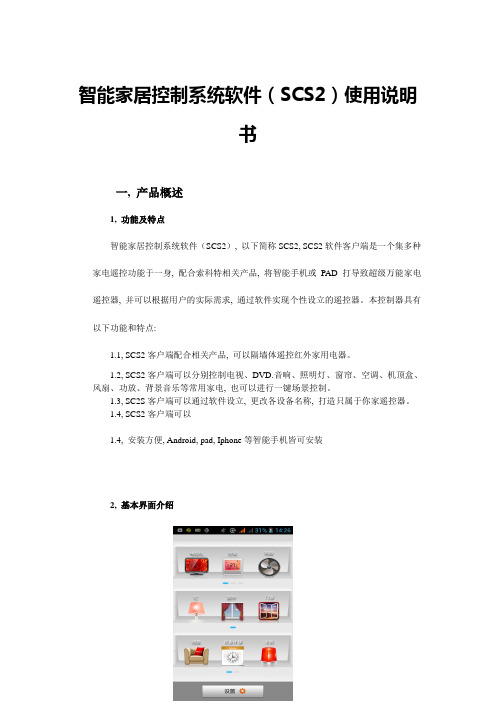
智能家居控制系统软件(SCS2)使用说明书一, 产品概述1, 功能及特点智能家居控制系统软件(SCS2), 以下简称SCS2, SCS2软件客户端是一个集多种家电遥控功能于一身, 配合索科特相关产品, 将智能手机或PAD打导致超级万能家电遥控器, 并可以根据用户的实际需求, 通过软件实现个性设立的遥控器。
本控制器具有以下功能和特点:1.1, SCS2客户端配合相关产品, 可以隔墙体遥控红外家用电器。
1.2, SCS2客户端可以分别控制电视、DVD.音响、照明灯、窗帘、空调、机顶盒、风扇、功放、背景音乐等常用家电, 也可以进行一键场景控制。
1.3, SC2S客户端可以通过软件设立, 更改各设备名称, 打造只属于你家遥控器。
1.4, SCS2客户端可以1.4, 安装方便, Android, pad, Iphone等智能手机皆可安装2, 基本界面介绍主界面控制界面(电视类)设立键主功能分类区电视机数量/型主功能分类功能操作区房间分类区楼层分类区功能操作区主功能分类控制界面(灯光类)区域分类区背景功能操作区主功能分类控制界面(灯光类)注: 1, 本软件合用手机分辨率1280*720、800*480、854*480、480*320、960*540。
2, 点击主界面下方<LOGO区域>会弹出设立按钮二, 产品各部件配置说明智能开关使用说明合用范围: 索科特智能开关产品优势:1, 外观精美, 工艺细致, 颜色和图案可根据用户喜好而定制。
2, 背光效果为你在黑夜中指明前进的方向, 实用贴心。
3, 开关上的每个开关按键完全满足5-500瓦相应光源。
4, 控制方式多样化, 可以实现触摸控制、现场遥控。
安全警告:1, 安装和拆卸前请务必切断电源。
2, 安装前保证线路没有短路, 接错。
3, 安装和使用本产品时须注意防水、防蒸汽、防敲击。
4, 勿用锋利的物体刮擦触摸面板。
5, 开关在开灯或关灯时请勿用力过猛, 以免按碎触摸面板。
机器人智能控制器的说明书

机器人智能控制器的说明书一、简介机器人智能控制器是一种高性能的控制装置,可用于控制各类机器人的运动和操作。
本说明书将详细介绍机器人智能控制器的功能和操作方法,以帮助用户正确使用和了解该控制器。
二、技术参数1. 控制方式:智能控制算法2. 输入电压:220V 50Hz3. 输出电流:最大输出电流为10A4. 通讯接口:支持RS485、Ethernet等多种通讯方式5. 控制精度:角度误差小于0.1°6. 控制范围:适用于各类机器人的姿态调整和动作控制三、功能介绍1. 姿态控制:机器人智能控制器可以通过对机械臂和关节的控制,实现机器人的各种姿态调整。
用户可以通过输入指令或者外部传感器来调整机器人的姿态,控制器将根据指令进行精确的控制,并及时将结果反馈给用户。
2. 动作控制:机器人智能控制器支持多种动作模式,用户可以通过编程或者手动控制实现机器人的各种动作。
控制器提供了丰富的API和函数库,使得用户可以根据实际需求来编写自定义的动作控制程序。
3. 传感器集成:控制器内置了多种传感器接口,可以与各类传感器进行连接,如视觉传感器、力传感器等。
通过传感器的数据反馈,控制器可以实时感知机器人的工作环境,并做出相应的控制调整。
4. 多机器人协同:机器人智能控制器支持多机器人协同工作。
用户可以通过网络通讯或者RS485总线实现多台机器人之间的通讯与协调,提高工作效率和灵活性。
四、操作说明1. 电源接入:将机器人智能控制器的电源线插入220V交流电源插座,并确保电源稳定。
2. 硬件连接:根据机器人的不同类型,将机器人与控制器通过适当的接口进行连接。
确保连接稳定可靠。
3. 编程配置:根据具体应用需求,编写控制程序并上传到控制器。
通过控制器提供的开发工具和API,用户可以自由地编写和修改相应的控制逻辑。
4. 运行控制:启动机器人智能控制器,并根据需要选择相应的控制模式。
可以通过控制器上的按钮或者远程控制软件来实现机器人的姿态和动作调整。
unit3 智能控制器说明书
unit3 智能控制器说明书
智能控制器是一种用于控制和管理各种设备和系统的装置。
它
通常具有自动化、智能化和远程控制的功能,能够实现对设备的精
确控制和监控。
智能控制器通常应用于工业自动化、建筑物管理系统、智能家居等领域。
下面我将从多个角度全面介绍智能控制器的
说明书内容。
首先,智能控制器说明书通常包括产品的基本信息,如型号、
规格、外观尺寸、工作原理等。
这些信息可以帮助用户了解产品的
基本特性和适用范围。
其次,说明书会详细介绍智能控制器的安装和操作步骤。
包括
安装环境要求、安装方法、接线方式、开机操作、参数设置等内容。
这些内容对用户正确使用和维护智能控制器至关重要。
另外,智能控制器说明书还会对产品的功能特点进行详细说明,包括各种传感器、执行器的连接方式、通讯协议、远程监控等功能。
用户可以通过说明书了解产品的功能优劣势,以便更好地应用和操作。
此外,说明书通常也会包括故障诊断与排除方法,以及维护保养等内容。
这些内容对于用户在日常使用中遇到问题时能够及时处理故障,保证设备的正常运行具有重要意义。
最后,智能控制器说明书还可能包括产品的技术参数、安全注意事项、售后服务政策等内容,以帮助用户更全面地了解产品并获取相关的支持和服务。
综上所述,智能控制器说明书是用户了解、安装、操作和维护智能控制器的重要参考资料,它的内容应该全面、详细、准确,以确保用户能够正确、安全地使用智能控制器,同时也为售后服务提供了重要的依据。
新风系统智能控制器使用说明书

新风系统智能控制器使用说明书一.概述新风系统智能控制器适用于对家庭及公共场合新风系统风机的智能控制,控制器分别设有手动及自动风量调节(三档)功能,时间及室内温度显示,滤网使用时间提醒。
自动控制功能可以设定每周7天,每天4时段运行状态,每个时段可以根据需要设定新风系统启闭或风量。
新风系统智能控制器根据具体情况灵活控制新风系统风机运转速度,实现既节能环保又能保持室内良好空气品质。
二.显示及按键符号 内容1当前星期状态2本地时间24小时制显示3自动运行模式状态显示4设置选择5风量切换6开关(设置状态时:确认)7数字减少或向后选择设置参数8数字增加或向前选择设置参数9自动运行模式:正在运行时段10手动运行模式状态显示11风量显示12环境温度显示三.技术参数输入电源 功率消耗 时段数量 输出方式 外形尺寸A C220V1w每天4时段,每周最多28时段 继电器 ≤1A86m m×86m m×14m m四.操作设置说明1.手动运行模式控制器接通电源后,液晶屏显示温度、时间、星期状态,约五秒后按开关键,液晶屏出现风量图标及手动运行模式图标,风量默认为中。
按风量切换键,可依次在高、中、低风量间进行切换,对应的风量图标的风量显示条分别为3条、2条、1条。
2.自动运行模式同时按下▽及△键,控制器进入自动运行模式,液晶屏显示自动运行模式图标。
自动运行时段设定:自动运行模式下连按两次按设置选择键,液晶屏自动运行模式图标A U T O闪烁,进入时段设定。
这时星期状态图标闪烁,按▽或△选择你要设定星期状体,按开关键确认。
星期状态确认后,自动进入这一天第1时段设定,这时液晶屏运行时段标显示1,时间的小时数字闪烁,按▽或△选择你要设定的时间,按开关键确认;小时确认后,自动进入分钟设定,这时时间的分钟数字闪烁,按▽或△选择你要设定的分钟,按开关键确认;时间设定确认后,自动进入风量设定,这时风量图标闪烁,按▽或△选择你要设定的风量(风量图标中无风量条表示关闭),按开关键确认,第一时段设定完毕,并自动进入第二时段设置。
智能照明控制器的设置指南说明书

智能照明控制器的设置指南说明书概述:智能照明控制器是一个多功能设备,可实现各种照明场景的自动化控制。
本说明书旨在帮助用户了解并正确设置控制器。
1. 控制器的安装控制器应安装在通风良好、温度适宜的室内环境。
在安装控制器时,应先关闭照明开关并断开电源。
将控制器的输入端与市电连接,输出端与照明灯具相连。
务必确保连接正确,以免因反接等操作导致的设备损坏。
2. 控制器的设置通过连接控制器的配套手机APP或者网页控制端,用户可以进行多种设置。
以下是常见的设置方法:2.1 灵敏度设置用户可以设置照度灵敏度和动作灵敏度,以达到不同的自动控制效果。
视环境需要进行合理的设置,免得误闪或未闪。
2.2 定时设置用户可以通过设置时间、日程表等方式,使控制器能够在设定的时间内自动开启或关闭某灯具。
比如在夜间自动关闭部分灯光,早晨自动开启厨房的灯具等。
2.3 场景设置用户可以将多个相同或不同的灯具分为不同的场景,然后通过命令或者手机APP进行快速切换。
比如设置一键“观影模式”,可以快速关闭走廊、厨房等灯光的同时,打开主卧的柔光灯。
3. 控制器的注意事项为了使控制器能够正常工作且使用寿命更长,用户需注意以下事项:3.1 注意电源稳定请将控制器和灯具连接的电源保持稳定,在供电电压波动大的地方请设置稳压器,免得影响设备寿命并降低性能。
3.2 定期检查请用户在使用一段时间后定期检查控制器的连接是否正常、灯具、散热器是否存在脱落、变形、老化等问题,如发现问题请及时更换。
3.3 谨慎操作请用户谨慎操作,避免误操作及恶意攻击造成设备损坏,同时请勿将控制器拆开进行维护。
结论:智能照明控制器是实现自动化照明控制的重要设备,用户可以根据自身需要进行合理的设置。
在设置及使用控制器时,请用户严格按照说明书进行,以免影响设备使用寿命并造成人身财产损失。
kolink 智能控制器使用手册说明书
USER MANUAL OF SMART CONTROLLER Read themanual carefully before installing or connecting your Smart Kit (Wireless Module). Make sure to save this manual for future reference.IMPORTANT NOTE:QR CODEDECLARATION OF CONFORMITYHereby, we declare that this AC is in compliance with the essential requirements and other relevant provisions of Directive 2014/53/EU.A copy of the full DOC is attached.1.Model: EU-OSK103Standard: IEEE 802. 11b/g/nAntenna Type: Printed PCB Antenna Frequency: WLAN 2400~2483.5 MHz Operation Temperature: 0ºC~45ºC/32ºF~113ºF Operation Humidity: 10%~85%Power Input: DC 5V/300mAMaximum Transmitted Power: 19.8dBm Max∙Applicable system: iOS, Android.(iOS 8.0 or above, Android 6.0 or above)-Please keep your APP up to date with thelatest version.-Due to some situations, we affirm: Not allAndroid and iOS systems are compatiblewith the APP. We will not be liable for anyissue as a result of the incompatibility.∙Wireless Safety StrategySmart kit only supports WPA-PSK/WPA2-PSKencryption and none encryption.WPA-PSK/WPA2-PSK encryption isrecommended.Due to different network situation, control process may time-out in some occasions. If this situation occurs, the display between board and APP may not be the same, please don’t get confused.Smart phone camera needs to be 5 million pixels or above to scan the QRcode sufficiently.Request time-out could happen due to different network situation. Hence,it is mandatory to do networkconfiguration once again.The APP system is subject to update without prior notice due to someproduct function improvement. Theactual network configuration processmay slightly be different from themanual, so, the actual process shallprevail.Wi-Fi signal must be strong in order for the Air-conditioning unit to workproperly. If Wi-Fi signal is weak in theroom wherein the AC unit is placed,usage of repeater is advised.3.The following QR code is only available for DOWNLOADING the app.Android iOS∙For Android Phone users: scan Android QR code or go to google play then search“NetHome Plus” app and download it.∙For iOS users:scan iOS QR code or go to App Store then search “NetHome Plus”app and download it.1.Remove the protective cap of the SmartKit (wireless module)2.Open the front panel and insert the SmartKit (wireless module) into the reservedinterface.3.The QR code packed with Smart Kit(wireless module) is attached to the sidepanel of the machine to ensure that it willbe scanned by the mobile phone. Otheroption is to take the picture of the QRcode and save it to their phone. It is alsoavailable on the front page of the usermanual.This interface is only compatible with Smart Kit (Wireless Module) provided by the manufacturer.5. USER REGISTRATIONPlease ensure your mobile device is connected to the Wi-Fi router. The wirelessrouter must be connected to the internet before doing the registration and network configuration.It is better to log-in your email on the box and activate your account by clicking the link in case you forget your password. You can also log in using the Third Party applications (Facebook & Twitter)NOTE:For iOS users, you will receive a verification e-mail with the attached link in your registered e-mail address while for Android users, you can already log in after registration.6.∙It is necessary to forget any other network which is around the premises and make sure your device is connected to the wireless network you want to configure.∙Make sure your device’s wireless function works well and can be connected back to your original wireless network automatically.֍Using Android device to do networkconfiguration1.Make sure your mobile device hasalready been connected to thewireless network which you wish to use.Also, you need to forget other irrelevantwireless network in case it influencesyour configuration process.2.Disconnect the power supply of AC.3.Connect the power supply of AC andcontinuously press the “LED DISPLAY” or“DO NOT DISTURB” button seven timesin 10 seconds.4.When the AC displays “AP”, it meansthat the AC wireless has alreadyentered into “AP” mode.Some type of AC does not need step 2 to be in AP mode.NOTE:The user must finish all the steps within 8 minutes after powering on the AC or else you will have to reset and go back again to step 1.(SCAN THE QR CODE METHOD)(MANUAL SETUP METHOD)1. Make sure yourmobile device isalready connected to the wireless network you want to use. Also, you need to forget all irrelevant wireless networks in case it influences you configuration process.2. Disconnect the power supply of AC (some units).3. Connect the power supply of AC and continuously press the “LED DISPLAY” button or “DO NOT DISTURB” button seven times in 10 seconds.4. When the AC displays “AP”, it means the AC wireless has already entered into “AP” mode.The user must finish all the steps within 8 minutes after powering on the AC or else you will have to reset and go back again to step 1.֍ Using iOS device to do network configuration(SCAN THE QR CODE METHOD)(MANUAL SETUP METHOD)When finishing network configuration, app will display success cue words on thescreen.Due to different internet environment, it is possible that the device status still displays“offline”. If this situation occurs, it isneeded to pull and refresh the device liston the app and make sure the devicestatus becomes “online”. Alternatively,user can turn off the AC power and turn iton again and then the status will become“online” after a few minutes.Please ensure both your mobile device and air conditioner is connected to the internet before using the app to control the air conditioner via internet.Not all function of the app is available on air conditioner. Example: ECO, Turbo, Swing function. Please check the user manual for more information.It Includes: Timer on, Timer off, 8ºC Heat, Sleep, Check and 4 way air direction.If the air conditioner does not support the above function, it will not be shown on the function list.Weekly, the user can make an appointment to turn on or turn off AC on a specific time. User can also choose circulation to keep the AC under schedule control every week.The user can let the AC run under 8ºC heat by one click. When people go outside, this function can protect your furniture from frost damage. (NOTE: THIS FUNCTION MAY NOT BE AVAILABLE TO ALL UNITS)Theuser can customize their comfortable sleep by setting target temperature.The user can simply check the AC running status with this function. When running this procedure, it can detect the normal items, abnormal items and detailed information.The air conditioner can be controlled by multi-users at the same time by “Share device” function.IC: 1 257 5A-MD NA 15This device complies with Part 15 of the FCC rules and industry Canada’s license-exempt RSS’s.Operation is subject to the following two conditions:1.This device may not cause interference;and2.This device must accept any interference,including interference that may causeundesired operation of the device.Only operate the device in accordance with the instructions supplied.Changes or modification to this unit not expressly approved by the party responsible for compliance could void the user’s authority to operate the equipment.This device complies with FCC radiation exposure limits set forth for an uncontrolled environment. In order to avoid the possibility of exceeding the FCC radio frequency exposure limits, human proximity to the antenna shall not be less than 20 cm (8 inches) during normal operation.This equipment has been tested and found to comply with the limits for a Class B digital device, pursuant to part 15 of the FCC rules. These limits are designed to provide reasonable protection against harmful interference in a residential installation. This equipment generates uses and can radiate radio frequency energy and if not installed and used in accordance with the instructions, it may cause harmful interference to radio communications. However, there is no guarantee that interference will not occur in a particular installation. If this equipment does not cause harmful interference to radio or television reception, which can be determined by turning the equipment off and on, the user is encouraged to try to correct the interference by one or more of the following measures:--Reorient or relocate the receiving antenna.--Increase the separation between the equipment and receiver.--Connect the equipment into an outlet on a circuit different from that to which the receiver is connected.--Consult the dealer or an experienced radio/TV technician for help.Company will not be liable for any issues and problems caused by internet, wireless router and smart devices. Please contact the original provider to get further help.CS374U-APP-(OSK103)-B16110800000329KPII20190731。
智能控制器访问和操作指南说明书
85464609161011Operating InstructionsIntelligent ControllerAccess and Operation by Web BrowserBefore operating the unit, read these operating instructions thoroughly and keep them for future reference.Model No. CZ-256ESMC1U1006 Kadoma, Kadoma City, Osaka, JapanCV6233189659CONTENTSCONTENTS1. COMPUTER ENVIRONMENT REQUIREMENTS (1)2. LOG-IN (1)3. SCREEN DISPLAY AND OPERATION (2)3-1. [Each Tenant] Screen (2)3-2. [Each Tenant Details] Screen (5)3-3. [All Units] Screen (5)3-4. Distribution Ratio/Usage: Data Download Screen (6)3-5. Alarm Log Screen (7)3-6. Mail Send Log Screen (9)3-7. Program Timer Screen (10)3-8. Tenant Holiday/Timer Special Day Screen (12)3-9. Prohibit Remote Control Screen (13)3-10. WEB Settings Screen (14)3-10-1. Server details (16)4. SUPPLEMENTARY INFORMATION (18)Note:This equipment has been tested and found to comply with the limits for a Class B digital device, pursuant to part 15 of the FCC Rules. These limits are designed to providereasonable protection against harmful interference in a residential installation. Thisequipment generates, uses and can radiate radio frequency energy and, if not installed andused in accordance with the instructions, may cause harmful interference to radiocommunications. However, there is no guarantee that interference will not occur in aparticular installation. If this equipment does cause harmful interference to radio or televisionreception, which can be determined by turning the equipment off and on, the user isencouraged to try to correct the interference by one or more of the following measures:•Reorient or relocate the receiving antenna.•Increase the separation between the equipment and receiver.•Connect the equipment into an outlet on a circuit different from that to which the receiver is connected.•Consult the dealer or an experienced radio/TV technician for help.FCC Caution: To assure continued compliance, follow the attached installation instructions.Any changes or modifications not expressly approved by the party responsible forcompliance could void the user's authority to operate this equipment.ACCESS AND OPERATION BY WEB BROWSER ACCESS AND OPERATION BY WEB BROWSERAccessing the Intelligent Controller from your computer allows you to monitor/operate air-conditioningequipment using a Web browser.1. COMPUTER ENVIRONMENT REQUIREMENTSIn order to use the web browser of your computer to connect to the Intelligent Controller and monitor/operateair-conditioning equipment, the following environment requirements must be met.Supported browser : I nternet Explorer 6.0 or laterJava applet : S un Microsystems Java Plugin Ver 1.4.2 or laterScreen resolution : 1024 × 768 recommended2. LOG-INTo log in to the Intelligent Controller, enter the following into the address bar of the web browser:h ttp://[Intelligent Controller address]/SACWWW/index_[language code].aspFor example, if the Intelligent Controller address is 192.168.0.2 and you want to connect to the English page, enter:h ttp://192.168.0.2/SACWWW/index_en.aspIf the DNS is used and ID name (device name) of the Intelligent Controller is “WindowsCE0”, enter: http://WindowsCE0/SACWWW/index_en.asp.The language codes are as follows.Enter the user ID and password set for the Intelligent Controller to log in.Shows the site name that was set for Intelligent Controller.Enter the user ID that was set for Intelligent Controller.Enter the password that was set for Intelligent Controller.Click the Login button.3. SCREEN DISPLAY AND OPERATION 3-1. [Each Tenant] ScreenAfter you log in to the Intelligent Controller, or when you use the menu to select [1. Status/Control :1. Each tenant], a screen such as shown below appears. (Screen details may differ depending on the user logged in.)NewbuttonUpdates the screen to the latest information.Menu(The menu may differ depending on the user logged in. The following menu appears when logged in as an administrator.) Lets you select one of the following screens.★Administrator Menu★Special User Menu★General User MenuTenant listShows the indoor unit and tenant structure currently accessed by the Intelligent Controller in a list. Select indoor units by clicking different parts of the list.Clicking on the part highlighted in the screen example above will select the individual indoor unit, while clicking on the tenant name (Tenant001, Tenant002, etc. in the example) will select all indoor units for that tenant. Clicking on the top of the list (Tenant in the example) will select all indoor units of the site.Only the tenants that can be operated by the user permission used to log in (administrator, special, general) are displayed. Icon display areaShows icons for indoor units connected to the Intelligent Controller.Clicking on an icon whose frame is shown in reverse will select that unit. Clicking on a tenant name will select that tenant.Notification columnShows information about the connection status of web browser and Intelligent Controller, etc. Alarm code displayShows the alarm code as a tooltip when the cursor is moved over the icon of the indoor unit for which the alarm is occurring. Site nameThe “Site name” set in the Intelligent Controller appears. ⑧ Remote control windowShows the Remote control window. When this window has been closed, clicking on the indoor unit or making another selection will bring it up again.A Status/Control screen sectionShows the status of the indoor unit and the operation condition. When a control operation is performed, the background color of the respective field changes and the Send button becomes available. Clicking the Send button will send all operation steps performed up to this point to the Intelligent Controller. If you instead click the Cancel button or perform a step such as selecting another indoor unit, operation steps performed up to this point will be canceled.ERemote control windowB Control sectionShows controls for possible operation steps such as start/stopswitching, operation mode selection, temperature selection, fanC Send buttonSends the changes made to theIntelligent Controller.D Cancel buttonCancels the changes made.E CHECK buttonsUsed to check the timer setting and remote control prohibitionsetting status.(See “3-7. Program Timer Screen” and “3-9. Prohibit RemoteControl Screen”.)Clicking the Return button will return the display to theprevious screen.Remote control window for general user3-2. [Each Tenant Details] ScreenWhen you use the menu to select [1. Status/Control : 2. Each tenant details], a screen such as shown below appears. (Screen details may differ depending on the user logged in.) Operation principles for this screen are similar to those of the “3-1. [Each tenant] screen”.3-3. [All Units] ScreenWhen you use the menu to select [1. Status/Control : 5. All units], a screen such as shown below appears.(Screen details may differ depending on the user logged in.) A maximum of 256 indoor units are displayed in1 screen. Operation principles for this screen are similar to those of the “3-1. [Each tenant] screen”.3-4. Distribution Ratio/Usage: Data Download ScreenWhen you use the menu to select [3. Distrib. ratio/Usage : 3. Download] while logged in as an administrator,a screen such as shown below appears.You can download files by selecting them and clicking the “Download” button.A cut-off data file appears for each piece of cut-off data that appears on the Intelligent Controller unit. Beaware, however, that the dates that appear on the Intelligent Controller unit appear as file names on this screen.For example, cut-off data that appears as “01/Apr-30/Apr” on the Intelligent Controller will appear as“20070401-200704301.csv” on this screen.When the following message appears after clicking the “Download” button, select “Open” or “Save”.•“Open” ........ Open the selected CSV file using spreadsheet software.•“Save” ......... Select a folder and save the CSV file.3-5. Alarm Log ScreenWhen you use the menu to select [4. Maintenance/Test Run : 2. Alarm log] while logged in as anadministrator or special user, a screen such as shown below appears.When an indoor unit is selected in the tree section, the previous 14 occurrences are displayed.(Same as the display on the Intelligent Controller.)“I/D alarm log”, “O/D comm. error log”, and “Adaptor alarm log” can be selected from the drop-down list.[O/D comm. error log] logs the history of errors in communication between the outdoor unit and the Intelligent Controller or the communication adaptor.[Adaptor alarm log] logs the history of warnings as determined by the Intelligent Controller or the communication adaptor.(Duplicate adaptor addresses, communication error between the Intelligent Controller and adaptor, etc.)3-6. Mail Send Log ScreenWhen you use the menu to select [4. Maintenance/Test Run : 4. Sent mail log] while logged in as an administrator, a screen such as shown below appears.No.The entry numbers for the sent mail log. With a maximum of 20 (No. 1 to 20) possible entries, the newest entries appear at the top of the list. When the number of entries exceeds 20, entries are deleted starting with the oldest. As up to three mail recipients can be specified, up to three log entries can be recorded for one alarm occurrence.Rslt“OK” appears when an alarm mail is sent properly, and “NG” appears when sending fails.Send T.The date and time the alarm mail was sent (or sending was attempted).ToThe recipient address the alarm mail was sent to. If the address is too long, only part of the address may appear.Unit nameThe name of the indoor unit for which the alarm occurred.Alarm codeThe code for the alarm that occurred.Stat“Occurrence” appears when a notification of an alarm occurrence is sent, and “Restoration” appears when a notification of an alarm restoration is sent.AddressThe address of the indoor unit for which the alarm occurred.The address follows the format, “adaptor number - link number - system (outdoor) number - indoor number”. When a test mail is sent, “TEST_MAIL” appears.⑧3-7. Program Timer ScreenWhen you use the menu to select [6. Auxiliary settings : 3. Program timer] while logged in as anadministrator, or use the “CHECK” button for timer operation in the remote control window, a screen such as shown below appears. (As non-administrator users can only confirm settings and not configure them, the “Cancel” and “Send” buttons only appear when logged in as an administrator.)When the daily timer number is selected in the tree section, the current setting status is displayed.Click the desired setting item, and you can select the setting from the drop-down list as shown below.Drop-down lists are also displayed for the weekly timer in the same way as the daily timer number.Tree section“Cancel”/”Send” buttonsYou can only configure daily timer settings one number (D1, D2, etc.) at a time. If you attempt to switch to D2 settings in the middle of configuring D1 settings, for example, the message “Send for each daily timer.” appears.In such a case, apply or cancel the current settings by clicking the “Send” or “Cancel” button, respectively, before configuring the next daily timer number.For details on the settings, refer to the operation manual for the Intelligent Controller.The “Check RC prohib.” button appears in the previous page when logged in as an administrator or special user. When you click on this button, a screen such as shown below appears.3-8. Tenant Holiday/Timer Special Day ScreenWhen you use the menu to select [6. Auxiliary settings : 4. Ten.Ho/TimerSp.Day] while logged in as an administrator, a screen such as shown below appears.Tree section “Cancel”/”Send” buttons“Copy” buttonYou can only configure tenant holiday/timer special day settings one tenant at a time. If you attempt to switch to Tenant002 settings in the middle of configuring Tenant001 settings, for example, the message “Send for each tenant.” appears.In such a case, apply or cancel the current settings by clicking the “Send” or “Cancel” button, respectively, before configuring the next tenant.To copy changed settings, click the “Send” button and apply the settings before copying.For details on the settings, refer to the operation manual for the Intelligent Controller.3-9. Prohibit Remote Control ScreenWhen you use the menu to select [6. Auxiliary settings : 5. Prohibit R/C] while logged in as an administrator, or click the “CHECK” button for prohibit remote control in the remote control window, a screen such as shown below appears. (As non-administrator users can only confirm settings and not configure them, the “Cancel” and “Send” buttons only appear when logged in as an administrator.)For details on the settings, refer to the operation manual for the Intelligent Controller.3-10. WEB Settings ScreenWhen you use the menu to select [6. Auxiliary settings” : 10. WEB settings] while logged in as an administrator, a screen such as shown below appears.For details on the settings, refer to the operation manual for the Intelligent Controller.Input values have the following restrictions.Setting ItemInput Range Input Character LimitationsSite nameUp to 40 characters One-byte “=” is prohibitedIP address (each block ) Numbers 0 to 255“0.0.0.0” and “255.255.255.255” are prohibitedSubnet mask Default GatewayDNS (Primary, Secondary) WINS (Primary, Secondary) Numbers 0 to 255“0.0.0.0” is prohibitedDevice Name Alphanumeric characters, “–”, and “_” Up to 15 characters First character must be alphabetic character.“-” and “_” are prohibited as ending charactersSender's SMTP Symbols are “@” “.” “_” “:“ onlySender's account “=“ is prohibitedRecipient account 1 to 3Up to 40 alphanumericcharacters and symbolsTo [3.10.1. Server details] screen“Cancel”/”Send” buttonsIf a value that is outside the input range or input limitations is set, the window below appears.If the network settings have been changed when the “Send” button is clicked, the window below appears. Always check there is no problem restarting the Intelligent Controller unit.When “YES” is clicked for submission, the screen changes as shown below, and the Intelligent Controller unit restarts.When a mail test is sent, the window below appears when the mail settings have been changed.In this case, either click the “Send” button to enable the mail setting changes or click the “Cancel” button to disable the changes, and then send the mail test again.If the Intelligent Controller unit is processing (check configuration, cut-off, backup, etc.), this screen cannot be displayed or updated, mail test cannot be sent, and setting change “Send” cannot be performed. If the Intelligent Controller unit is displaying the initial setting screen (main menu 5) or the Settings screen (main menu 6), setting change “Send” cannot be performed. In either case, the following window appears.3-10-1. Server detailsWhen you click the “Server details” button from the [WEB settings] screen, a screen such as shown below appears.For details on the settings, refer to the operation manual for the Intelligent Controller.To [3-10-1-1 Receiving server settings] screenInput values have the following restrictions.Setting Item Input RangeInput Character LimitationsPort number Numbers 0 to 999999 User ID PasswordUp to 50 alphanumeric characters and symbols3-10-1-1. Receiving server settingsWhen you click the “Receiving server settings” button from the [Server details] screen, a screen such as shown below appears.For details on the settings, refer to the operation manual for the Intelligent Controller.Input values have the following restrictions.Setting Item Input RangeInput Character Limitations Recv. server address (POP3) Up to 40 alphanumeric characters and symbolsSymbols are “@” “.” “_” “:” only User ID Password Up to 50 alphanumeric characters and symbolsPort number Numbers 0 to 999999SUPPLEMENTARY INFORMATION4. SUPPLEMENTARY INFORMATION■ When connecting the Intelligent Controller via Internet, consider implementing network security measures, such as a firewall.■ Error MessagesErrorCauseRemedySystem configuration change!(when logged in with Administrator privileges)The system configuration of the Intelligent Controller has changed. This is a warning message. Wait a moment and resume operation.Intelligent Controller is nowprocessing, please wait. Please try later.The Intelligent Controller is applying settings. Access from the Web is heavy.If configuring settings with the Intelligent Controller, switch to a non-settings screen (such as screen 1-n).Wait a moment and resume operation.Communication errorThe Intelligent Controller was turned off whileconnected, or a cable was unplugged or the network failure.Try the operation again.Verify that the Intelligent Controller is turned on, and that the network wiring connections are correct.Invalid user IDThe entered user ID is different from the user ID registered on the Intelligent Controller.Verify the user ID that was registered to the Intelligent Controller.Wrong passwordThe entered password is different from thepassword registered on the Intelligent Controller.Verify the password that wasregistered to the Intelligent Controller.All Stop!All units were forced to stop.Do not operate until unit operation resumes.The external all stop input is switched on for the Intelligent Controller unit.When the external all stop input is changed to OFF, the messagedisappears. After changing to OFF, wait for the message to disappear.DC1011-11111 Printed in Japan。
Pentair Intex iAquaLink Wi-Fi 智能控制器使用手册说明书
* To prevent potential Ethernet signal interference, order and install part# R0616800. Wrap the cable as shown inside the Within 2 minutes, the yellow“LAN” LED will illuminate. When the green LED illuminates, the iAquaLink is connected.3WARNINGTo prevent risk of electrical shock which can result in severe injury or death, ® system is OFF before proceeding with installation.1Ensure all power to AquaLink is OFF, then remove the dead panel. Pass the iAquaLink cable through the low voltage raceway of the AquaLink.3equipment by the jurisdiction in which the product will be installed where such state or local requirements exist, the maintainer must be a professional with sufficient experience in pool equipment installation and maintenance so that all of the instructions in this manual can be followed exactly. Before installing this product, read and follow all warning notices and instructions that accompany this product. Failure to follow warning notices and instructions may result in property damage, personal injury, or death. Improper installation and/or operation will void the warranty. Improper installation and/or operation can create unwanted electrical hazard which can cause serious injury, property damage, or death. Turn off power at the main circuit feeding the AquaLink power center to disconnect the power center from the system.Installation manual (H0433500) and owners manual (H0433600), available online at or by calling:USA: 1-800-822-7933 | CANADA: 1-888-647-4004 | AUSTRALIA: 1800-688-5523My Network Neighbors NetworkNeighbor #23See Helpful Hints #1 for more infoiFrom under the Manage Pool tab, the pool owner should create a user account with their email address and a password. Then they should sign in to their user account.To download the App, go to and select Mobile Apps - this may appear as a drop-down menu on some devices. It will display links for the appropriate apps for the device. The “Web Application” provides the app experience without downloading or installing1315My Network Neighbors Network Neighbor #23。
智能控制器使用手册
一概述智能控制器是框架式空气断路器的核心部件,适用于50~60Hz电网,主要用作配电、馈电或发电保护,使线路和电源设备免受过载、短路、接地/漏电、电流不平衡、过压、欠压、电压不平衡、过频、欠频、逆功率等故障的危害;通过负载监控,需量保护,区域连锁等功能实现电网的合理运行。
同时也用作电网节点的电流、电压、功率、频率、电能、需量、谐波等电网参量的测量;故障、报警、操作、电流历史最大值、开关触头磨损情况等运行维护参数的记录;当电力网络进行通讯组网时,智能控制器可用为电力自动化网络的远程终端实现遥测,遥信,遥控,遥调等,智能控制器支持多种协议以适用不同的组网要求。
二基本功能对于M型无任何可选功能(加*的项目)时其功能配置为基本功能,如表1所示:表1 基本功能配置2.1.3 通讯功能通讯功能为可选项,对于M型没有通讯功能,对于H型通讯协议可根据需要选择为Modbus,Profibus-DP,Device net.2.1.4增选功能选择增选功能为可选项,M型,H型都可以选择增选功能配置,不同增选功能代号与增选功能内容如表2所示。
表2 增选功能配置表2.1.5 区域连锁及信号单元的选择“区域连锁及信号单元”为可选项,M型、H型都可以选择信号单元的功能配置,当信号单元选择为S2,S3时,控制器具备区域连锁功能。
2.2 技术性能2.2.1 适用环境工作温度:-10℃~+70℃(24h•内平均值不超过+35℃)储存温度:-25℃~+85℃安装地点最湿月的月平均最大相对湿度不超过90%,同时该月的月平均最低温度不超过+25℃,允许由于温度变化产生在产品表面的凝露。
污染等级:3级。
(在和断路器装配在一起的情况下)安装类别:Ⅲ。
(在和断路器装配在一起的情况下)2.2.2工作电源由辅助电源和电源互感器同时供电,保证负载很小和短路情况下控制都可以可靠工作。
控制器的供电方式有下面3种方式:a.电源CT供电额定电流大于等于400A时,一次电流单相不低于0.4In,三相不低于0.2In时控制器正常工作。
- 1、下载文档前请自行甄别文档内容的完整性,平台不提供额外的编辑、内容补充、找答案等附加服务。
- 2、"仅部分预览"的文档,不可在线预览部分如存在完整性等问题,可反馈申请退款(可完整预览的文档不适用该条件!)。
- 3、如文档侵犯您的权益,请联系客服反馈,我们会尽快为您处理(人工客服工作时间:9:00-18:30)。
智能控制器软件使用说明1、连接电脑与灯控之间数据线USB转串口线接智能控制器串口图1按“图1”使用BR-3065C(PL2303)串口转换线以及网线(568B标准)将电脑与灯控连接起来。
2、查看端口安装转换线驱动后,在“我的电脑”图标上右键→管理→设备管理器→端口,如图2所示。
以下软件中端口号都使用这里识别的端口号。
被识别的端口号是COM5图23、灯控的连接打开智能控制器管理系统软件→选择端口→点击“连接”,连接成功后连机选项卡中显示的设备型号为对应的灯控型号,界面如图3所示。
图34、全局设置全局设置所有参数设定界面如图4所示图41)全局控制波特率:设定智能控制器与机顶盒或电脑的通讯波特率。
2)灯光协议类型:设定灯光部分所使用的通讯协议类型,默认为“铂锐”。
3)重启设备:对智能控制器设备进行重启。
5、灯控各项功能的设置进入软件并连接上灯控后的界面如图5所示,共有四个编程模块和一个设备信息模块。
四个编程模块分别是场景编程、空调编程、声控编程和中控编程。
图55.1场景效果编程在场景编程环境下,有两种模式可供选择:场景编程和场景测试。
场景测试:在场景测试模式下点击对应的场景编号可以对该场景进行测试,并在右上角显示当前测试场景模式号(如下图6所示为场景模式0),可以通过亮度的加减按钮实时设置当前测试环境的灯光亮度。
测试界面如图6所示图6注:每个场景对应墙板上的一个按键,按墙板按键时智能控制器会显示出对应的场景编号。
场景编程:选择“场景编程”点场景按钮即可进入场景编程模式,我们可任选36种模式中的其一进入,以场景模式0为例:编程界面如图7所示图75.1.1亮度设置在此设置各路灯的状态与亮度,各路都有开、关、不控制三个状态。
“开”表示该路灯打开;“关”表示该路灯关闭;“不控制”表示该路灯在本场景模式下不予控制,继续保持上次的状态,可调光的灯通过拖动滚动条可以独立设置每个灯的亮度。
LED1~LED5是通过LED解码器接口扩展DMX512 LED 解码器对RGB灯带进行调光及配色。
5.1.2全局控制全局控制所有参数设定界面如图8所示图81)全局亮度:在此设置当前场景模式的默认全局亮度,默认亮度对该场景模式所有灯有效,每一路可调灯的亮度是由默认亮度与该路灯单独控制的亮度决定。
选项如图9所示。
图92)开关模式:有两种模式可供选择:固定模式和开关模式。
固定模式:按墙板上对应按键时,受控的各路灯打开,再次按下时保持不变;开关模式:按墙板上对应按键时,受控的各路灯打开,再次按下时受控的各路灯关闭。
3)亮度模式:有两种模式可供选择:固定亮度和继承亮度。
固定亮度:改变该组亮度后,切换到其它组再切换回该组时亮度值还原为改变前的值:继承亮度:改变该组亮度,切换到其它组再切换回该组时亮度值保持为改变后的亮度值。
建议设置为固定亮度。
5.1.3灯光模式复制此选项可以将一个场景的灯光参数完全复制到当前场景,渐变与声控参数不能复制,如图10所示可将左边组复制到当前组。
图105.1.4渐变参数设置渐变所有参数设定界面如图11所示图111)参与渐变LED:在此选择参与渐变的LED灯路数,当为“开”时,表示该路灯参与渐变;为“关”时,表示不参与渐变。
参与渐变LED灯选项如图12所示。
图122)渐变模式:在此选择渐变时的效果,有关、不控制、1~10十二种模式选择。
当为“关”时不产生渐变;为“不控制”时表示在本场景模式下不予控制,继续保持上次的状态;1~10每种模式对应一种渐变效果。
渐变模式选项如图13所示。
图133)渐变速度:在此设置渐变速度的快慢,有0~10十一个等级可选,等级越大渐变速度越快,设置完成后要重新选择该组才能起作用。
选项如图14所示。
图144)渐变亮度上限、下限:此选项用于设置渐变亮度的最大值、最小值,范围为0~100,当渐变亮度上限与下限一样时不会产生渐变。
选项如图15所示。
图155)渐变测试:所有渐变参数都设置好后,点击“渐变测试”即可预览渐变效果。
当有参数重新设置后,必须重新点击“渐变测试”才可以看到重新设置参数后的效果。
注:LED解码器DMX地址需设定在1-15以内(第1个解码器地址为1,第2个解码器地址为4,第3个解码器地址为7,以此类推)5.1.5全彩LED参数设置全彩所有参数设置界面如图16所示图161)全彩模式:该模式为供应商提供产品的配套设定,有不控制、00~FF共257种模式2)全彩速度:在此可以设定全彩LED色彩的变化速度3)全彩亮度:在此可以设定全彩LED的亮度注:全彩LED控制器DMX地址需设定为16。
5.1.6声控参数设置低音声控模式:有关闭、不控制、1~6八个选项。
为“关闭”时,低音触发无效;为“不控制”时,表示在本场景模式下不予控制,继续保持上次的状态;1~6每种模式对应着一种低音效果(注:模式1~6的效果可以通过声控编程界面进行设置)。
选项如图17所示图17注:声控功能需连接音频检测器5.1.7摇麦参数设置摇麦模式:有无、摇麦1、摇麦2三个选项。
为“无”时,摇麦触发无效;为“摇麦1”或“摇麦2”时,麦克风触发有效(注:场景27和场景28分别为摇麦1和摇麦2的触发效果)。
选项如图18所示图185.1.8效果灯参数设置效果灯模式:有关闭、不控制、1~16十八个选项。
为“关闭”时,灯光设备处于关闭状态;为“不控制”时,表示在本场景模式下不予控制,继续保持上次的状态;1~16每种模式对应着灯光设备的一种显示效果,灯光设备的每种模式可以通过选择模式号后点“效果灯场景设置”按钮进入效果灯场景设置界面编程。
编程模式及其界面如图19所示图191)通道数据:在此我们可以通过拖动滑块来设定DMX通道的数据,功能与DMX控台推杆功能相同,共设有200个通道。
2)通道切换:在此可选择所要控制的DMX灯光设备所对应的地址。
3)效果灯设置当前步骤:选择需要编程的效果灯步骤号总步骤数:设定效果灯需运行的总步骤数复制上一步:将上一步骤的通道数据复制到当前步骤效果灯测试:测试预览编程好的效果灯场景4)控台学习使用灯光控台对效果灯进行实时编程或对编程好的数据进行学习,将灯光控台用RJ45转卡农口线连接到智能控制器的LED解码器接口上,效果灯连接到智能控制器的DMX512接口上。
单步编程:对当前步骤使用灯光控台进行编程,通道1-200的灯光数据与灯光控台实时同步,并且可实时观测灯光的效果。
编程好第一步后直接选择第二步继续编程,编程完成后点“退出”按钮退出编程状态。
批量学习:对已存储在灯光控台上的灯光效果进行学习,最多可学习64个步骤,点“批量学习”按钮,按下灯光控台的灯光模式键进行模式效果输出,软件会显示当前学习的步骤号,学习完成后再次按灯光控台的灯光模式键停止模式效果输出,点退出键退出学习状态,此时灯光控台的数据已保存到智能控制器中,可对每个步骤的数据进行微调、总步骤数进行调整、步骤时长进行调整。
控台通道数:设定使用的灯光控台通道总数。
5)执行时长:在此可以设定某一灯光设备执行一个动作的时长(单位为毫秒)。
6)功能设置清零:将当前步骤当前界面通道的所有数据变为“0”全部清零:表示将当前步骤所有通道的数据变为“0”满值:将当前步骤当前界面通道的所有数据变为“255”全部满值:表示将当前步骤所有通道的数据变为“255”运行模式:单次运行即运行一次后就关闭,循环运行即运行完成后自动重新运行。
7)复制:在此可复制16种效果灯模式中的任一种到当前,也可复制某一模式下的某一步甚至是某一步当中某一通道号的数据到当前。
5.1.9调光设置在此设置12路灯的调光功能、灯光亮度调节上限、灯光亮度调节下限。
“可调”表示该路为可调光的灯;“不可调”表示该路为不可调光的灯;,可调光的灯通过拖动滚动条可以独立设置每个灯的亮度上限和下限。
其编程界面如图20所示注:不可调光的灯需接在“控制开关输出”上,若“控制开关输出”路数不够用,可接在“调光开关输出”上,但必须将该路设置为不可调,否则长时间使用会导致灯光设备烧毁、智能控制器损坏。
判断灯光是否可调的方法:先按下墙板的“全关”按钮再按“全开”按钮,打开所有灯光,按墙板上的“亮度+”按钮,把所有灯光调到最亮,再按墙板上的“亮度-”按钮,同时观察智能控制器的显示的亮度值,把亮度从A0调到60,看灯光亮度有没明显变化,再把亮度从60调到40,看灯光亮度有没有明显变化,若没有明显变化或变化比较微弱,基本证明该灯属于不可调光的灯,再把亮度从40调到02,第一看灯光亮度是不是还会亮(可调光的灯在亮度为02时应该是不会亮了),如果还是比较亮,说明该灯是不可调光的灯,第二看灯不会在从40调到02时某个瞬间亮度降的比较多,若有,则说明该灯是不可调光的灯。
图205.2空调编程在空调编程环境下,可以通过软件修改的方式来控制空调和排风的运行方式。
编程界面如图20所示图201)参数读取参数:读取当前控制器设置的空调参数设为开机默认值:把当前状态设为默认状态,每次开机空调的默认状态取消开机默认值:不设置开机默认状态,每次开机均继承上次关机时的空调状态恢复出厂设置:恢复出厂时的空调默认状态2)全局控制控制方式:独立表示空调1与空调2由两块墙板分别控制,同步表示空调1与空调2使用一块墙板进行控制,默认为“同步”。
运行模式:制冷表示当前风机盘管为制冷模式,制热表示当前风机盘管为制热模式,送风表示当前风机盘管为一直出风,电磁阀处于关闭状态。
注:制冷、制热、送风与温度之间存在一定的逻辑关系,若设置错误会导致空调不工作。
制冷模式时当室温度小于设定温度时,电子阀自动,并把空调置为空档,当室温上升到大于设定温度时电子阀再次打开,并自动调到设定风速档位。
制热模式时当室温度大于设定温度时,电子阀自动,并把空调置为空档,当室温下降到小于设定温度时电子阀再次打开,并自动调到设定风速档位。
送风模式时不对温度与电子阀进行关联控制,设定温度与当前温度均无效,空调随设定的档位持续工作。
制冷、制热模式必须正确设定,否则会导致空调工作不正常,若使用不带温度控制的墙板时,需设置为送风模式,否则可能会导致空调不工作。
5.3声控编程在声控编程环境下,声控模式共有6组,每组最多可由20个步骤构成。
以声控模式1为例进行说明。
编程界面如图21所示图211)声控模式:提供了模式1~6六种模式,在此可选择需要编程的模式号。
2)步骤号:提供了1~20个步骤,在此可设置每一步的灯光效果。
3)逐步执行:“是”表示当检测到一个低音时,执行第1步所设定的灯光效果,检测到下一个低音时则顺序执行下一步的所设定的灯光效果;“否”表示当检测到一个低音时连续执行第1步到第20的灯光效果。
4)执行时长:设定每个步骤的执行时间,以毫秒为单位,执行时长为“0”时该步骤不执行。