电力系统故障中英文对照外文翻译文献
电力系统继电保护外文及翻译
Power System ProtectionsThe steady-state operation of a power system is frequently disturbed by various faults on electrical equipment. To maintain the proper operation of the power system, an effective, efficient and reliable protection scheme is required. Power system components are designed to operate under normal operating , due to any reason, say a fault, there is an abnormality, it is necessary that there should be a device which senses these abnormal conditions and if so, the element or component where such an abnormalityhas taken place is removed, . deleted from the rest of the system as soonas possible. This is necessary because the power system component can never be designed to withstand the worst possible conditions due to the fact that this will make the whole system highly uneconomical. And therefore, if such an abnormality takes place in any element or component of the power system network, it is desirable that the affected element/component is removedfrom the rest of the system reliably and quickly in order to restore powerin the remaining system under the normal condition as soon as possible.The protection scheme includes both the protective relays andswitching circuits, . circuit breakers. The protective relay whichfunctions as a brain is a very important component. The protective relay is a sensing device, which senses the fault, determines its location and then sends command to the proper circuit breaker by closing its trip coil. The circuit breaker after getting command from the protective relay disconnects only the faulted element. this is why the protective relay must be reliable, maintainable and fast in operation.In early days, there used to be electromechanical relay of induction , very soon the disk was replaced by inverted cup, cylinder and the newrelay obtained was known as an induction cup or induction cylinder relay. This relay, which is still in use, possesses several important featuressuch as higher speed; higher torque for a given power input an more uniform torque.However, with the advent of electronic tubes, electronic relays having distinct features were developed during 1940s. With the discovery of solidstate components during 1950s, static relays with numerous advantages were developed. The use of digital computers for protective relaying purposes has been engaging the attention of research and practicing engineers since layer 1960s and 1980s. Now, the microprocessor/mini computer-based relaying scheme, because of its numerous advantages such as self –checking feature and flexibility, has been widely used in power system all over the world.The overall system protection is divided into following sections:(i)Generator protection,(ii)Transformer protection,(iii)Busprotection,(iv)Feeder protection,(v)Transmission line protection.Basic Requirements to Protective RelaysAny protection scheme, which . required to safeguard the power system components against abnormal conditions such as faults, consists basically of two elements(i)Protective relay and (ii) Circuit breaker .The protective relay which is primarily the brain behind the whole scheme plays a very important role. Therefore proper care should be taken in selecting an appropriate protective relay which is reliable, efficient and fast in operation. The protective relay must satisfy the following requirements:⑴ since faults on a well designed and healthy system are normallyrare, the relays are called upon to operate only occasionally. Thismeans that the relaying scheme is normally idle and must operatewhenever fault occurs. In other words, it must be reliable.⑵ Since the reliability partly depends upon the maintenance, therelay must be easily maintainable.⑶ The palpation of the relay can be in two ways. One is the failureto operate in case a fault occurs an second is the relay operationwhen there is no fault. As a matter of fact, relay must operate ifthere is a fault and must not operate if there is no fault.⑷Relaying scheme must be sensitive enough to distinguish betweennormal and the faulty system.Protective RelaysThe function of the protective relay is to sense the fault and energize the trip coil of the circuit breaker. The following types of the protective relays are used for the apparatus such as synchronous machines, bus bar, transformer and the other apparatus and transmission line protection.(1) Over current relays,(2) Under voltage relays,(3) Under frequency relays,(4) Directional relays,(5) Thermal relays,(6) Phase sequence relays such as(i)negative sequence relays and,(ii)zero sequence relays,(7) Differential relays and percentage differential relays,(8) Distance relays such as (I)plane impedance relays,(ii)angleimpedance relay, . Ohm or reactance relays,(iii)angleadmittance relays,. Mho relays and ,(iv)offset and restrictedrelays,(9)Pilot relays such as (i) wire pilot relays,(ii)carrier channelpilot relays,(iii)microwave pilot relays. There are different types of the relaying scheme based on construction. Theyare:(i)electromechanical type,(ii)thermal relays,(iii) transduction relays,(iv)rectifier bridge relay,(v)electronic relays,(vi)digital relaying schemes.电力系统继电保护电力系统的稳态运行经常会因各种电力设备配故障原因而被扰乱。
电网事故外文翻译
英文原文名Power grid intelligent prevention 中文译名电网安全智能防护英文原文版出处:Electric & energy system T-Franc ISSN 0740-624X 2007(24)译文成绩:指导教师(导师组长)签名:译文:在大型电力系统中,严重的局部故障可以导致电力系统的不稳定现象,如发电机组的不同步(失步)、电力供需不平衡、电力频率和电压等指标偏离额定范围等。
这些现象的发展可能造成事故的扩大乃至全电网的崩溃,大范围的供电中断,造成严重的经济损失。
在这种情况下,需要及时采取有效的紧急控制措施以避免电力系统的崩溃瓦解。
解列是一种有效地避免电力系统异步运行甚至崩溃的控制措施,其基本的思想是通过主动地切断一些合理选择的输电线将整个电力网分解为若干个互相之间异步的电力孤岛,使全系统工作在一个“准正常”的状态,即各孤岛内部发电机组同步运行。
电力供需平衡,满足其他必要的安全约束条件(相对于事故前正常运行的电力系统,某些约束条件和指标可相应放宽),这样,在其他紧急控制措施的配合下,各孤岛内的子电力系统仍能保持供电,从而避免电力系统崩溃而造成的巨大的经济损失。
而在系统故障排除之后,通过恢复控制手段重新同步各个电力孤岛,可以恢复电网的完整性和全系统正常运行。
因此,在某种意义上说,解列控制是在灾变事故发生的情况下保障电力系统安全运行的最后防线。
本发明针对有可能造成电网异步甚至电网崩溃的事故,针对大规模电网,首次基于有序二元决策OBDD技术提出了合理的解列策略的方法,为灾变事故下避免电力系统的崩溃提供了一种方法。
对历史上所发生的一些知名的大型电力网崩溃事故(例如1965年美国东北部电力中断、1977年纽约电力崩溃、1996年美国西部电力系统崩溃、1999年巴西电力中断事故等)的研究表明:由于未能及时并正确地选择解列策略,即选择合理的解列点,以至于整个电力系统的崩溃,造成大区域的供电中断,造成了数以几十亿美元的经济损失。
电力系统中英文翻译
LINE PROTECTION WITH DISTANCE RELAYSDistance relaying should be considered when overcurrent relaying is too slow or is not selective. Distance relays are generally used for phase-fault primary and back-up protection on subtransmission lines, and on transmission lines where high-speed automatic reclosing is not necessary to maintain stability and where the short time delay for end-zone faults can be tolerated. Overcurrent relays have been used generally for ground-fault primary and back-up protection, but there is a growing trend toward distance relays for ground faults also.Single-step distance relays are used for phase-fault back-up protection at the terminals of generators. Also, single-step distance relays might be used with advantage for back-up protection at power-transformer tanks, but at the present such protection is generally provided by inverse-time overcurrent relays.Distance relays are preferred to overcurrent relays because they are not nearly so much affected by changes in short-circuit-current magnitude as overcurrent relays are, and , hence , are much less affected by changes in generating capacity and in system configuration. This is because, distance relays achieve selectivity on the basis of impedance rather than current.THE CHOICE BETWEEN IMPEDANCE, REACTANCE, OR MHOBecause ground resistance can be so variable, a ground distance relay must be practically unaffected by large variations in fault resistance. Consequently, reactance relays are generally preferred for ground relaying.For phase-fault relaying, each type has certain advantages and disadvantages. For very short line sections, the reactance type is preferred for the reason that more of theline can be protected at high speed. This is because the reactance relay is practically unaffected by arc resistance which may be large compared with the line impedance, as described elsewhere in this chapter. On the other hand, reactance-type distance relays at certain locations in a system are the most likely to operate undesirably on severe synchronizing-power surges unless additional relay equipment is provided to prevent such operation.The mho type is best suited for phase-fault relaying for longer lines, and particularly where severe synchronizing-power surges may occur. It is the least likely to require additional equipment to prevent tripping on synchronizing-power surges. When mho relaying is adjusted to protect any given line section, its operating characteristic encloses the least space on the R-X diagram, which means that it will be least affected by abnormal system conditions other than line faults; in other words, it is the most selective of all distance relays. Because the mho relay is affected by arc resistance more than any other type, it is applied to longer lines. The fact that it combines both the directional and the distance-measuring functions in one unit with one contact makes it very reliable.The impedance relay is better suited for phase-fault relaying for lines of moderate length than for either very short or very long lines. Arcs affect an impedance relay more than a reactance relay but less than a mho relay. Synchronizing-power surges affect an impedance relay less than a reactance relay but more than a mho relay. If an impedance-relay characteristic is offset, so as to make it a modified• relay, it can be made to resemble either a reactance relay or a mho relay but it will always require a separate directional unit.There is no sharp dividing line between areas of application where one or another type of distance relay is best suited. Actually, there is much overlapping of these areas. Also, changes that are made in systems, such as the addition of terminals to a line, can change the type of relay best suited to a particular location. Consequently, to realizethe fullest capabilities of distance relaying, one should use the type best suited for each application. In some cases much better selectivity can be obtained between relays of the same type, but, if relays are used that are best suited to each line, different types on adjacent lines have no appreciable adverse effect on selectivity. THE ADJUSTMENT OF DISTANCE RELAYSPhase distance relays are adjusted on the basis of the positive-phase-sequence impedance between the relay location and the fault location beyond which operation of a given relay unit should stop. Ground distance relays are adjusted in the same way, although some types may respond to the zero-phase-sequence impedance. This impedance, or the corresponding distance, is called the "reach" of the relay or unit. For purposes of rough approximation, it is customary to assume an average positive-phase-sequence-reactance value of about 0.8 ohm per mile for open transmission-line construction, and to neglect resistance. Accurate data are available in textbooks devoted to power-system analysis.To convert primary impedance to a secondary value for use in adjusting a phase or ground distance relay, the following formula is used:where the CT ratio is the ratio of the high-voltage phase current to the relay phase current, and the VT ratio is the ratio of the high-voltage phase-to-phase voltage to the relay phase-to-phase voltage–all under balanced three-phase conditions. Thus, for a 50-mile, 138-kv line with 600/5 wye-connected CT’s, the secondary positive-phase-sequence reactance is aboutIt is the practice to adjust the first, or high-speed, zone of distance relays to reach to80% to 90% of the length of a two-ended line or to 80% to 90% of the distance to the nearest terminal of a multiterminal line. There is no time-delay adjustment for this unit.The principal purpose of the second-zone unit of a distance relay is to provide protection for the rest of the line beyond the reach of the first-zone unit. It should be adjusted so that it will be able to operate even for arcing faults at the end of the line. To do this, the unit must reach beyond the end of the line. Even if arcing faults did not have to be considered, one would have to take into account an underreaching tendency because of the effect of intermediate current sources, and of errors in: (1) the data on which adjustments are based, (2) the current and voltage transformers, and (3) the relays. It is customary to try to have the second-zone unit reach to at least 20% of an adjoining line section; the farther this can be extended into the adjoining line section, the more leeway is allowed in the reach of the third-zone unit of the next line-section back that must be selective with this second-zone unit.The maximum value of the second-zone reach also has a limit. Under conditions of maximum overreach, the second-zone reach should be short enough to be selective with the second-zone units of distance relays on the shortest adjoining line sections, as illustrated in Fig. 1. Transient overreach need not be considered with relays having a high ratio of reset to pickup because the transient that causes overreach will have expired before the second-zone tripping time. However, if the ratio of reset to pickup is low, the second-zone unit must be set either (1) with a reach short enough so that its overreach will not extend beyond the reach of the first-zone unit of the adjoining linesection under the same conditions, or (2) with a time delay long enough to be selective with the second-zone time of the adjoining section, as shown in Fig. 2. In this connection, any underreaching tendencies of the relays on the adjoining line sections must be taken into account. When an adjoining line is so short that it is impossible to get the required selectivity on the basis of react, it becomes necessary to increase the time delay, as illustrated in Fig. 2. Otherwise, the time delay of the second-zone unit should be long enough to provide selectivity with the slowest of (1) bus-differential relays of the bus at the other end of the line(2)transformer-differential relays of transformers on the bus at the other end of the line,or (3) line relays of adjoining line sections. The interrupting time of the circuit breakers of these various elements will also affect the second-zone time. This second-zone time is normally about 0.2 second to 0.5 second.The third-zone unit provides back-up protection for faults in adjoining line sections.So far as possible, its reach should extend beyond the end of the longest adjoining line section under the conditions that cause the maximum amount of underreach, namely, arcs and intermediate current sources. Figure 3 shows a normal back-up characteristic. The third-zone time delay is usually about 0.4 second to 1.0 second. To reach beyond the end of a long adjoining line and still be selective with the relays of a short line, it may be necessary to get this selectivity with additional time delay, as in Fig. 4.THE EFFECT OF ARCS ON DISTANCE-RELAY OPERATIONThe critical arc location is just short of the point on a line at which a distance relay's operation changes from high-speed to intermediate time or from intermediate time to back-up time. We are concerned with the possibility that an arc within the high-speed zone will make the relay operate in intermediate time, that an arc within the intermediate zone will make the relay operate in back-up time, or that an arc within the back-up zone will prevent relay operation completely. In other words, the effect of an arc may be to cause a distance relay to underreach.For an arc just short of the end of the first- or high-speed zone, it is the initial characteristic of the arc that concerns us. A distance relay's first-zone unit is so fast that, if the impedance is such that the unit can operate immediately when the arc is struck, it will do so before the arc can stretch appreciably and thereby increase itsresistance. Therefore, we can calculate the arc characteristic for a length equal to the distance between conductors for phase-to-phase faults, or across an insulator string for phase-to-ground faults. On the other hand, for arcs in the intermediate-time or back-up zones, the effect of wind stretching the arc should be considered, and then the operating time for which the relay is adjusted has an important bearing on the outcome.Tending to offset the longer time an arc has to stretch in the wind when it is in the intermediate or back-up zones is the fact that, the farther an arcing fault is from a relay, the less will its effect be on the relay's operation. In other words, the more line impedance there is between the relay and the fault, the less change there will be in the total impedance when the arc resistance is added. On the other hand, the farther away an arc is, the higher its apparent resistance will be because the current contribution from the relay end of the line will be smaller, as considered later.A small reduction in the high-speed-zone reach because of an arc is objectionable, but it can be tolerated if necessary. One can always use a reactance-type or modified-impendance type distance relay to minimize such reduction. The intermediate-zone reach must not be reduced by an arc to the point at which relays of the next line back will not be selective; of course, they too will be affected by the arc, but not so much. Reactance-type or modified-impendance-type distance relays are useful here also for assuring the minimum reduction in second-zone reach. Figure 5 shows how an impedance or mho characteristic can be offset to minimize its susceptibility to an arc. One can also help the situation by making the second-zone reach as long as possible so that a certain amount of reach reduction by an arc is permissible. Conventional relays do not use the reactance unit for the back-up zone; instead, they use either an impedance unit, a modified-impendance unit, or a mho unit. If failure of the back-up unit to operate because of an arc extended by the wind is a problem, the modified-impendance unit can be used or the mho–or "starting"–unitcharacteristic can also be shifted to make its operation less affected by arc resistance. The low-reset characteristic of some types of distance relay is advantageous in preventing reset as the wind stretches out an arc.Although an arc itself is practically all resistance, it may have a capacitive-reactance or an inductive-reactance component when viewed from the end of a line where the relays are. The impedance of an arc (ZA) has the appearance:where I1 = the complex expression for the current flowing into the arc from the end of the line where the relays under consideration are.I2= the complex expression for the current flowing into the arc from the other end of the line.R A = the arc resistance with current (I1 + I2) flowing into it.Of more practical significance is the fact that, as shown by the equation, the arc resistance will appear to be higher than it actually is, and it may be very much higher. After the other end of the line trips, the arc resistance will be higher because the arccurrent will be lower. However, its appearance to the relays will no longer be magnified, because I2 will be zero. Whether its resistance will appear to the relays to be higher or lower than before will depend on the relative and actual magnitudes of the currents before and after the distant breaker opens.输电线路的距离保护在过电流保护灵敏度低或选择性差时,应当考虑采用距离保护。
电力系统继电保护毕业论文中英文资料外文翻译文献

电力系统继电保护论文中英文资料Relay protection development present situation[Abstract ]reviewed our country electrical power system relay protection technological devil orpiment process,has outlined the microcomputer relay protection technology achievement, pro posed the future relay protection technological development tendency will be: Computerizes, n networked,protects, the control,the survey,the data communication integration and the artificial I intellectualization.[Key word ]relay protection present situation development,relay protections future development1 relay protection development present situationThe electrical power system rapid development to the relay protection proposed unceasingly t he new request,the electronic technology,computer technology and the communication rapid development unceasingly has poured into the new vigor for the relay protection technology de velopment,therefore,the relay protection technology is advantageous, has completed the deve lopment 4 historical stage in more than 40 years time。
外文翻译及文献:电力系统The
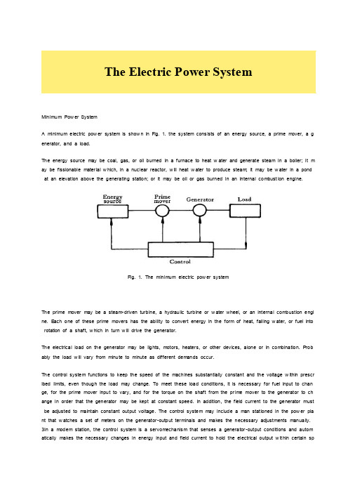
Minimum Pow er SystemA minimum electric pow er system is show n in Fig. 1. the system cons ists of an energy source, a prime mover, a g enerator, and a load.The energy source may be coal, gas, or oil burned in a furnace to heat w ater and generate steam in a boiler; it m ay be fissionable mater ial w hich, in a nuclear reactor, w ill heat w ater to produce steam; it may be w ater in a pond at an elevation above the generating station; or it may be oil or gas burned in an internal combust ion engine.Fig. 1. The minimum electric pow er systemThe prime mover may be a steam-driven turbine, a hydraulic turbine or w ater wheel, or an internal combustion engi ne. E ach one of these prime movers has the ability to convert energy in the form of heat, falling w ater, or fuel into rotation of a shaft, w hich in turn w ill drive the generator.The electrical load on the generator may be lights, motors, heaters, or other devices, alone or in combination. P rob ably the load w ill vary from minute to minute as different demands occur.The control system functions to keep the speed of the machines substantially constant and the voltage w ithin prescr ibed limits, even though the load may change. To meet these load conditions, it is necessary for fuel input to chan ge, for the prime mover input to vary, and for the torque on the shaft from the pr ime mover to the generator to ch ange in order that the generator may be kept at constant speed. In addition, the field current to the generator must be adjusted to maintain constant output voltage. The control system may include a man stationed in the pow er pla nt that w atches a set of meters on the generator-output ter minals and makes the necessary adjustments manually. 3In a modem station, the control system is a servomechanis m that senses a generator-output conditions and autom atically makes the necessary changes in energy input and field current to hold the electrical output w it hin certain specifications.More Complicated SystemsIn most situations the load is not directly connected to the generator ter minals. More commonly the load is some di stance from the generator, requir ing a pow er line connecting them. It is desirable to keep the electric pow er supply at the load w ithin specifications. How ever, the controls are near the generator, w hich may be in another building, p erhaps several miles aw ay.If the distance from the generator to the load is considerable, it may be desir able to install transformers at the gen erator and at the load end, and to trans mit the pow er over a high-voltage line (Fig. 2). For the same pow er, the hi gher-voltage line carries less current, has low er losses for the same w ire size, and provides more stable v oltage.In some cases an overhead line may be unacceptable. Instead it may be advantageous to use an under ground ca ble. With the pow er systems talked above, the pow er supply to the load must be interrupted if, for any reason, any component of the system must be removed from service for maintenance or repair..Fig 2A generators connected through transfor mers and a high-voltage line to a distant loadAdditional system load may requir e more pow er than the generator can supply. Another generator w ith its associate d transformers and high-voltage line might be added.It can be show n that there are some advantages in making ties betw een the generators (1) and at the ends of the high-voltage lines (2and 3), as show n in Fig. 3. This system w ill operate satisfactorily as long as no trouble develo ps or no equipment needs to be taken out of service.The above system may be vastly improved by the introduction of circuit br eakers, w hich may be opened and closed as needed. Circuit breakers added to the system, Fig. 4, per mit selected piece of equipment to sw itch out of servi ce w ithout disturbing the remainder of system. With this arrangement any element of the system may be r eenergize d for maintenance or repair by oper ation of circuit breakers. Of course, if any piece of equipment is taken out of s ervice, the total load must then carried by the remaining equipment. Attention must be given to avoid over loads dur i ng such circumstances. If possible, outages of equipment are scheduled at times w hen load requirements are below nor mal.Fig. 1-3 A system w ith parallel oper ation of the generators, of the transformers and of the trans mission linesFig. 4A system w ith necessary circuit breakersFig. 5Three generators supplying three loads over high-voltage trans mission linesFig. 5 show s a system in w hich three generators and three loads are tied together by three trans mission lines. No circuit breakers are show n in this diagram, although many w ould be required in such a system.Typical System LayoutThe gener ators, lines, and other equipment w hich form an electric system are arranged depending on the manner in w hich load grow s in the area and may be rearranged from time to time.Fig. 6 A radial pow er system supply ing several loadsHow ever, there are certain plans in to w hich a particular system des ign may be classified. Three types are illustrate d: the radial system, the loop system, and the netw ork system. All of these are show n w ithout the necessary circuit breakers. In each of these systems, a single generator serves four loads.The radial system is show n in Fig. 6. Here the lines form a “tree” spreading out from the generator. Opening any li ne results in interruption of pow er to one or more of the loads.The loop system is illustrated in Fig. 7. With this arrangement all loads may be served even though one line sectio n is removed from service. In some instances dur ing nor mal operation, the loop may be open at some point, such as A. In case a line section is to be taken out, the loop is first closed at A and then the line section removed. In this manner no service interruptions occur.Fig. 1-7A loop arrangement of lines for supplying several loadsFig. 8 show s the same loads being served by a netw ork. With this arrangement each load has tw o or more circuits over w hich it is fed.Distribution circuits are commonly des igned so that they may be classified as radial or loop circuits. The high-voltag e trans mission lines of most pow er systems are arranged as netw orks. The interconnection of major pow er systems results in netw orks made up many line sections.Fig. 8A netw ork of lines for supplying several loadsAuxiliary E quipmentCircuit breakers are necessary to deenergize equipment either for normal operation or on the occurrence of short ci rcuits. Circuit breakers must be designed to carry nor mal-load currents continuously, to w ithstand the extremely high currents that occur during faults, and to separate contacts and clear a circuit in the presence of fault. Circuit break ers are rated in ter ms of these duties.When a circuit breaker opens to deenergize a piece of equipment, one side of the circuit breaker usually rem ains e nergized, as it is connected to operating equipment. Since it is sometimes necessary to w ork on the circuit breaker itself, it is also necessary to have means by w hich the circuit breaker may be completely disconnected from other energized equipment. For this purpose disconnect sw itches are placed in series w ith the circuit breakers. By openin g these disconnests, the circuit breaker may be completely deenergized, per mitting w ork to be carried on in safety.Various instruments are necessary to monitor the operation of the electr ic pow er system. Usually each generator, ea ch transformer bank, and each line has its ow n set of instruments, frequently consisting of voltmeters, ammeters, w attmeters, and var meters.When a fault occurs on a system, conditions on the system undergo a sudden change. Voltages usually drop and currents increase. These changes are most noticeable in the immediate vicinity of fault. On-line analog computers, c ommonly called relays monitor these changes of conditions, make a deter minat ion of w hich breaker should be open ed to clear the fault, and energize the trip circuits of those appropriate breakers. 'With modern equipment, the relay action and breaker opening causes removal of fault w ithin three or four cycles after its initiation.The instruments that show circuit conditions and the relays that protect the circuits are not mounted directly on the pow er lines but are placed on sw itchboards in a control house. Instrument transformers are installed on the high-vol tage equipment, by means of which it is possible to pass on to the meters and relays representative samples of th e conditions on the operating equipment. The primary of a potential transformer is connected directly to the high-vol tage equipment. The secondary provides for the instruments and relays a voltage w hich is a constant fraction of vol tage on the operating equipment and is in phase w ith it. Similarly, a current transformer is connected w ith its primar y in the high-voltage circuit. The secondary w inding provides a current w hich is a know n fraction of the pow er-equip ment current and is in phase w ith it.Bushing potential devices and capac itor potential devices serve the same purpose as potential transformers but usually w ith less accuracy in regard to ratio and phase angle.Faults on Pow er SystemsFaults and its DamageEach year new designs of pow er equipment bring about increased reliability of operation. Nevertheless, equipment f ailures and interference by outside sources occasionally result in faults on electric pow er syst ems. On the occurrenc e of a fault, current and voltage conditions become abnor mal, the delivery of pow er from the generating stations to the loads may be unsatisfactory over a considerable area, and if the faulted equipment is not promptly disconnected from the remainder of the system, damage may result to other pieces of operating equipment.A fault is the unintentional or intentional connecting together of tw o or more conductors w hich ordinarily operate w it h a difference of potential betw een them. The connection betw een the conductors may be by physical metallic cont act or it may be through an arc. At the fault, the voltage betw een the tw o parts is reduced to zero in the case of metal-to-metal contacts, or to a very low value in case the connection is through an arc. Currents of abnor mally hig h magnitude flow through the netw ork to the point of fault. These short-circuit currents w ill usually be much greater than the designed ther mal ability of the conductors in the lines or machines feeding the fault. The resultant rise in t emperature may cause damage by the annealing of conductors and by the charring of insulation. In the period duri ng w hich the fault is per mitted to exist, the voltage on the system in the near vicinity of the fault w ill be so low th at utilization equipment w ill be inoperative. It is apparent that the pow er system designer must anticipate points at which faults may occur, be able to calculate conditions that exist during a fault, and provide equipment properly adj usted to open the sw itches necessary to disconnect the faulted equipment from the remainder of the system1. Ordi narily it is desirable that no other sw itches on the system are opened, as such behavior w ould result in unnecessar y modification of the system circuits.OverloadA distinction must be made betw een a fault and an overload. An overload implies only that loads greater than the designed values have been imposed on system. Under such a circumstance the voltage at the overload point may be low, but not zero. This under voltage condition may extend for some distance beyond the overload point into the remainder of the system. The currents in the overloaded equipment are high and may exceed the ther mal des ign l imits. Nevertheless, such currents are substantially low er than in the case of a fault. Service frequently may be mai ntained, but at below-standard voltage.Overloads are rather common occurrences in homes. For example, a housew ife might plug five w affle irons into the kitchen circuit during a neighborhood party. Such an overlo ad, if per mitted to continue, w ould cause heating of the w ires from the pow er center and might eventually start a fire. To prevent such trouble, residential circuits are prote cted by fuses or circuit breakers w hich open quickly w hen currents above specified values persist. Distribution transf or mers are sometimes overloaded as customers install more and more appliances. The continuous monitoring of dist ribution circuits is necessary to be certain that transfor mer sizes are increased as load grow s.Various FaultsFaults of many types and causes may appear on electric pow er systems. Many of us in our homes have seen fray ed lamp cords w hich permitted the tw o conductors of the cord to come in contact w ith each other. When this occur s, there is a resulting flash, and if breaker or fuse equipment functions properly, the circuit is opened.Overhead lines, for the most part, are constructed of bare conductors. These are sometimes accidentally brought to gether by action of w ind, sleet, trees, cranes, airplanes, or dama ge to supporting structures. Over voltages due to li ghtning or sw itching may cause flashover of supporting or from conductor to conductor. Contamination on insulators sometimes results in flashover even dur ing nor mal voltage conditions.The conductors of underground cables are separated from each other and from ground by solid insulation, w hich m ay be oil-impregnated paper or a plastic such as polyethylene. These materials undergo some deter ioration w ith ag e, particularly if overloads on the cables have resulted in their operation at elevated temperature. Any small void pr esent in the body of the insulating material w ill result in ionization of the gas contained therein, the products of w hi ch react unfavorably w ith the insulation, deterior ation of the insulation may result in failur e of the material to retain i ts insulating properties, and short circuits w ill develop betw een the cable conductors. The possibility of cable failure is increased if lightning or sw itching produces transient voltage of abnor mally high values betw een the conductors.Transfor mer failures may be the result of insulation deterioration combined w ith over-voltages due to lightning or sw i tching trans ients. Short circuits due to insulation failure betw een adjacent turns of the same w inding may result from suddenly applied over voltages. Major insulation may fail, per mitting arcs to be established betw een primary and se condary w indings or betw een a w inding and grounded metal part such as the core or tank.Generators may fail due to breakdow n of the insulation betw een adjacent turns in the same slot, resulting in a shor t circuit in a single turn of the generator. Insulation breakdow n may also occur betw een one of the w indings and th e grounded steel structure in w hich the coils are embedded. Breakdow n betw een different w indings lying in the sam e slot results in short-circuiting extensive sections of machine.Balanced three- phase faults, like balanced three-phase loads, may be handled on a line to-neutr al bas is or on an equivalent single-phase basis. P roblems may be solved either in ter ms of volts, amperes, and ohms. The handling of faults on single-phase lines is of course identical to the method of handling three-phase faults on an equivalent s ingle-phase basis.Per manent Faults and Temporary FaultsFaults may be classified as per manent or temporary. P er manent faults are those in w hich insulation failure or struct ure failure produces damage that makes operation of the equipment impossible and requires repairs to be made. T emporary faults are those w hich may be removed by deenergiz ing the equipment for a short period of time, short ci rcuits on overhead lines frequently are of this nature. High w inds may cause tw o or more conductors to sw ing toget her momentar ily. During the short period of contact, an arc is formed w hich may continue as long as the line remai ns energized. How ever i f automatic equipment can be brought into operation to deenergize the line quickly, little ph ysical damage may result and the line may be restored to service as soon as the are is extinguished. Arcs across insulators due to over voltages from lightning or sw itching trans ients usually can be cleared by automatic circuit-brea ker operation before significant structure damage occurs.Because of this characteristic of faults on lines, many companies operate follow ing a procedure know n as high-spee d reclosing. On the occurrence of a fault, the line is promptly deenergized by opening the circuit breakers at each end of the line. The breakers remain open long enough for the arc to clear, and then reclose automatically. In man y instances service is restored in a fraction of a second. Of course, if structure damage has occurred and the fault persists,it is necessary for the breakers to reopen and lock open.电力系统最低限度的电力系统最低电力系统显示图.1 .该系统包括能源,主要动力,一台发电机和负荷。
(完整版)电力系统外文英语文献资料
Electric Power SystemElectrical power system refers to remove power and electric parts of the part,It includes substation, power station and distribution. The role of the power grid is connected power plants and users and with the minimum transmission and distribution network disturbance through transport power, with the highest efficiency and possibility will voltage and frequency of the power transmission to the user fixed .Grid can be divided into several levels based on the operating voltage transmission system, substructure, transmission system and distribution system, the highest level of voltage transmission system is ZhuWangJia or considered the high power grids. From the two aspects of function and operation, power can be roughly divided into two parts, the transmission system and substation. The farthest from the maximum output power and the power of the highest voltage grade usually through line to load. Secondary transmission usually refers to the transmission and distribution system is that part of the middle. If a plant is located in or near the load, it might have no power. It will be direct access to secondary transmission and distribution system. Secondary transmission system voltage grade transmission and distribution system between voltage level. Some systems only single second transmission voltage, but usually more than one. Distribution system is part of the power system and its retail service to users, commercial users and residents of some small industrial users. It is to maintain and in the correct voltage power to users responsible. In most of the system, Distribution system accounts for 35% of the total investment system President to 45%, and total loss of system of the half .More than 220kv voltage are usually referred to as Ultra high pressure, over 800kv called high pressure, ultra high voltage and high pressure have important advantages, For example, each route high capacity, reduce the power needed for the number of transmission. In as high voltage to transmission in order to save a conductor material seem desirable, however, must be aware that high voltage transmission can lead to transformer, switch equipment and other instruments of spending increases, so, for the voltage transmission to have certain restriction, allows it to specific circumstances in economic use. Although at present, power transmission most is through the exchange of HVDC transmission, and the growing interest in, mercury arc rectifier and brake flow pipe into the ac power generation and distribution that change for the high voltage dc transmission possible.Compared with the high-voltage dc high-voltage ac transmission has the following some advantages: (1) the communication with high energy; (2) substation of simple maintenance and communication cost is low; (3) ac voltage can easily and effectively raise or lower, it makes the power transmission and high pressure With safety voltage distributionHVDC transmission and high-voltage ac transmission has the following advantages: (1) it only need two phase conductors and ac transmission to three-phase conductors; (2) in the dc transmission impedance, no RongKang, phase shift and impact overvoltage; (3) due to the same load impedance, no dc voltage, and transfer of the transmission line voltage drop less communication lines, and for this reason dc transmission line voltage regulator has better properties; (4) in dc system without skin effect. Therefore, the entire section of route conductors are using; (5) for the same work, dc voltage potential stress than insulation. Therefore dc Wire need less insulation; (6) dc transmission line loss, corona to little interference lines of communication; (7) HVDC transmission without loss of dielectric, especially in cable transmission; (8) in dc system without stability and synchronization of trouble.A transmission and the second transmission lines terminated in substation or distribution substations, the substation and distribution substations, the equipment including power and instrument transformer and lightning arrester, with circuit breaker, isolating switch, capacitor set, bus and a substation control equipment, with relays for the control room of the equipment. Some of the equipment may include more transformer substations and some less, depending on their role in the operation. Some of the substation is manual and other is automatic. Power distribution system through the distribution substations. Some of them by many large capacity transformer feeders, large area to other minor power transformer capacity, only a near load control, sometimes only a doubly-fed wire feeders (single single variable substation)Now for economic concerns, three-phase three-wire type communication network is widely used, however, the power distribution, four lines using three-phase ac networks.Coal-fired power means of main power generating drive generators, if coal energy is used to produce is pushing the impeller, then generate steam force is called the fire. Use coal produces steam to promote the rotating impeller machine plant called coal-fired power plants. In the combustion process, the energy stored in the coal to heat released,then the energy can be transformed into the form within vapor. Steam into the impeller machine work transformed into electrical energy.Coal-fired power plants could fuel coal, oil and natural gas is. In coal-fired power plant, coal and coal into small pieces first through the break fast, and then put out. The coal conveyer from coal unloader point to crush, then break from coal, coal room to pile and thence to power. In most installations, according to the needs of coal is, Smash the coal storage place, no coal is through the adjustable coal to supply coal, the broken pieces of coal is according to the load changes to control needs. Through the broken into the chamber, the coal dust was in the second wind need enough air to ensure coal burning.In function, impeller machine is used to high temperature and high pressure steam energy into kinetic energy through the rotation, spin and convert electricity generator. Steam through and through a series of impeller machine parts, each of which consists of a set of stable blade, called the pipe mouth parts, even in the rotor blades of mobile Li called. In the mouth parts (channel by tube nozzle, the steam is accelerating formation) to high speed, and the fight in Li kinetic energy is transformed into the shaft. In fact, most of the steam generator is used for air is, there is spread into depression, steam turbine of low-pressure steam from the coagulation turbine, steam into the condenses into water, and finally the condensate water is to implement and circulation.In order to continuous cycle, these must be uninterrupted supply: (1) fuel; (2) the air (oxygen) to the fuel gas burning in the configuration is a must; (3) and condenser, condensed from the condensed water supply, sea and river to lake. Common cooling tower; (4) since water vapour in some places in circulation, will damage process of plenty Clean the supply.The steam power plant auxiliary system is running. For a thermal power plant, the main auxiliary system including water system, burning gas and exhaust systems, condensation system and fuel system. The main auxiliary system running in the water pump, condensation and booster pump, coal-fired power plants in the mill equipment. Other power plant auxiliary equipment including air compressors, water and cooling water system, lighting and heating systems, coal processing system. Auxiliary equipment operation is driven by motor, use some big output by mechanical drive pump and some of the impeller blades, machine drive out from the main use of water vaporimpeller machine. In coal-fired power plant auxiliary equipment, water supply pump and induced draft fan is the biggest need horsepower.Most of the auxiliary power generating unit volume increased significantly in recent years, the reason is required to reduce environment pollution equipment. Air quality control equipment, such as electrostatic precipitator, dust collection of flue gas desulfurization, often used in dust in the new coal-fired power plants, and in many already built in power plant, the natural drive or mechanical drive, fountain, cooling tower in a lake or cooling canal has been applied in coal-fired power plants and plants, where the heat release need to assist cooling system.In coal-fired power stations, some device is used to increase the thermal energy, they are (1) economizer and air preheater, they can reduce the heat loss; (2) water heater, he can increase the temperature of water into boiling water heaters; (3) they can increase and filter the thermal impeller.Coal-fired power plants usually requires a lot of coal and coal reservoirs, however the fuel system in power plant fuel handling equipment is very simple, and almost no fuel oil plants.The gas turbine power plants use gas turbine, where work is burning gas fluid. Although the gas turbine must burn more expensive oil or gas, but their low cost and time is short, and can quickly start, they are very applicable load power plant. The gas turbine burn gas can achieve 538 degrees Celsius in the condensing turbine, however, the temperature is lower, if gas turbine and condenser machine, can produce high thermal efficiency. In gas turbine turbine a combined cycle power plant. The gas through a gas turbine, steam generator heat recovery in there were used to generate vapor heat consumption. Water vapor and then through a heated turbine. Usually a steam turbine, and one to four gas turbine power plant, it must be rated output power.。
电力专业英语英文文献翻译报告

电力专业英语英文文献翻译报告Page 1.The Production of Electrical Energy(电能生产)1 English textFrom reference 1Should the generation be not adequate to balance the load demand, it is imperative that one of following alternatives be considered for keeping the system in operating condition:1. Staring fast peaking units,2. Load shedding for unimportant loads,3. generation rescheduling.It is apparent from the above that since the voltage specifications are not stringent, load frequency control is by far the most important in power system control.In order to understand the frequency control, consider a small step-increase in load. The initial distribution of the load increment is determined by the system simpedance; and the sistantaneous relative generator rotor positions. The energy required to supply the load increment is drawn from the kinetic energy of rotating machines. As a result, the system frequency drops. The distribution of load during this period among the various machines is determined by the inertias of the rotors of the generators partaking in process. This problem is stability analysis of the system.After the speed or frequency fall due to reduction in stored energy in the rotors has taken place, the drop is sensed by the governors and they divide the load increment between the machines as determined by the droops of the respective governor characterstics. Subsequently, secondary control restores the system frequency to its normal value by readjustingthe governor characteristics. Keywords:load frequency control From reference 2Modern power systems are so large that it is impossible to design a single central control system that would handle the overall control job. It is extremely useful take into account the weak links in the system and then apply control through decomposition. The demarcation of load frequency control and Mavar voltage control characteristics is one such decomposition. Geographical and functional decomposition are successfully applied to power systems and this leads to the concept of area control.A modern power system can be divided into several areas for load frequency control. Each control area fulfils the following:1.The area is a geographically contious portion of a large interconnected area, which adjusts its own generation to accommodate load changes within its precincts.2.Under normal conditions of operation, it changes bulk power with neighboring areas.3.Under abnormal conditions of operation, it may deviate from predetermined schedules and provide assistance to any neighboring control area in the system.4.It is expected, in addition, to partake with the other areas in the system in a suitable manner in the system frequency regulation.The rotors of all generators in a control area swing together for load change. Thus, a coherent group of generators within a geographical region may constitute a control area which is connected to other similar areas by weak tie lines.Keywords:areas load frequency controlFrom reference 3For plant loading schedules in thermal systems, load prediction up to two hours in advance is necessary while for unit commitment schedules prediction up to 24 hours is sufficient. Also, at all sations and control centers, short-time prediction is needed for storage and display of advance information. Based on this information, predictive security assessment of the system is made. This also helps to contain the rates of change of generator outputs within their permissible limits.For the implementation of economic scheduling of generation using digital computers, detailed estimates of the future load demands are essential in order to allow sufficient time for the calculation and implementation of the generator schedules. Whatever method is envisaged for the calculation of such economic schedules consistent with the security and spare requirements of the system, the schedules should be calculated every 15 or 30 minutes and each economic schedule should be a predictive one ,for at least about 30 minutes ahead of event. It is then obvious that the predictions are to be revised frequently in the light of any fresh information so as to minimize the estimation errors.Peak load demand forecasts are useful in determining the investment required for additional generating and transmission capacities required. Forecasts for planning require data extending over several previous years. Meaningful forecasts can be obtained with lead time of 3 to 5 years.Keywords:load predictionFrom reference 4In this method, the load is separated into two main components. The first component is a base load which is of fixed value and the second a variable component which is a functionof the weather conditions.Estimates can be made 24 hours ahead, using the weather forecast. The temperature base for weighting the effect of the predicated temperature on the load is the normal, mean temperature of the month. The normal, mean temperature of the month has zero weight. Similarly the change in consumers demand due to cloudy weather may be assumed to vary in direct proportion to the degree of cloudiness. This in turn may be expressed by an illumination index with fair, clear sky corresponding to zero weight.The base load is determined from past records. Proper weighting of the elements of the weather will be attained only after several trials. The method of prediction stabilizes after this trial period. It may be noted that the base loads for week days and weekend will generally be different for any hour.Using these base loads, a load estimate based on the best available weather forecast can be made using proper weighting of meteorological factors like temperature, cloudiness, wind velocity, etc.Keywords:proper weighting of the elements of the weather2 中文翻译及分析出自文献1:万一发电量不足以平衡负荷需求,要使电力系统处于运行状态,必须考虑采取以下选择方法中的一种:1、启动快速峰荷机组2、对不重要的用户实行拉闸断电3、重新制定发电计划从上述情况来看,电压技术的要求并不严格,目前为止负荷频率控制是电力系统控制中最重要的手段。
(完整版)电力系统外文英语文献资料

(完整版)电力系统外文英语文献资料Electric Power SystemElectrical power system refers to remove power and electric parts of the part,It includes substation, power station and distribution. The role of the power grid is connected power plants and users and with the minimum transmission and distribution network disturbance through transport power, with the highest efficiency and possibility will voltage and frequency of the power transmission to the user fixed .Grid can be divided into several levels based on the operating voltage transmission system, substructure, transmission system and distribution system, the highest level of voltage transmission system is ZhuWangJia or considered the high power grids. From the two aspects of function and operation, power can be roughly divided into two parts, the transmission system and substation. The farthest from the maximum output power and the power of the highest voltage grade usually through line to load. Secondary transmission usually refers to the transmission and distribution system is that part of the middle. If a plant is located in or near the load, it might have no power. It will be direct access to secondary transmission and distribution system. Secondary transmission system voltage grade transmission and distribution system between voltage level. Some systems only single second transmission voltage, but usually more than one. Distribution system is part of the power system and its retail service to users, commercial users and residents of some small industrial users. It is to maintain and in the correct voltage power to users responsible. In most of the system, Distribution system accounts for 35% of the total investment system President to 45%, andtotal loss of system of the half .More than 220kv voltage are usually referred to as Ultra high pressure, over 800kv called high pressure, ultra high voltage and high pressure have important advantages, For example, each route high capacity, reduce the power needed for the number of transmission. In as high voltage to transmission in order to save a conductor material seem desirable, however, must be aware that high voltage transmission can lead to transformer, switch equipment and other instruments of spending increases, so, for the voltage transmission to have certain restriction, allows it to specific circumstances in economic use. Although at present, power transmission most is through the exchange of HVDC transmission, and the growing interest in, mercury arc rectifier and brake flow pipe into the ac power generation and distribution that change for the high voltage dc transmission possible.Compared with the high-voltage dc high-voltage ac transmission has the following some advantages: (1) the communication with high energy; (2) substation of simple maintenance and communication cost is low; (3) ac voltage can easily and effectively raise or lower, it makes the power transmission and high pressure With safety voltage distribution HVDC transmission and high-voltage ac transmission has the following advantages: (1) it only need two phase conductors and ac transmission to three-phase conductors; (2) in the dc transmission impedance, no RongKang, phase shift and impact overvoltage; (3) due to the same load impedance, no dc voltage, and transfer of the transmission line voltage drop less communication lines, and for this reason dc transmission line voltage regulator has better properties; (4) in dc system withoutskin effect. Therefore, the entire section of route conductors are using; (5) for the same work, dc voltage potential stress than insulation. Therefore dc Wire need less insulation; (6) dc transmission line loss, corona to little interference lines of communication; (7) HVDC transmission without loss of dielectric, especially in cable transmission; (8) in dc system without stability and synchronization of trouble.A transmission and the second transmission lines terminated in substation or distribution substations, the substation and distribution substations, the equipment including power and instrument transformer and lightning arrester, with circuit breaker, isolating switch, capacitor set, bus and a substation control equipment, with relays for the control room of the equipment. Some of the equipment may include more transformer substations and some less, depending on their role in the operation. Some of the substation is manual and other is automatic. Power distribution system through the distribution substations. Some of them by many large capacity transformer feeders, large area to other minor power transformer capacity, only a near load control, sometimes only a doubly-fed wire feeders (single single variable substation)Now for economic concerns, three-phase three-wire type communication network is widely used, however, the power distribution, four lines using three-phase ac networks.Coal-fired power means of main power generating drive generators, if coal energy is used to produce is pushing the impeller, then generate steam force is called the fire. Use coal produces steam to promote the rotating impeller machine plant called coal-fired power plants. In the combustion process, the energy stored in the coal to heat released,then the energy can be transformed into the form within vapor. Steam into the impeller machine work transformed into electrical energy.Coal-fired power plants could fuel coal, oil and natural gas is. In coal-fired power plant, coal and coal into small pieces first through the break fast, and then put out. The coal conveyer from coal unloader point to crush, then break from coal, coal room to pile and thence to power. In most installations, according to the needs of coal is, Smash the coal storage place, no coal is through the adjustable coal to supply coal, the broken pieces of coal is according to the load changes to control needs. Through the broken into the chamber, the coal dust was in the second wind need enough air to ensure coal burning.In function, impeller machine is used to high temperature and high pressure steam energy into kinetic energy through the rotation, spin and convert electricity generator. Steam through and through a series of impeller machine parts, each of which consists of a set of stable blade, called the pipe mouth parts, even in the rotor blades of mobile Li called. In the mouth parts (channel by tube nozzle, the steam is accelerating formation) to high speed, and the fight in Li kinetic energy is transformed into the shaft. In fact, most of the steam generator is used for air is, there is spread into depression, steam turbine of low-pressure steam from the coagulation turbine, steam into the condenses into water, and finally the condensate water is to implement and circulation.In order to continuous cycle, these must be uninterrupted supply: (1) fuel; (2) the air (oxygen) to the fuel gas burning in the configuration is a must; (3) and condenser, condensed from the condensed water supply, sea and river to lake. Common coolingtower; (4) since water vapour in some places in circulation, will damage process of plenty Clean the supply.The steam power plant auxiliary system is running. For a thermal power plant, the main auxiliary system including water system, burning gas and exhaust systems, condensation system and fuel system. The main auxiliary system running in the water pump, condensation and booster pump, coal-fired power plants in the mill equipment. Other power plant auxiliary equipment including air compressors, water and cooling water system, lighting and heating systems, coal processing system. Auxiliary equipment operation is driven by motor, use some big output by mechanical drive pump and some of the impeller blades, machine drive out from the main use of water vaporimpeller machine. In coal-fired power plant auxiliary equipment, water supply pump and induced draft fan is the biggest need horsepower.Most of the auxiliary power generating unit volume increased significantly in recent years, the reason is required to reduce environment pollution equipment. Air quality control equipment, such as electrostatic precipitator, dust collection of flue gas desulfurization, often used in dust in the new coal-fired power plants, and in many already built in power plant, the natural drive or mechanical drive, fountain, cooling tower in a lake or cooling canal has been applied in coal-fired power plants and plants, where the heat release need to assist cooling system.In coal-fired power stations, some device is used to increase the thermal energy, they are (1) economizer and air preheater, they can reduce the heat loss; (2) water heater, he can increase the temperature of water into boiling water heaters; (3) they can increase and filter the thermal impeller.Coal-fired power plants usually requires a lot of coal and coal reservoirs, however the fuel system in power plant fuel handling equipment is very simple, and almost no fuel oil plants.The gas turbine power plants use gas turbine, where work is burning gas fluid. Although the gas turbine must burn more expensive oil or gas, but their low cost and time is short, and can quickly start, they are very applicable load power plant. The gas turbine burn gas can achieve 538 degrees Celsius in the condensing turbine, however, the temperature is lower, if gas turbine and condenser machine, can produce high thermal efficiency. In gas turbine turbine a combined cycle power plant. The gas through a gas turbine, steam generator heat recovery in there were used to generate vapor heat consumption. Water vapor and then through a heated turbine. Usually a steam turbine, and one to four gas turbine power plant, it must be rated output power.。
- 1、下载文档前请自行甄别文档内容的完整性,平台不提供额外的编辑、内容补充、找答案等附加服务。
- 2、"仅部分预览"的文档,不可在线预览部分如存在完整性等问题,可反馈申请退款(可完整预览的文档不适用该条件!)。
- 3、如文档侵犯您的权益,请联系客服反馈,我们会尽快为您处理(人工客服工作时间:9:00-18:30)。
中英文资料外文翻译Faults on Power SystemsEach year new design of power equipment bring about increased reliability of operation. Nevertheless, equipment failures and interference by outside sources occasionally result in faults on electric power systems. On the occurrence of a fault , current an voltage conditions become abnormal, the delivery of power from the generating station to the loads may be unsatisfactory over a considerable area, and if the faulted equipment is not promptly disconnected from the remainder of the system, damage may result to other pieces of operating equipment.A faulty is the unintentional or intentional connecting together of two or more conductors which ordinarily operate with a difference of potential between them. The connection between the conductors may be by physical metallic contact or it may be through an arc. At the fault, the voltage between the two parts is reduced to zero in the case of metal-to-metal contacts, or to a very low value in case the connection is through an arc. Currents of abnormally high magnitudeflow through the network to the point of fault. These short-circuit currents will usually be much greater than the designed thermal ability of the condition in the lines or machines feeding the fault . The resultant rise in temperature may cause damage by the annealing of conductors and by the charring of insulation. In the period during which the fault is permitted to exist, the voltage on the system in the near vicinity of the fault will be so low that utilization equipment will be inoperative. It is apparent that the late conditions that exist during a fault, and provide equipment properly adjusted to open the switches necessary to disconnect the faulted equipment from the remanding of the system. Ordinarily it is desirable that no other switches on the system are opened, as such behavior would result in unnecessary modification the system circuits.A distinction must be made between and an overload. An overload implies only that loads greater than the designed values have been imposed on system. Under such a circumstance the voltage at the overload point may be low, but not zero. This undervoltage condition may extend for some distance beyond the overload point into the remainder of the system. The current in the overload equipment are high and may exceed the thermal design limits. Nevertheless, such currents are substantially lower than in the case of a fault. Service frequently may be maintained, but at below-standard voltage.Overloads are rather common occurrences in homes. For example, a housewife might plug five waffle irons into the kitchen circuit during a neighborhood part. Such an overload, if permitted to continue,would cause heating of the wires from the power center and might eventually start a fire. To prevent such trouble, residential circuits are protected by fuses or circuit breakers which open quickly when currents above specified values persist. Distribution transformers are sometimes overloads as customers install more and more appliances. The continuous monitoring of distribution circuits is necessary to be certain that transformers sizes are increased as load grows.Faults of many types and causes may appear on electric power systems. Many of us in our homes have seen frayed lamp cords which permitted the two conductors of the cord to come in contact with each other. When this occurs, there is a resulting flash, and if breaker or fuse equipment functions properly, the circuit is opened.Overhead lines, for the most part, are constructed of bare conductors. There are sometimes accidentally brought together by action of wind, sleets, trees, cranes, airplanes, or damage to supporting structures. Overvoltages due to lighting or switching nay cause flashover of supporting or from conductor to conductor. Contamination on insulators sometimes results in flashover even during normal voltage conditions.The conductors of underground cables are separated from each and from ground by solid insulation, which nay be oil-impregnated paper or a plastic such polyethylene. These materials undergo some deterioration with age, particularly if overloads on the cables have resulted in their operation at elevated temperature. Any small void present in the body of the insulating material will results in ionizationof the gas contained therein, the products of which react unfavorably with the insulation. Deterioration of the insulation may result in failure of the material to retain its insulating properties, and short circuits will develop between the cable conductors. The possibility of cable failure is increased if lightening or switching produces transient voltage of abnormally high values between the conductors.Transformer failures may be the result of insulation deterioration combined with overvoltage due to lightning or switching transients. Short circuit due to insulation failure between adjacent turns of the same winding may result from suddenly applied overvoltage. Major insulation may fail, permitting arcs to be established between primary and secondary windings or between winding and grounded metal parts such as the core or tank.Generators may fail due to breakdown of the insulation between adjacent turns in the same slot, resulting in a short circuit in a single turn of the generator. Insulation breakdown may also occur between one of the winding and the grounded steel structure in which the coils are embedded. Breakdown between different windings lying in the same slot results in short-circuiting extensive section of machine.Balanced three-phase faults, like balanced three-phase loads, may be handled on a lineto-neutral basis or on an equivalent single-phase basis. Problems may be solved either in terms of volts, amperes, and ohms. The handing of faults on single-phase lines is of course identical to the method of handing three-phase faults on an equivalent single-phase basis.Faults may be classified as permanent or temporary. Permanent faults are those in which insulation failure or structure failure produces damage that makes operation of the equipment impossible and requires repairs to be made. Temporary faults are those which may be removed by deenergizing the equipment for a short period of time, short circuits on overhead lines frequently are of this nature. High winds may cause two or more conductions to swing together momentarily. During the short period of contact. An arc is formed which may continue as long as line remains energized. However, if automatic equipment can be brought into operation to service as soon as the are is extinguished. Arcs across insulators due to overvoltages from lighting or switching transients usually can be cleared by automatic circuit-breaker operation before significant structure damage occurs.Because of this characteristic of faults on lines, many companies operate following a procedure known as high-speed reclosing. On the occurrence of a fault, the line is promptly deenergized by opening the circuit breakers at each end of the line. The breakers remain open long enough for the arc to clear, and then reclose automatically. In many instances service is restored in a fraction of a second. Of course, if structure damage has occurred and the fault persists, it is necessary for the breakers to reopen and lock open.电力系统故障每年新设计的电力设备都使系统的可靠性不断提高,然而,设备的使用不当以及一些偶然遇到的外在因素均会导致系统故障的发生。