ATmega128程序烧写说明书
ATMEGA128--AVR教程
AVR教程(1):AVR单片机介绍作者:微雪电子文章来源: 点击数: 478 更新时间:2008-4-1 23:58:21 AVR,它来源于:1997年,由ATMEL公司挪威设计中心的A先生与V先生利用ATMEL公司的Flash新技术,共同研发出RISC精简指令集的高速8位单片机,简称AVR。
AVR单片机特点每种MCU都有自身的优点与缺点,与其它8-bit MCU相比,AVR 8-bit MCU最大的特点是:●哈佛结构,具备1MIPS / MHz的高速运行处理能力;●超功能精简指令集(RISC),具有32个通用工作寄存器,克服了如8051 MCU采用单一ACC 进行处理造成的瓶颈现象;●快速的存取寄存器组、单周期指令系统,大大优化了目标代码的大小、执行效率,部分型号FLASH非常大,特别适用于使用高级语言进行开发;●作输出时与PIC的HI/LOW相同,可输出40mA(单一输出),作输入时可设置为三态高阻抗输入或带上拉电阻输入,具备10mA-20mA灌电流的能力;●片内集成多种频率的RC振荡器、上电自动复位、看门狗、启动延时等功能,外围电路更加简单,系统更加稳定可靠;●大部分AVR片上资源丰富:带E2PROM,PWM,RTC,SPI,UART,TWI,ISP,AD,Analog Comp arator,WDT等;●大部分AVR除了有ISP功能外,还有IAP功能,方便升级或销毁应用程序。
●性价比高。
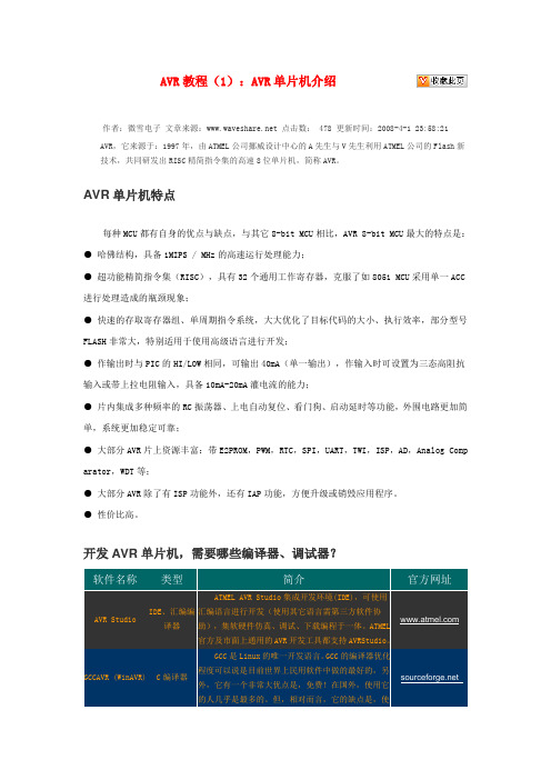
开发AVR单片机,需要哪些编译器、调试器?软件名称类型简介官方网址AVR Studio IDE、汇编编译器ATMEL AVR Studio集成开发环境(IDE),可使用汇编语言进行开发(使用其它语言需第三方软件协助),集软硬件仿真、调试、下载编程于一体。
ATMEL官方及市面上通用的AVR开发工具都支持AVRStudio。
GCCAVR (WinAVR) C编译器GCC是Linux的唯一开发语言。
GCC的编译器优化程度可以说是目前世界上民用软件中做的最好的,另外,它有一个非常大优点是,免费!在国外,使用它的人几乎是最多的。
Atmega128开发板使用说明书
Atmega128开发板使用说明书概要介绍Atmega128开发板上硬件资源丰富,接口齐全,基本上涵盖了Atmega128单片机所能涉及到的所有功能,可以满足单片机开发工程师和电子爱好者的开发实验的需求,或者高校电子、计算机专业学生的学习实验的需要。
按照正规产品的要求设计,不纯粹是实验样品,器件选型、原理图、PCB设计的时候都充分考虑了可靠稳定性。
Atmega128的IO口资源丰富,板上所以接口都是独立使用的,不需要任何跳线进行设置, IO口外围扩展使用了2片锁存器74HC574,既可以使实验变得更加简单方便,又能让实验者掌握更多的单片机设计知识。
提供配套软件源代码,学习板的每个实验都有与其相对应的软件代码,是版主从多年的工作经验中提取出来的,并经过优化,具有较高的参考价值。
编程简单,学习板编程不需要专用烧录器,利用计算机的并口即可进行编程,速度快、操作简单。
1.产品清单Atmega128开发板的配件清单如下,当您第一次拿到产品的时候,请参照下图认真核对包装内配件是否齐全,以及各配件是否完好无损。
请按照下图安装122*32 LCD,lCD的一脚对准122*32 LCD插座的一脚,切记不要插反2.硬件布局说明步进电机接口直流电机接口数字温度传感器SD卡插座光敏电阻ADC输入电位器NTC热敏电阻JTAG接口继电器接口9V电源输入接口DAC输出接口RS485接口RS232接口红外发射管ISP编程接口LCD对比度调节电位器122 * 32点阵LCD接口16 * 2字符LCD接口红外接收管433M射频模块接口3 *4 矩阵键盘3.接口说明接口管脚顺序的确认方法●对于有卡口的接口,应对着卡口的方向看,最左边为第一个管脚,如下图所示:●对于用螺丝压线的接口,应对着入线的方向看,最左边为第一个管脚,如下图所示:特别提示:ISP下载接口与JTAG接口封装相同,下载程序时使用ISP接口,不要插到JTAG 接口上4.硬件开发环境的建立本站出售的AVR单片机学习板就是一套完整的硬件环境,它由学习板、电源、并口ISP 下载线等组成。
Atmega128PWM程序
key_yanshi();
break;
//按键 5:PWM1B 正脉宽减小
case 6:
OCR0-=8;
key_yanshi();
break; //按键 6:PWM2 正脉宽减小
case 7:break;
//按键 7
case 8:break;
//按键 8
case 9:break;
//按键 9
case 10:break;
TCNT3=0x0000;
//清零计数器
}
/*******************************************************/
/****** 函数名称: Pwm2_Init()
******/
/****** 功 能: Pwm2 初始化函数
******/
/****** 参 数: 无
//按键 A
case 11:break;
//按键 B
case 12:break;
//按键 C
case 13:break;
//按键 D
case 14:break;
//按键 E
case 15:break;
//按键 F
default:break;
}
}
}
}
//快速 PWM,时钟 1024 分频
OCR0=0x20;
//正脉宽
TCNT0=0x00;
//清零计数器
}
/*******************************************************/
/****** 函数名称: main()
******/
/****** 功 能: 三路 PWM 同时输出
ATmega128开发板功能说明
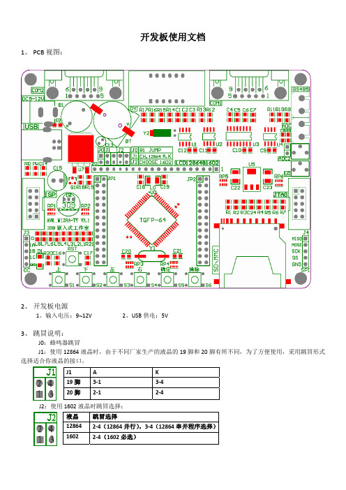
开发板使用文档1、 PCB 视图:2、 开发板电源1、输入电压:9~12V2、USB 供电:5V3、 跳冒说明:J0:蜂鸣器跳冒J1:使用12864液晶时,由于不同厂家生产的液晶的19脚和20脚有所不同,为了方便使用,采用跳冒形式选择适合你液晶的接口,J2:使用1602液晶时跳冒选择:J1 A K 19脚 3‐1 3‐4 20脚2‐12‐4液晶 跳冒选择12864 2‐4(12864并行),3‐4(12864串并程序选择)16022‐4(1602必选)3、功能说明:1、温度传感器18B202、两通道ADC3、4位数码管显示4、实时时钟DS13025、串口0,串口16、SD卡读写7、IIC_24C02(TWI)8、RS485通讯9、LCD12864接口10、LCD1602接口11、6个按键(有上,下,左,右,确定,取消)12、跑马灯13、SPI14、JTAG接口15、ISP接口16、蜂蜜器17、USB供电18、I/O口扩展4、实验例程:1、跑马灯2、数码管显示3、蜂鸣器4、定时器0输出方波5、定时器2中断6、外部中断7、串口实验 8、RS4859、AT24C02 10、按键实验11、1602液晶显示 12、12864液晶显示13、ADC数码管显示实验 14、ADC在12864液晶显示15、DS18B20数码管显示 16、DS18B20液晶1620显示17、DS18B20液晶LCD12864显示 18、DS1302实时时钟1602显示19、DS1302实时时钟LCD12864显示 20、DS18B20实时时钟液晶显示21、串口多机通讯 22、RS485多机通讯23、SD卡读写 24、SPI通讯25、μCOS-II在ATmega128开发板上的移植。
ATMEGA128熔丝位配置手册.wps

1、打钩的表明用到的功能
2、0表示允许,1表示禁止
3、BODLEVEL = 1 掉电检测2.7V 0 为4V
4、BODEN = 1 掉电检测失效,这和BODLEVEL配合使用
5、A VR芯片加密以后仅仅是不能读取Flash和E2PROM的内容,也不能重新下载进去,下载完了以后要给芯片加密,再想往里头灌程序就灌不进去了。
必须先擦除后再重新灌进去。
6、SPIEN = 0 表示允许使用SPI口下载
7、JTAGEN = 0 表示允许使用JTAG口下载
8、一般情况下不要把RESET定义成普通的I/O口,因为ISP 下载时要先拉低是芯片先进入复位状态。
9、M103C = 1 和ATMEGA103不兼容的方式运行,ATMEGA128的方式运行
10、SUT 1:0 = 1 0 以最长的延时方式启动
11、CLKSEL 3:1 = 1111以外部高频石英晶振3-8MHz或8MHz 以上,CLKSEL 3:0 = 0001 内部1MHz的RC振荡JTAGEN = 1 禁止JTAG口
12、WDTON = 1 禁止看门狗
13、EESAVE = 1 执行擦除命令时连同EEPROM的内容同FLASH的内容一同擦除
14、BOOTRST = 1 程序执行时从地址0x0000开始执行
BOOTRST = 0 程序执行时从地址BOOTLOAD起始地
址区开始执行
15、BOOTSZ1和BOOTSZ0决定了BOOTLOAD的大小和起
地址,默认为00 大小为4096字,起始地址为0xF000
16、LB 2:1 = 11 没有使能存储器使能保护功能
17、BLB02 : BLB01 = 11
18、BLB12 : BLB11 = 11。
使用AVR Studio烧写程序
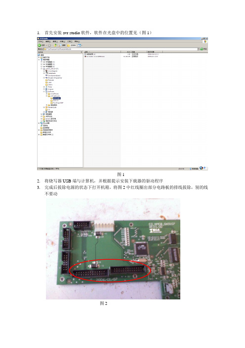
2.将烧写器USB端与计算机,并根据提示安装下载器的驱动程序
3.完成后拔除电源的状态下打开机箱,将图2中红线圈出部分电路板的排线拔除,别的线不要动
图2
4.将烧写器另一头插于电路板图3红线圈出位置
图3
5.以上步骤完成后打开设备电源,打开AVR Studio软件,出现图4所示,点击Cancel,
图4
图8-2(ATmega2561熔丝位,注意区分芯片型号并在“main”中选择型号)
5.根据图9所示正确设置并选择所要烧写的程序,最后点击Program
图9
6.点击图5中圈出位置,设置端口,端口具体设置见图6,端口号可以在设备管理器里查看,设置完后点击connect
图5
图6
5.点击connect,然后进入Program选项卡
图7
熔丝位,如图8所示进行勾选,并点击program
图8-1(ATmega128熔丝位)
点击connect后会跳出图所示对话框选择图中圈出位置不要点击旁边按键然后进入program选项卡熔丝位如图8所示进行勾选并点击program图81atmega128图82atmega2561熔丝位注意区分芯片型号并在main中选择型号根据图9所示正确设置并选择所要烧写的程序最后点击program
1.首先安装avr studio软件,软件在光盘中的位置见(图1)
ATmega128串口通信程序(中断方式)
ATmega128串口通信程序(中断方式)2011-06-05 20:08:10| 分类:单片机程序编写| 标签:|字号大中小订阅程序采用IAR系统编译,实现使用串口调试助手收发数据的功能#include<iom128.h>#include<inavr.h>#include<string.h>#define INT8U unsigned char#define INT16U unsigned int#define UDRIE0 5/* UART Buffer Defines */#define UART0_RX_BUFFER_SIZE 128#define UART0_TX_BUFFER_SIZE 128/* Static Variables */static unsigned char UART0_RxBuf[UART0_RX_BUFFER_SIZE];static volatile unsigned char UART0_RxHead;static volatile unsigned char UART0_RxTail;static unsigned char UART0_TxBuf[UART0_TX_BUFFER_SIZE];static volatile unsigned char UART0_TxHead;static volatile unsigned char UART0_TxTail;static unsigned char UART0_Flag=1;void USART_INIT( void ){UBRR0H = 0x00;UBRR0L = 0x0B;//9600 at 1.8432MUCSR0A = 0x20;UCSR0B = 0xD8;//开接收结束中断,发送结束中断接收使能,发送使能UCSR0C = 0x06;//异步模式,1位停止位,8位数据位UDR0 = 0x00;//清空数据寄存器UART0_RxTail = 0;UART0_RxHead = 0;UART0_TxTail = 0;UART0_TxHead = 0;__disable_interrupt();//关全局中断}void Tran_Byte( INT8U sdata ){if(UART0_Flag == 0){UDR0 = sdata;UART0_Flag = 1;}else{UART0_TxBuf[UART0_TxHead] = sdata;UART0_TxHead++;if(UART0_TxHead >= UART0_TX_BUFFER_SIZE) UART0_TxHead = 0; }__enable_interrupt();}void Send_String( INT8U *string ){INT8U temp;while(1){temp = *string;Tran_Byte(temp);string++;if(*string == 0x00)break;}}INT8U HaveDataRxd( void ){if(UART0_RxHead != UART0_RxTail) return 1;elsereturn 0;}INT8U GetDataFromRxdBuf( void ){INT8U temp;temp = UART0_RxBuf[UART0_RxTail];UART0_RxTail ++ ;if( UART0_RxTail >= UART0_RX_BUFFER_SIZE ) { UART0_RxTail = 0 ;}return temp;}//清空接收缓冲区。
Atmel ATmegaS128 微控制器商品说明书
The new Atmel ® AVR ® ATmegaS128 microcontroller (MCU) brings the industry-leading AVR core to the aerospace industry. The ATmegaS128 MCU is designed for enhanced radiation performance and increased reliability in space applications. It takes advantage of mature Atmel AVR tools designed and used in the mass market worldwide for many years. The ATmegaS128 microcontroller targets many of the most common space applications, which typically require a small footprint, low power and analog control of motors and sensors.Key FeaturesHigh-performance, Low-power 8-bit Atmel AVR MCU• Advanced RISC architecture / Up to 8MIPS• On-chip 2-cycle multiplier• 3V-3.6V / 0 - 8MHz operating voltages & speed grades High-endurance Non-volatile Memory • 128 Kbytes of Flash program memory• 4 Kbytes EEPROM – 4 Kbytes internal SRAM1Advance Risc Architecture 8 Mips3.0 3-55 • Up to 64 Kbytes optionalexternal memory space • SPI interface for in-system programmingPeripheral Features • Two 8-bit and two 16-bit timers/counters • 6 PWM channels • 8-channel, 10-bit ADC• TWI/USARTs/SPI serial interface • Programmable watchdog timer • On-chip analog comparator Special Microcontroller Features• Power-on reset and programmable brown-out detection• Internal calibrated RC oscillator • External and internal interrupt sources• Six Sleep modes: Idle, ADC Noise Reduction, Power-save, Power-down, Standby, and Extended StandbyKey Highlights for Space Environment• Full wafer lot traceability • 64-lead ceramic package (CQFP) • Space screening • Space qualification• Total ionizing Dose: up to 30 Krad (Si)• Single event latch-up LET > 62.5MeV.cm²/mg• Single event upset LET > 3 MeV.cm²/mg•SEU 10-3 to 10-1 error/ device/dayATmegaS128 Starter kitTo ease your design process and reduce time-to-market, Atmel delivers a complete starter kit STK600 and development system for the ATmegaS128 AVR microcontroller. With its advanced features for proto-typing and testing new designs, the kit gives designers a head start for developing code on AVR devices. Customers can start with the industrial version using the ATmega128 MCU or the Space Version ATme-gaS128 device as both share the same pinout.Atmel Corporation 1600 Technology Drive, San Jose, CA 95110 USA T : (+1)(408) 441. 0311 F : (+1)(408) 436. 4200 | © 2015 Atmel Corporation. / Rev.: Atmel-45160A-ATmegaS128-Aerospace-Rad-Tolerant-Flyer_E_US_102015Atmel,® Atmel logo and combinations thereof, Enabling Unlimited Possibilities,® and others are registered trademarks or trademarks of Atmel Corporation in U. S. and other countries. Other terms and product names may be trademarks of others.Disclaimer: The information in this document is provided in connection with Atmel products. No license, express or implied, by estoppel or otherwise, to any intellectual property right is granted by this document or in connection with the sale of Atmel products. EXCEPT AS SET FORTH IN THE ATMEL TERMS AND CONDITIONS OF SALES LOCATED ON THE ATMEL WEBSITE, ATMEL ASSUMES NO LIABILITY WHATSOEVER AND DISCLAIMS ANY EXPRESS, IMPLIED OR STATUTORY WARRANTY RE-LATING TO ITS PRODUCTS INCLUDING, BUT NOT LIMITED TO, THE IMPLIED WARRANTY OF MERCHANTABILITY, FITNESS FOR A PARTICULAR PURPOSE, OR NON-INFRINGEMENT. IN NO EVENT SHALL ATMEL BE LIABLE FOR ANY DIRECT, INDIRECT, CONSEQUENTIAL, PUNITIVE, SPECIAL OR INCIDENTAL DAMAGES (INCLUDING, WITHOUT LIMITATION, DAMAGES FOR LOSS AND PROFITS, BUSINESS INTERRUPTION, OR LOSS OF INFORMATION) ARISING OUT OF THE USE OR INABILITY TO USE THIS DOCUMENT, EVEN IF ATMEL HAS BEEN ADVISED OF THE POSSIBILITY OF SUCH DAMAGES. Atmel makes no representations or warranties with respect to the accuracy or completeness of the contents of this document and reserves the right to make changes to specifications and products descriptions at any time without notice. Atmel does not make any commitment to update the information contained herein. Unless specifically provided otherwise, Atmel products are not suitable for, and shall not be used in, automotive applications. Atmel products are not intended, authorized, or warranted for use as components in applications intended to support or sustain life.Atmel StudioAtmel Studio is the integrated development platform (IDP) for developing and debugging Atmel AVR and Atmel | SMART ARM ® processor-based MCU applications. The Atmel Studio IDP gives you a seamless and easy-to-use environment to write, build and debug your applications written in C/C++ or assembly code. Atmel Studio supports all 8- and 32-bit AVR MCUs. It also connects seamlessly to Atmel debuggers and development kits.Atmel Software FrameworkThe Atmel Software Framework (ASF) is an MCU software library providing a 1,600 project examples of embedded software for Atmel Flash-based MCUs, including AVR and Atmel | SMART devices. This library contains basic C code examples for all ATmegaS128 peripherals.Application NotesIn addition to the Atmel Software framework, Atmel provides a broad range of application notes to implement different peripherals of the ATmegaS128 device. Most of those ap-plication notes are provided with source code in C language.。
AVR ATmega128全功能工业控制器设计文档说明书
AVR单片机的全功能工业控制器设计吴焕琅深圳市中天越华自动控制科技有限公司摘要:介绍一款工业级的实用全功能控制器。
该控制器能隔离采集多种输入信号,输出多种控制信号;具有实时时钟、历史数据存储功能,彩色液晶显示界面,带有触摸屏操作和远程通信接口。
核心部分CPU采用AVR ATmega128单片机。
目前已用于批量生产。
关键词:隔离采集控制单片机彩色显示485接口ATmega128DS1642引言在自动控制产品的设计过程中,实现方案的选择常常是很矛盾的。
使用可编程逻辑控制器(PLC)和人机界面(HMI)来实现,开发速度较快,但成本太高,所开发的产品没有市场竞争力;使用单片机开发,成本低但开发周期长、开发量大且通用性不好。
用户需要的是一种成本低、开发周期较短、通用性较好的控制器,因此全功能工业控制器有很大的应用市场。
全功能工业控制器的整个电路分为信号隔离输入部分、控制器输出部分、实时时钟与历史数据存储部分、彩色液晶显示和触摸屏控制部分、通信接口等。
1信号隔离输入电路信号隔离输入电路分为开关量隔离输入、模拟量隔离输入、高速电脉冲隔离输入,电路如图1所示,开关量的隔离输入较为简单,输入信号采用光耦进行隔离后送入单片的普通I/O,单片机用查询方式进行采集。
图1信号隔离输入电路高速电脉冲的采集需要注意的是,所设计的电路必须适应高速信号采集的要求,因此隔离光耦应采用高速光耦(如6N137等)。
采用查询方式采集高速脉冲容易造成采集数据的丢失,高速脉冲应采用中断方式进行采集。
模拟量隔离采集是本控制器的一个重点和难点,笔者之前采用了线性光耦等多种方式进行模拟量的隔离采集实验,均未获满意的效果。
这里采用一种先将模拟量数字化(使用AD7705),然后通过有光耦隔离的数据口送到CPU进行模拟量隔离采集的方式,效果理想。
2控制器输出电路控制器的输出方式有继电器输出、晶体管输出、模拟电压输出,如图2所示。
继电器输出和晶体管输出电路较为简单,这里不作详细的介绍。
Almel ATmega128 ATmega128L 可编程 Flash 说明书
产品特点•高性能、低功耗的 AVR® 8位微处理器•先进的 RISC 结构–133条指令 – 大多数可以在一个时钟周期内完成–32 x 8 通用工作寄存器 + 外设控制寄存器–全静态工作–工作于16 MHz时性能高达16 MIPS–只需两个时钟周期的硬件乘法器•非易失性的程序和数据存储器–128K 字节的系统内可编程Flash寿命: 10,000次写/擦除周期–具有独立锁定位、可选择的启动代码区通过片内的启动程序实现系统内编程真正的读-修改-写操作–4K字节的EEPROM寿命: 100,000次写/擦除周期–4K 字节的内部SRAM–多达64K字节的优化的外部存储器空间–可以对锁定位进行编程以实现软件加密–可以通过SPI实现系统内编程•JTAG接口(与IEEE 1149.1标准兼容)–遵循JTAG标准的边界扫描功能–支持扩展的片内调试–通过JTAG接口实现对Flash, EEPROM, 熔丝位和锁定位的编程•外设特点–两个具有独立的预分频器和比较器功能的8位定时器/计数器–两个具有预分频器、比较功能和捕捉功能的16位定时器/计数器–具有独立预分频器的实时时钟计数器–两路8位PWM–6路分辨率可编程(2到16位)的PWM–输出比较调制器–8路10位ADC8个单端通道7个差分通道2个具有可编程增益(1x, 10x, 或200x)的差分通道–面向字节的两线接口–两个可编程的串行USART–可工作于主机/从机模式的SPI串行接口–具有独立片内振荡器的可编程看门狗定时器–片内模拟比较器•特殊的处理器特点–上电复位以及可编程的掉电检测–片内经过标定的RC振荡器–片内/片外中断源–6种睡眠模式: 空闲模式、ADC噪声抑制模式、省电模式、掉电模式、Standby模式以及扩展的Standby模式–可以通过软件进行选择的时钟频率–通过熔丝位可以选择ATmega103兼容模式–全局上拉禁止功能•I/O和封装–53个可编程I/O口线–64引脚TQFP与 64引脚 MLF封装•工作电压–2.7 - 5.5V ATmega128L–4.5 - 5.5V ATmega128•速度等级–0 - 8 MHz ATmega128L–0 - 16 MHz ATmega128微处理器,具有128K字节的系统BDTIC /ATMEL2ATmega1282467L–AVR–05/04引脚配置Figure 1. ATmega128的引脚综述ATmega128为基于AVR RISC 结构的8位低功耗CMOS 微处理器。