库伯勒编码器技术手册
Kuebler 580X 582X增量编码器商品介绍说明书

• Sturdy model to industry standard, ø58 mm housing• Many variations, also customized versions • Short-circuit proof outputs • Reverse connection protection (at U B = 10 ... 30 V DC)• Highly flexible PUR-cable • Resolution up to 36000 ppr • High shaft loadShaft/hollow shaft 5800/5820: Standard5803/5823: High temperature up to 110 °C 5804/5824: Voltage sine wave outputs 5805: High resolution up to 36000 ppr 5826: Stainless steel housingMechanical characteristics:Electrical characteristics RS422/Push-pull:Speed with seal: Shaft version max. 12000 min -1Hollow shaft version 5)max. 000 min -1Speed without seal: Hollow shaft version max. 12000 min -1Rotor moment of inertia: Shaft version approx. 1.8 x 10⁻⁶kgm 2Hollow shaft version approx. 6 x 10⁻⁶kgm 2Starting torque: Shaft version < 0.01 NmHollow shaft version <0.05 Nm Radial load capacity of shaft*: 80 N Axial load capacity of shaft:*: 40 NWeight: approx. 0.4 kgProtection acc. to EN 60 529: IP 65, IP 66 for type 5826Working temperature: -20 °C ... +85 °C 1)2)3)5803/5823: -20 ... + 105 °C Shaft: stainless steel Shock resistance acc. to DIN-IEC 68-2-27 1000 m/s 2, 6 msVibration resistance acc. to IEC 68-2-6: 100 m/s 2, 10...2000 HzOutput circuit: RS 422 RS 422 Push-pull Push-pull (TTL-compatible) (TTL-compatible)Supply voltage: 5 V (±5%) or 5 ... 30 V DC 10 ... 30 V DC 5 ... 30 V DC 10 ... 30 V DCPower consumption (no load) – – typ. 55 mA / typ. 55 mA /without inverted signal: max. 125 mA max. 125 mA Power consumption (no load) typ. 40 mA / typ. 40 mA / typ. 80 mA/ typ. 80 mA/with inverted signals: max. 90 mA max. 90 mA max.150 mA max.150 mA Permissible load/channel: max. ±20 mA max. ±20 mA max. ±30 mA max. ±30 mA Pulse frequency: max. 300 kHz max. 300 kHz max. 300 kHz max. 300 kHz Signal level high: min. 2.5 V min. 2.5 V min. UB-2.5 V min. UB-1.5 V Signal level low: max. 0.5 V max. 0.5 V max. 2.0 V max. 2.0 V Rise time t r max. 200 ns max. 200 ns max. 1 µs max. 1 µs Fall time t f max. 200 ns max. 200 ns max. 1 µs max. 1 µs Short circuit proof outputs:1): yes 2) yes 2) yes yes Reverse connection protection at U B : 5 V: no, 1 yes yes no 0 ... 30 V: yes UL certified File 224618Conforms to CE requirements acc. to EN 61000-6-2, EN 61000-6-4 and EN 61000-6-3RoHS compliant acc. to EU guideline 2002/95/EG1)If supply voltage correctly applied2)Only one channel allowed to be shorted-out:(If UB=5 V, short-circuit to channel, 0 V, or +UB is permitted)(If UB=5-30 V, short-circuit to channel or 0 V is permitted)1) Constant flexing: -20 ... +70 °C 2)Non-condensing3)Hollow shaft version with seal: -20 ... +80 °C 5) For continuous operation 3000 min -1, ventilatedElectrical characteristics sine wave output:Output circuit: Sine wave Sine wave U = 1 Vpp U = 1 Vpp Supply voltage: 5 V (±5%) 10 ... 30 V DC Current consumption typ. 65 mA / typ. 65 mA / (no load) with inverted signals: max. 110 mA max. 110 mA -3 dB frequency: <180 kHz <180 kHz Signal level channels A/B: 1 Vpp (±20%) 1 Vpp (±20%) Signal level channel 0: 0.1 ... 1.2 V 0.1 ... 1.2 V Short circuit proof outputs:1): yes yes Reverse connection protection at UB: no yes UL certified File 224618Conforms to CE requirements acc. to EN 61000-6-2, EN 61000-6-4 and EN 61000-6-3RoHS compliant acc. to EU guideline 2002/95/EG1) If supply voltage correctly appliedTop view of mating side, male contact base:12 pin plug7 pin plug10 pin plugDimensions shaft version:Clamping flange ø 58Flange Type 1Mounting advice:The flanges and shafts of theencoder and drive should not both be rigidly coupled together at thesame time! We rec-ommend the use of suitable couplings (see Accessories section).I n c r e m e n t a l E n c o d e r sSignal: 0 V 0 V +U B +U B A A B B 0 0 Schirm Sensor 2) Sensor 2)12-pin. Connector, Pin: 10 11 12 2 5 6 8 1 3 4 PH 1)7-pin. Connector, Pin: F –- D E A – B – C - G 10-pin. Connector, Pin: F - D E A G B H C I J Cable colour: 5800, 5803, WH WH . BN BN . GN YE GY PK BU RD 5804, 5805, 5823, 5824, 5825: 0,5 mm 2 0,5 mm 2Cable colour: 5820, 5826: WH GY PK BN BU RD GN YE GY PK BU RDTerminal assignment1) PH = Shield is attached to connector housing2) The sensor cables are connected to the supply voltage internal-ly if long feeder cables are involved they can be used to adjust or control the voltage at the encoder- If sensor cables are not in use, they have to be isolated or 0 V Sensor has to be connected to 0 V and U BSensor has to be connected to U B- Using RS 422 outputs and long cable distances, a wave impedance has to be applied at each cable end.Isolate unused outputs before initial startup.Synchronous flange ø 58Flange Type 2- flexibly installed: 70 mmDimensions shaft version:3 x M3, 5 [0,2] deepOrder code shaft version:8.580X.XXXX.XXXXType00 =Standard03 =High temperature 04 =Sine wave 05 =High resolutionFlange1 = Clamping flange ø 582 = Synchronous flangeø 58Shaft (ø x L)1 = ø 6 mm x 10 mm2 = ø 10 mm x 20 mmType of connection and supply voltage Type 58004 = RS 422 (with inverted signal)5 V supply voltage5 = RS 422 (with inverted signal)10 ... 30 V supply voltage6 = Push-pull (with inverted signal)10 ... 30 V supply voltage7 = Push-pull (without inverted signal)10 ... 30 V supply voltage8 = Push-pull (without inverted signal)5 ... 30 V supply voltage9 = Push-pull (with inverted signal)5 ... 30 V supply voltageY = RS 422 (with inverted signal)5 ... 30 V Supply voltageT = Push-Pull (with inverted signal)5 ... 30 V supply voltagePulse rate25, 50, 60, 100, 125, 200, 250, 256, 300, 360, 500, 512, 600, 720, 800, 1000, 1024, 1200, 1250, 1500, 2000, 2048, 2500, 3000,3600, 4000, 4096, 5000Type 5805: 6000, 7200, 8000, 8192,9000, 10000, 18000, 36000(e.g. 250 pulses => 0250)Other pulse rates available on requestType of connection1 = Cable axial (1 m PUR-Cable)2 = Cable radial (1 m PUR-Cable)3 = axial 12 pin plug withoutmating connector5 = radial 12 pin plug withoutmating connector W 1)= 7 pin plug, "MIL"-specified 2)without mating connector, radial Y = 10pin plug, "MIL"-specified 2)without mating connector, radial1)only with output 72)only for type 5800Accessories:Corresponding mating connector to connection type 3 or 5:Order-No. 8.0000.5012.0000Corresponding mating connector to connection type W:Order-No. 8.0000.5052.0000Corresponding mating connector to connection type Y:Order-No. 8.0000.5062.0000Cables and connectors, also pre-assemb-led, can be found in the chapter Counting TechnologyMounting attachments and couplings can be found in the Chapter AccessoriesP r e f e r r e dt y p e s a r e i n d i c at e d i n b o l dType 5803 and 58054 = RS 422 (with inverted signal)5 V supply voltage5 = RS 422 (with inverted signal)10 ... 30 V supply voltage6 = Push-pull (with inverted signal)10 ... 30 V supply voltage7 = Push-pull (without inverted signal)10 ... 30 V Supply voltageType 58041 = Sine, 1 Vpp (with inverted signal)5 V supply voltage2 = Sine, 1 Vpp (with inverted signal)10 ... 30 V Supply voltageDimensions hollow shaft:Flange Type 3 and 4 with stator couplingCyl. pin acc. to DIN 7 ø 4Mounting advice:1)The flanges and shafts of the encoder and drive should not both be rigidly coupled together at the same time.2)When mounting a hollow shaft encoder,we recommend using a torque stop pin that fits into the torque stop slot or a sta-tor coupling.3)When mounting the encoder ensure the dimension Lmin. is greater than the axial maximum play of the drive. Otherwise there is a danger that the device could mechanically seize up.Note: minimum insertion depth 1.5 x D hollow shaftM3, 5 [0,2] deepI n c r e m e n t a l E n c o d e r sOrder code hollow shaft version:8.582X.XXXX.XXXXType20 =Standard23 =High temperature 24 =Sine wave 25 =High resolution 26 =Stainless steelFlange1 = Flange for through shaft2* = Flange for blind hollow shaft*3* = Flange for through shaft andstator coupling4* = Flange for blind hollow shaft andstator couplinglength of drive shaft £30 mm*not for type 5826Hollow shaft**1 = ø 6 mm without seal2 = ø 6 mm with seal3 = ø 8 mm without seal4 = ø 8 mm with seal5 = ø 10 mm without seal6 = ø 10 mm with seal7 = ø 12 mm without seal8 = ø 12 mm with sealFor type 5826 only versions 6 and 8 are possiblePulse rate25, 50, 60, 100, 125, 200, 250, 256, 300, 360, 500, 512, 600, 720, 800, 1000, 1024, 1200, 1250, 1500, 2000, 2048, 2500, 3000,3600, 4000, 4096, 5000Type 5825: 6000, 7200, 8000, 8192,9000, 10000, 18000, 36000(e.g. 250 pulses => 0250)Other pulse rates available on requestType of connection1 = Cable radial (1 m PVC-cable)21) = radial 12pin plug withoutmating connector1)not for type 5826Type of connection and supply voltage Type 5820 and 58261 = RS 422 (with inverted signal)5 V supply voltage2 = Push-pull (without inverted signal)10 ... 30V supply voltage3 = Push-pull (with inverted signal)10 ... 30V supply voltage4 = RS 422 (with inverted signal)10 ... 30 V supply voltage5 = Push-pull (without inverted signal)5 ... 30 V supply voltage6 = Push-pull (with inverted signal)5 ... 30 V supply voltage7 = RS 422 (with inverted signal)5 ... 30 V supply voltageC* =Push-pull (7272 with inverted sig-nal)5 ... 30 V supply voltage * For Type 5826 not availableType 5823 and 58251 = RS 422 (with inverted signal)5 V supply voltage2 = Push-pull (without inverted signal)10 ... 30V supply voltage3 = Push-pull (with inverted signal)10 ... 30V supply voltage4 = RS 422 (with inverted signal)10 ... 30 V supply voltageType 58241 = Sine, 1 Vpp (with inverted signal)5 V supply voltage2 = Sine, 1 Vpp (with inverted signal)10 ... 30 V supply voltageP r e f e r r e dt y p e s a r e i n d i c at e d i n b o l dAccessoriesCorresponding mating connector to Type of connection 2,12 pin: Order No. 8.0000.5012.0000 pin assignment cwVarious mounting variations can be suppliedDelivery includes:1 x parallel pin with thread Order No. 8.0010.4700.00001 x mounting flanges Order No. T.035.009Screw M3x5Order No N.630.3051 x long torque support slot Order No. T.051.672Complete set:Order No. 8.0010.4600.0000Mounting kit for hollow shaft encoder ø 58 mm:Stator coupling two wings– For highly dynamic applications Includes:1x coupling two wings 2x 2 screwsComplete set:Order No. 8.0010.4D00.0000Tether arm shortOrder No. 8.0010.4R00.0000– Cables and connectors, also pre-assemb-led, can be found in the chapter Counting Technology– Mounting attachments and couplings can be found in the Chapter Accessories。
基于EtherCAT总线的西门子S1500控制器与Kubler编码器通信

4编码器参数设置
选择Parameter_Submod,对编码器的参数进行配
,
成 后,对 线编码器分 设备 ,
线设备,对设备进行 分配。编码器 数
界面如图3所示。
(1 - Code Sequence Counter Clockwise:编码器计
2019年8月 Aug. 2019
基于EtherCAT总线的西门子S1500控制器与 Kubler编码器通信
朱 霖,王 维,夏良辰
(扬力集团股份有限公司,江苏 扬州225000)
摘要:本文介绍了基于EtherCAT总线实现西门子S1500系列控制器与库伯勒编码器的通讯方法。
关键词:EtherCAT总线;Kubler编码器;西门子S1500;通讯
中图分类号:TM571.6+1
文献标识码:A
D01:10.16316/j.issn.1672—0121.2019.04.013 文章编号:1672—0121(2019)04—0060—04
EtherCAT(以太网控制自动化技术)是一个开放 架构,以以太网为基础的现场总线系统。自动化对通 讯一般会要求较短的资料更新时间、资料同步时的
数方
,
关闭,编码器顺时针旋转,
数据增大。如果选中
,编码器逆时针 转,数
据增大。
(2-Scaling Function Control:选中开启编码器分
5总结
该实例是针对数控转塔冲床自动下料而设计。
PMC 的
制 较,同 的
,
能要,可
应的控制
发
一 要的条件。
要
的料控制,使用同一系统制料源自和成 料, 了成本,和
Kuebler 标准计数器B系列说明书
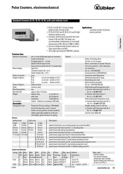
1076/2009• B 15..1 and B 16..1, 5 resp. 6-digit totaliser with manual reset• B 15..0, B 16..0 and B 18..0, 5, 6 and 8-digit totaliser without reset• Counters without front panel fit into front frames F1B and F2B. The latter canaccommodate combination of count with dimensions of 50 x 50 mm [1.969 x 1.969“]• Can be combined with preset counter of Type series BVa and HVa.• Very high operating life (200 Mio. pulses)Applications:counting number of pieces, events, periodsTechnical data:Electrical connection:pin ø 1.6 mm [0.063] with push on connector (count mechanism)for flying leads 0.5 ... 1.0 mm 2[322.58 x 645.16 square inch]flat pin 0.8x2.8 mm [0.315x0.11“] (socket box)Rated voltage:type 0/1/a:12/24/48/115/230 V DC ±10 % 24/48/115/230 V AC ± 10 %Colour of counter:grey Height of figures:B 15 2.4 x 4.5 mm [0.094 x 0.177“] B 16 2 x 4.5 mm [0.079 x 0.177“] B 18 2 x 4 mm [0.079 x 0.158“] Colour of figures:white on black Shaft:stainless steel Mounting position:anyOperating life:approx. 200 x 106pulses Weight:without reset 81 g [2.857 oz]with reset 83 g [2.928 oz]socket box 14 g [0.494 oz]Test voltage: 2 000 V ~ effective, according to VDE 0435Accessories:Transparent cover:Protection IP 55 according to DIN 400050 from front side when cover is closed.Gasket: oil and gasoline resistant synthetic rubber especially suitable for acids and electrolytes, good resistance to ageingOptions:– Colour of housing: black (For Art. no. ref. to type)– Electr. connection at counter: flat pins 0.8 x 2.8 mm [0.315 x 1.102“] with push on connectorsArt. no. 1.2X7.XXX.XXX–Screw terminal 1.2.XXX.XXX.023– Connection with flying leads – Extended temperature range – Key locking zero reset –Reset only from backside Art. no. 1.2XX.XXX.XXX.024– Knob locking with transparent cover a.) Counter with front bezel size No. 3Art. no. 1.2X0.7XX.XXXb.) Counter with front frame F 1Art. no. 1.2X1.7XX.XXX– Knob locking with transparent cover a.) Counter with front bezel size No. 3Art. no. 1.2X0.8XX.XXX.XXX – Flexible sealing cover K 1 (IP 54)a.) Counter with front bezel size No. 3Art. no. 1.2X0.6XX.XXX –Key for reset: G050 265Order code:– Article number– For special voltages,please give type, voltage,kind of voltage and series e.g. B 16.31, 4.5 V DC, 0.P u l s e C o u n t e r sType B 16.00B 16.0012 V24 V115 V230 V(6-digit)Art. no.Art. no.Art. no.Art. no.DC (10 Imp/s) 1.230.002.012 1.230.002.013DC (25 Imp/s) 1.230.002.032 1.230.002.033AC (18 Imp/s) 1.230.002.061 1.230.002.064 1.230.002.066Standard colour: beigeColour of housing black:Art. no. 1.230.001.XXXType B 18.00B 18.0012 V24 V115 V230 V(8-digit)Art. no.Art. no.Art. no.Art. no.DC (10 Imp/s) 1.260.002.012 1.260.002.013*DC (25 Imp/s) 1.260.002.032 1.260.002.033*AC (18 Imp/s) 1.260.002.061 1.260.002.064 1.260.002.066Standard colour: beigeColour of housing black:Art. no. 1.260.001.XXXFurther stock models: 1.260.001.013 Type B 16.10B 16.1012 V24 V115 V230 V(6-digit)Art. no.Art. no.Art. no.Art. no.DC (10 Imp/s) 1.230.100.012 1.230.100.013DC (25 Imp/s) 1.230.100.032 1.230.100.033AC (18 Imp/s) 1.230.100.061 1.230.100.064 1.230.100.066*standard stock modelStandard colour: grey6/2009Type B 18.10B 18.1012 V24 V115 V230 V(8-digit)Art. no.Art. no.Art. no.Art. no.DC (10 Imp/s) 1.260.100.012 1.260.100.013*DC (25 Imp/s) 1.260.100.032 1.260.100.033*AC (18 Imp/s) 1.260.100.061 1.260.100.064 1.260.100.066Standard colour: greyColour of housing black:Art. no. 1.260.101.XXXType B 16.20B 16.2012 V24 V115 V230 V(6-digit)Art. no.Art. no.Art. no.Art. no.DC (10 Imp/s) 1.230.200.012 1.230.200.013*DC (25 Imp/s) 1.230.200.032 1.230.200.033*AC (18 Imp/s) 1.230.200.061 1.230.200.064 1.230.200.066Standard colour: greyColour of housing black:Art. no. 1.230.201.XXXFurther stock models1.237.201.066230 V AC/a flat pinsType B 18.20B 18.2012 V24 V115 V230 V(8-digit)Art. no.Art. no.Art. no.Art. no.DC (10 Imp/s) 1.260.200.012 1.260.200.013*DC (25 Imp/s) 1.260.200.032 1.260.200.033*AC (18 Imp/s) 1.260.200.061 1.260.200.064 1.260.200.066*Standard colour: greyColour of housing black:Art. no. 1.260.201.XXXFurther stock models1.260.201.013, 1.260.201.066*standard stock modelPulseCounters1096/20091106/2009Type B 16.30B 16.3012 V 24 V 115 V 230 V (6-digit)Art. no.Art. no.Art. no.Art. no.DC (10 Imp/s) 1.230.300.012 1.230.300.013DC (25 Imp/s) 1.230.300.0321.230.300.033AC (18 Imp/s)1.230.300.0611.230.300.064 1.230.300.066Standard colour: grey Colour of housing black:Art. no. 1.230.301.XXXType B 18.30B 18.3012 V 24 V 115 V 230 V (8-digit)Art. no.Art. no.Art. no.Art. no.DC (10 Imp/s) 1.260.300.012 1.260.300.013DC (25 Imp/s) 1.260.300.0321.260.300.033AC (18 Imp/s)1.260.300.0611.260.300.064 1.260.300.066Standard colour: grey Colour of housing black:Art. no. 1.260.301.XXXType F1 B 16.00F1 B 16.0012 V 24 V 115 V 230 V (6-digit)Art. no.Art. no.Art. no.Art. no.DC (10 Imp/s) 1.231.502.012 1.231.502.013DC (25 Imp/s) 1.231.502.0321.231.502.033AC (18 Imp/s) 1.231.502.0611.231.502.064 1.231.502.066Standard colour: beige Colour of housing black:Art. no. 1.231.501.XXXType F1 B 18.00F1 B 18.0012 V24 V115 V230 V(8-digit)Art. no.Art. no.Art. no.Art. no.DC (10 Imp/s) 1.261.502.012 1.261.502.013DC (25 Imp/s) 1.261.502.032 1.261.502.033AC (18 Imp/s) 1.261.502.061 1.261.502.064 1.261.502.066Standard colour: beigeColour of housing black:Art. no. 1.261.501.XXXType B 16.01B 16.0112 V24 V115 V230 V(6-digit)Art. no.Art. no.Art. no.Art. no.DC (10 Imp/s) 1.230.012.012 1.230.012.013*DC (25 Imp/s) 1.230.012.032 1.230.012.033*AC (18 Imp/s) 1.230.012.061 1.230.012.064 1.230.012.066*Standard colour: beigeColour of housing black:Art. no. 1.230.011.XXX*standard stock modelAdditional stock models:1.230.011.01324 V DC/0 bw1.230.011.03324 V DC/1 bw1.230.011.066230 V AC/a bwPulseCounters1116/2009Type B 15.11B 15.1112 V24 V115 V230 V(5-digit)Art. no.Art. no.Art. no.Art. no.DC (10 Imp/s) 1.200.110.012 1.200.110.013DC (25 Imp/s) 1.200.110.032 1.200.110.033AC (18 Imp/s) 1.200.110.061 1.200.110.064 1.200.110.066Type B 16.11B 16.1112 V24 V115 V230 V(6-digit)Art. no.Art. no.Art. no.Art. no.DC (10 Imp/s) 1.230.110.012 1.230.110.013*DC (25 Imp/s) 1.230.110.032 1.230.110.033*AC (18 Imp/s) 1.230.110.061* 1.230.110.064* 1.230.110.066*Standard colour: greyColour of housing black:Art. no. 1.230.111.XXX*standard stock modelAdditional stock models:1.230.011.03324 V DC/1 swStandard colour: grey6/2009Type B 16.21B 16.2112 V24 V115 V230 V(6-digit)Art. no.Art. no.Art. no.Art. no.DC (10 Imp/s) 1.230.210.012* 1.230.210.013*DC (25 Imp/s) 1.230.210.032 1.230.210.033*AC (18 Imp/s) 1.230.210.061 1.230.210.064 1.230.210.066*Standard colour: greyColour of housing black:Art. no. 1.230.211.XXXFurther stock models:1.230.211.01324 V DC/0 sw1.230.211.03324 V DC/1 sw1.230.211.066230 V AC/a sw1.230.217.01324 V DC/0 sw vs1.237.211.066230 V AC/a sw1.237.201.066230 V AC/a sw flat pinType B 15.21B 15.2112 V24 V115 V230 V(5-digit)Art. no.Art. no.Art. no.Art. no.DC (10 Imp/s) 1.200.210.012 1.200.210.013*DC (25 Imp/s) 1.200.210.032 1.200.210.033AC (18 Imp/s) 1.200.210.061 1.200.210.064 1.200.210.066*standard stock modelStandard colour: grey*standard stock modelPulseCounters1136/2009Type F1 B 16.01F1 B 16.0112 V 24 V 115 V 230 V (6-digit)Art. no.Art. no.Art. no.Art. no.DC (10 Imp/s) 1.231.512.012 1.231.512.013DC (25 Imp/s) 1.231.512.0321.231.512.033AC (18 Imp/s)1.231.512.0611.231.512.064 1.231.512.066Standard colour: beige Colour of housing black:Art. no. 1.231.511.XXXType B 16.31B 16.3112 V 24 V 115 V 230 V (6-digit)Art. no.Art. no.Art. no.Art. no.DC (10 Imp/s) 1.230.310.012 1.230.310.013*DC (25 Imp/s) 1.230.310.0321.230.310.033AC (18 Imp/s)1.230.310.0611.230.310.064 1.230.310.066Standard colour: grey Colour of housing black:Art. no. 1.230.311.XXXFurther stock models:1.237.310.066 230 V AC/a flat pinB 15.21 vs Dvs B 16.31Dv B 16.31K1B 15.31945.2*standard stock model1141/2009。
德国KUBLER库伯勒绝对值编码器由机械位置确定编码,它无需记忆

德国KUBLER库伯勒绝对值编码器由机械位置确定编码,它无需记忆我公司是一家以经销销售欧美进口自动化产品的综合性贸易公司,主要负责欧美品牌的采购德国KUBLER库伯勒绝对值编码器由机械位置确定编码,它无需记忆绝对编码器光码盘上有许多道光通道刻线,每道刻线依次以2线、4线、8线、16线编排,这样,在编码器的每一个位置,通过读取每道刻线的通、暗,获得一组从2的零次方到2的n-1次方的的2进制编码(格雷码),这就称为n位绝对编码器。
这样的编码器是由光电码盘进行记忆的。
绝对编码器由机械位置确定编码,它无需记忆,无需找参考点,而且不用一直计数,什么时候需要知道位置,什么时候就去读取它的位置。
这样,编码器的抗干扰特性、数据的可靠性大大提高了。
从单圈KUBLER绝对值编码器到多圈KUBLER绝对值编码器,绝对值旋转单圈KUBLER绝对值编码器,以转动中测量光电码盘各道刻线,以获取的编码,当转动超过360度时,编码又回到原点,这样就不符合绝对编码的原则,这样的编码只能用于旋转范围360度以内的测量,称为单圈KUBLER绝对值编码器。
这是能将电动机一转内的角度数据输出到外部目标的检测器。
绝对编码器一般能够以 8 到 12位输出360 °增量编码器有一个缺点:即当发生电源故障时丢失轴位置。
然而,对于绝对编码器来说,即使发生电源故障也不丢失轴位置。
可以输出各种代码,诸如二进制代码和 BCD 代码。
绝对编码器比增量编码器更昂贵、更精确、更大。
参考“编码器”绝对编码器绝对编码器光码盘上有许多道光通道刻线,每道刻线依次以2线、4线、8线、16线编排,在编码器的每一个位置,通过读取每道刻线的通、暗,获得一组百从2的零次方到2的n-1次方的的2进制编码(格雷码)。
绝对编码器由机械位置确定编码,它无需记忆,无需找参考点,而且不用一直计数,什么时候需要知道位置,什么时候就去读取它的位置。
绝对型编码器有量程范围,适合用在一些特殊机床上。
更换Kubler编码器后要怎么调零呢?

更换Kubler编码器后要怎么调零呢?当我们在更换Kubler编码器后要怎么调零呢?答:我们在更换库伯勒编码器后,需要将机器重新调零以确保精准度。
调零过程可以分为几个步骤。
首先需要检查新编码器是否正确接线,确保信号可以正常传输。
接着可以通过手动操作机械臂或轴来确定当前位置,并记录下实际位置值。
然后将编码器的位置值与实际位置值进行比对,如果存在偏差,则需要进行调整。
在调整过程中,可以通过调整编码器零点或机器初始位置等方法来纠正误差,直到两个位置值相符为止。
完成调零后,还需要进行一些测试以确保机器的精度和稳定性。
如果测试结果正常,则可以开始正常的运行。
总的来说,调零过程需要耐心和细心,必须注意各个环节中的细节问题以确保调整效果。
同时,由于不同机器的结构和编码器的类型也有所不同,因此在实际操作中还需要参考相关设备的使用说明或者咨询专业调试人员以确保安全和顺利完成调整。
Kubler电机编码器调零的主要目的是建立一个参考点或零点,以确保准确的位置控制和追踪。
以下是一些调零电机编码器的原因:1.定位准确性:电机编码器提供了对电机位置的准确反馈。
调零编码器可以确保在电机启动或重新启动后,位置计数器的起始点是准确的。
这样可以避免累积误差,保证位置控制的准确性。
2.系统复位:在某些情况下,需要将电机系统重置到已知状态。
通过调零编码器,可以将位置计数器归零,使得当前位置成为系统的新起始点。
这在一些自动化应用中很常见,例如机器人操作或工业生产线的起始位置。
3.偏移修正:电机编码器可能存在一些零点偏移或安装误差。
调零编码器可以通过将当前位置设置为零点来纠正这些偏移,以便准确追踪电机位置。
4.故障恢复:在电机系统故障后,重新校准编码器是恢复正常操作的重要步骤。
通过调零编码器,可以确保在故障恢复后,电机的位置计数器重新同步,并准确追踪位置。
总而言之,电机编码器调零是为了确保准确的位置控制和追踪,纠正偏移误差,并使系统能够在已知状态下操作。
kubler库伯勒编码器

8.3651.2332.4321,8.3651.2332.4411,8.3651.2332.4421,
8.3651.2334.1311, 8.3651.2334.1321, 8.3651.2334.1411, 8.3651.2334.1421, 8.3651.2334.2311, 8.3651.2334.2321, 8.3651.2334.2411, 8.3651.2334.2421, 8.3651.2334.3311, 8.3651.2334.3321, 8.3651.2334.3411, 8.3651.2334.3421, 8.3651.2334.4311, 8.3651.2334.4321, 8.3651.2334.4411, 8.3651.2334.4421,8.3651.2342.1311, 8.3651.2342.1321, 8.3651.2342.1411, 8.3651.2342.1421, 8.3651.2342.2311, 8.3651.2342.2321, 8.3651.2342.2411, 8.3651.2342.2421, 8.3651.2342.3311, 8.3651.2342.3321, 8.3651.2342.3411, 8.3651.2342.3421,8.3651.2342.4311,8.3651.2342.4321,
8.3651.2342.4411,8.3651.2342.4421,8.3651.2344.1311, 8.3651.2344.1321, 8.3651.2344.1411, 8.3651.2344.1421, 8.3651.2344.2311, 8.3651.2344.2321, 8.3651.2344.2411, 8.3651.2344.2421, 8.3651.2344.3311, 8.3651.2344.3321, 8.3651.2344.3411, 8.3651.2344.3421, 8.3651.2344.4311, 8.3651.2344.4321, 8.3651.2344.4411, 8.3651.2344.4421,
库伯勒编码器技术手册

库伯勒编码器技术手册库伯勒编码器是数字电子设备中常用的一种传感器,用于将旋转或线性运动转换为数字信号。
本手册旨在介绍库伯勒编码器的原理、种类、应用以及安装和调试方法。
I. 原理及分类库伯勒编码器基于光电、电磁或霍尔效应等原理工作。
其中最常见的类型为光电编码器和磁性编码器。
1. 光电编码器光电编码器通过光电传感器和光栅来测量运动。
光栅通常由透明和不透明的标记组成,光电传感器则可以检测到光栅上光线的变化,进而转换为电信号。
光电编码器具有高分辨率、精确度高等优点。
2. 磁性编码器磁性编码器利用磁性材料和传感器来测量运动。
通常由精密的磁性标记和霍尔传感器组成。
磁性编码器具有较高的稳定性和耐用性,适用于恶劣环境条件下的应用。
II. 应用领域库伯勒编码器广泛应用于各个领域,例如:1. 机械加工库伯勒编码器用于CNC机床、车床和磨床等机械加工设备中,用于控制运动的精度和速度。
通过与数控系统的配合,可以实现高精度加工。
2. 机器人技术库伯勒编码器在机器人技术中发挥着重要作用。
它可以精确检测机器人的关节角度和位置,从而实现精确的运动和控制。
3. 自动化系统在自动化系统中,库伯勒编码器用于测量和控制各种设备的位置、速度和加速度。
例如,常用于电梯、输送带、自动门等系统中,确保安全和效率。
4. 医疗设备库伯勒编码器应用于医疗设备中,例如手术机器人、医学成像设备等。
它可以提供精确的位置和运动信息,帮助医生进行精细操作或诊断。
III. 安装与调试正确的安装和调试对于库伯勒编码器的正常运行至关重要。
以下是一些建议和步骤:1. 安装确保库伯勒编码器与被测量的运动装置正确连接,避免摩擦和松动。
根据具体类型选择合适的安装方式,例如夹紧安装、板式安装等。
2. 供电与信号连接库伯勒编码器通常需要外部供电,并通过信号线与控制系统连接。
确保供电电压和信号电平的匹配,并正确连接接线端子。
3. 调试在启动之前进行调试是必要的。
使用示波器或编码器测试设备,检查输出信号的稳定性和准确性。
广联分享德国kubler编码器的基本原理

广联分享德国kubler编码器的基本原理kubler编码器是通过把机械角度物理量的变化转变成电信号的一种装置:在传感器的分类中,他归属于角位移传感器。
根据编码器的这一-特性,编码器主要用于测量转动物体的角位移量,角速度,角加速度,通过编码器把这些物理量转变成电信号输出给控制系统或仪表,控制系统或仪表根据这些量来控制驱动装置。
kubler编码器基本原理构造编码器主要是由码盘(圆光栅、指示光栅)、机体、发光器件、感光器件等部件组成。
(1)圆光栅是由涂膜在透明材料或刻画在金属材料上的成放射状的明暗相间的条纹组成的。
一个相邻条纹间距称为-一个栅节,光栅整周栅节数就是编码器的脉冲数(分辨率)。
(2)指示光栅是一片固定不动的,但窗口条纹刻线同圆光栅条纹刻线相同的光栅片。
(3)机体是装配圆光栅,指示光栅等部件的载体。
(4)发光器件一般是红外发光管。
(5)感光器件是高频光敏元件:一般有硅光电池和光敏三极管。
库伯勒编码器的工作原理由圆光栅和指示光栅组成--对扫描系统,在扫描系统的一侧投射--束红外光,在扫描系统的另一侧的感光器件就可以收到扫描光信号:当圆光栅转动时,感光器件接收到的扫描光信号会发生变化,感光器件可以把光信号转变成电信号并输出给控制系统或仪表。
一般编码器的输出信号为两列成90度相位差的Sin信号和Cos信号(这是由指示光栅的窗口条纹刻线保证的) ;这些信号的周期等于圆光栅转过一个栅节(P)的移动时间,对Sin 信号和Cos信号进行放大及整形就可输出方波脉冲信号。
kubler编码器的应用场合十分的广泛,在此列举几个简单事例:(1)数控机床对加工工件自动检测就是通过编码器来进行检测的:数控机床刀架的对零校准也是通过编码器来实施的。
(2)编码器在PLC.上的应用:一般PLC.上都有高速信号输入口,编码器可以作为高速信号输入元件,使PLC更加迅速和精准地实施闭环控制。
而在变频器上其一般接变频器的 PG卡上。
- 1、下载文档前请自行甄别文档内容的完整性,平台不提供额外的编辑、内容补充、找答案等附加服务。
- 2、"仅部分预览"的文档,不可在线预览部分如存在完整性等问题,可反馈申请退款(可完整预览的文档不适用该条件!)。
- 3、如文档侵犯您的权益,请联系客服反馈,我们会尽快为您处理(人工客服工作时间:9:00-18:30)。
库伯勒编码器技术手册
一、编码器概述
编码器是一种测量旋转或线性运动位置和速度的装置,通常由一个可转动的转子和一个固定的定子组成。
转子上通常有扇区或槽,当转子转动时,这些扇区或槽通过定子,并被定子内的传感器检测到,从而转化为电信号的变化。
通过对这些电信号的处理,可以获得旋转或线性运动的位置、速度和方向等信息。
二、编码器工作原理
编码器的工作原理主要基于电磁感应原理。
当编码器的转子上的扇区或槽通过定子时,会改变定子内的磁场分布,从而产生感应电动势。
感应电动势的大小和方向与通过的扇区或槽的位置和速度有关,通过测量感应电动势,就可以得到旋转或线性运动的位置和速度信息。
三、编码器类型和规格
编码器有多种类型,如增量式编码器、绝对式编码器、旋转变压器等。
规格方面,编码器的规格主要取决于其测量范围、精度、工作电压、输出信号等参数。
选择合适的编码器类型和规格需要根据实际应用需求进行选择。
四、编码器安装与操作
安装编码器时,需要保证其测量轴与被测轴的对准,以减小测量误差。
操作编码器时,需要按照规定的电源电压和工作频率进行供电和信号处理,以保证其正常工作。
同时,还需要定期对编码器进行检查和维护,以保证其长期稳定工作。
五、编码器应用领域
编码器在工业自动化领域得到了广泛的应用,如电机控制系统、机器人、数控机床等。
此外,在航空、能源、交通等领域也有一定的应用。
六、编码器性能指标
编码器的性能指标主要包括测量精度、分辨率、工作电压、输出信号等。
其中,测量精度是指编码器实际输出值与理论输出值之间的误差;分辨率是指编码器输出信号的位数;工作电压是指编码器正常工作的电压范围;输出信号是指编码器的输出类型(如模拟信号或数字信号)。
七、编码器常见故障与排除
编码器的常见故障包括测量误差大、工作不稳定等。
可能的原因有:安装不良、连接线路有问题、工作环境恶劣等。
对于这些故障,可以采取相应的措施进行排除,如重新安装编码器、检查连接线路、改善工作环境等。
八、编码器维护与保养
为了保持编码器的性能和延长其使用寿命,需要定期对其进行维护和保养。
例如,定期检查其外观和螺丝等是否松动;保持清洁,避免尘埃和杂质的进入;在长期不使用的情况下,应存放在干燥的地方并定期通电热化等。
九、编码器发展趋势与未来展望
随着科技的不断进步和应用需求的不断提高,编码器也在不断发展和改进。
未来,编码器将更加智能化、高精度化、小型化和集成化。
同时,随着物联网和
云计算技术的发展,编码器的远程监控和维护也将成为可能,这为提高设备运行效率和降低维护成本提供了更好的解决方案。
十、案例分析
为了帮助读者更好地理解和应用编码器,本章节将提供一些编码器的应用案例。
这些案例将涵盖不同的应用场景和行业,帮助读者了解编码器在不同领域中的应用和解决方案。
案例一:机器人关节位置控制
在一个工业机器人系统中,编码器被用于测量和控制系统中的每个关节的旋转角度。
通过将编码器的输出信号连接到控制系统的微处理器中,机器人能够实时获取每个关节的位置信息,并据此调整其运动轨迹,实现精确的位置控制。
案例二:电梯门开关控制
在一个电梯系统中,编码器被用于检测电梯门的开关状态。
当电梯门关闭时,编码器将检测到门的位置,并将信号发送给控制系统。
如果检测到门未完全关闭,控制系统将发出警报并停止电梯的运行,以保障乘客的安全。
十一、总结
本手册对编码器的基本概念、工作原理、类型和规格、安装与操作、应用领域、性能指标、常见故障与排除、维护与保养、发展趋势与未来展望等方面进行了详细的介绍。
通过阅读本手册,读者可以全面了解编码器的相关知识,为其在实际应用中提供指导和帮助。
同时,本手册还通过案例分析,向读者展示了编码
器在不同领域中的应用和解决方案。
希望本手册能够帮助读者更好地应用和维护编码器,提高设备运行效率和降低维护成本。