
富士通fi-6225LA安装说明
Fi-6225LA扫描仪安装说明
1硬件部分安装图例如下,更详细内容请参考设备内附说明书1.1 解除运输锁
1.2 安装自动进纸器
1.3安装电源线1.4 安装usb线
2软件部分如下:
1.使用管理员账户进入系统,下载Ftp://fhyh:***********.1.7/文件到D:\重要备份\驱动程序\目录下,成功安装后再连接扫描仪。
2.扫描仪可连接在主机任意一个USB接口。
扫描仪设置完成后,尽量使用一个USB接口,如需连接其他USB接口,需要重新设置扫描仪参数。
扫描仪设置方法如下:
a)使用厂家自带扫描软件(ScandAll 21)扫描一次。
b)在ScandAll 21中设置如下扫描仪参数(定制驱动中已设置,以下为检
查项),如下图所示:。
Fujitsu MHZ2-CJ Series FDE HDD安装与设置指南说明书
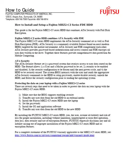
How to GuideFUJITSU COMPUTER PRODUCTS OF AMERICA, INC.1255 E. Arques Ave., Sunnyvale, CA, 94085Telephone: 408-746-7000 Facsimile: 408-746-6914How to Install and Setup a Fujitsu MHZ2-CJ Series FDE HDDThis guide is for the Fujitsu MHZ2-CJ series HDD that combines ATA Security with Full DiskEncryption.Fujitsu MHZ2-CJ series HDD combines ATA Security with FDEThe Fujitsu MHZ2-CJ series HDD implements the ATA-Security command set as well as FullDisk Encryption (FDE). ATA Security is a commonly available feature found on most modernHDDs targeted for the mobile environment. ATA Security and FDE complement each other.ATA Security provides password-based authentication and access control and FDE encrypts alluser data written to the drive. Together these features provide comprehensive data protection forMobile Computing.ATA SecurityThe ATA-Security feature set is a password system that restricts access to user data stored on theHDD. The feature allows 1) a User and a Master password to be set, 2) security to be enabledand disabled, 3) the security configuration to be frozen until the next power cycle, and 4) theHDD to be securely erased. The system BIOS interacts with the user and sends the appropriateATA-Security commands to the HDD to setup passwords, enable/disable security, unlock theHDD, and freeze the security configuration prior to loading the operating system.Protecting the data on your laptop with a Fujitsu MHZ2-CJ seriesThere are several steps that need to be taken in order to protect the data on your laptop with theFujitsu MHZ2-CJ series HDD.1)Make sure that the BIOS supports enabling security2)Transfer any user data from the old HDD to an external media3)Install the Fujitsu MHZ2-CJ series HDD into the laptop4)Set the passwords5)Install the OS and application software6)Transfer any user data from the old HDD to the new HDDBy installing the FUJITSU MHZ2-CJ series HDD, you, the user, assume all liability and risk ofloss for proper installation, including without limitation, uninterrupted or error-free operation,data loss, data security and use of encryption features. FUJITSU expressly disclaims any and allliability arising out of improper installation of the Fujitsu MHZ2-CJ series HDD and itsencryption features.For a complete statement of the FUJITSU warranty applicable to the MHZ2-CJ series HDD, see: /us/services/computing/storage/hdd/warranty/guide.html1. Make sure that the BIOS supports enabling securityIn the BIOS Setup Program, verify that the BIOS supports a “Hard Disk” password. It could also be called a “Hard Drive” password or a “Disk Drive” password or something similar. It is not the “BIOS” password or the “System” password.If the BIOS does not support a Hard Disk password, then a User password cannot be set and security cannot be enabled and the full benefit of FDE cannot be realized.If the BIOS supports a Hard Disk password, then a User password can be set, security can be enabled, and the full benefit of FDE can be realized.For example, the following screen shot indicates that the BIOS supports enabling security. There is a selection on the “Security” screen for “Hard Disk Security.” Other BIOSs may look different from this example.2) Transfer any user data from the old HDD to an external mediaAny user data that needs to be retained can be copied to an external media before the old HDD is removed. After the new HDD is installed and the operating system is installed, the data can be copied from the external media to the new HDD.3) Install the Fujitsu MHZ2-CJ series HDD into the laptopWhen replacing the laptop’s current HDD with a Fujitsu MHZ2-CJ series HDD, all the same installation steps need to be taken as with any other HDD, with the possible addition of the step to enable security.The Fujitsu MHZ2-CJ series HDD is physically installed into the laptop in the same manner that any other HDD would be installed. FDE poses nothing special for the physical installation.4) Set User PasswordAfter installing the new HDD, the next step is to enable security.The following screen shot shows that the BIOS supports both a User Password and a Master Password.The following screen shot shows the interaction to set the User Password.The following screen shot shows the interaction to set the Master Password.Refer to the help section of your system’s BIOS menus for information on setting the Hard Disk Passwords.Normal operation with security enabledWhen security is enabled, whenever the system is powered on the HDD will be locked and the BIOS will ask for a password. The User password can be used to unlock the HDD. The HDD will remain unlocked until the system is powered off.The following screen shot shows the interaction to unlock the HDD when the laptop is powered on.Do not forget your password!If you forget your password, then your data is unrecoverable.5) Install The OS and application softwareThe new Fujitsu MHZ2-CJ series HDD needs to have the operating system and other software installed. The operating system and other software can be installed by running the normal software installers or by transferring a preconfigured image to the new HDD.6) Transfer any user data from external media to the new HDDAfter the operating system and other software have been installed any user data can be copied to the new HDD.If the user data has already been copied to an external media, now is the time to copy it from the external media to the new HDD.Advanced Secure EraseNot all BIOSs directly support the Advanced Secure Erase function. If your BIOS does support this function, then refer to the help section of your system’s BIOS menus for information on performing this function.If your BIOS does not support the Advanced Secure Erase function, then you need to use an alternative approach.A freeware utility called HDDErase is available from the Center for Magnetic Recording Research at the University of California, San Diego./people/Hughes/SecureErase.shtmlThis utility is able to initiate an Advanced Secure Erase of the HDD. The utility comes with a text file called HDDEraseReadMe.txt that describes what needs to be done in order to erase the HDD.FUJITSU EXPRESSLY DISCLAIMS ANY AND ALL WARRANTIES WITH RESPECT TO THE UTILITY HDDERASE, EXPRESS OR IMPLIED, INCLUDING WITHOUT LIMITATION IMPLIED WARRANTIES OF MERCHANTABILITY AND FITNESS FOR A PARTICULAR PURPOSE, WARRANTIES OF NON-INFRINGEMENT, AND ANY WARRANTY, EXPRESS OR IMPLIED, THAT THE UTILITY OR ITS OPERATION WILL BE UNINTERRUPTED, ERROR-FREE OR VIRUS FREE. FUJITSU EXPRESSLY DISCLAIMS ANY AND ALL LIABILITY ARISING OUT OF USE OF THE UTILITY HDDERASE. YOU, THE USER, ASSUME ALL RISKS WHEN DOWNLOADING OR USING THE UTILITY.。
富士通打印机安装图解
富士通打印机安装图解富士通打印机安装图解说起打印机,大家都不会陌生,因为,我们生活中有很多时候都会用到打印机。
比如,打印一些重要的资料,文件等。
那么,大家有没有听说过针式打印机呢?针式打印机与一般的打印机有所不同,是从一般打印机上进化而来的。
大家也许不知道针式打印机怎么使用,下面我们就以富士通针式打印机为例,详细介绍一下富士通针式打印机的使用说明书。
富士通针式打印机,绝大部分都是地推式打印,就是你把打印纸放在感应外口,会自动吸取纸张,然后卷进去。
在安装打印驱动之后,一定要设置好打印机相关功能才能进行打印。
首先要进行局域网打印共享设置。
第一步是安装打印机及其驱动程序,并将打印机设置为局域网共享。
第二步是自定义打印纸张规格。
第三步是电脑连接打印机并设置为默认打印机。
其次,就要对IE页面进行设置,打开IE浏览器,依次点击“文件-页面设置”,将纸张大小改为“120”,清空页眉和页脚,方向选为纵向,将页边距的`“左”、“右”均设置为7,“上”、“下”清空,然后点“确定”就可以了。
接着就是对软件参数进行设置,依次点击“系统管理-参数设置-系统参数”,选择“连续走纸”、“120”、“1联”即可。
然后,就可以对富士通针式打印机进行操作了,先打开控制面板-打印机和传真,再对你的打印机点右键-属性,在常规里面点击相对应的机图标,选择打印首选项,切换到纸张/质量>>点高级>>查看纸张规格中所用的是那种纸张并记下名称,最后就可以打印了。
需要注意的是:富士通针式打印机控制面板-打印机和传真要对着空白的地方点右键;点开“有一个服务器”属性在格式里面找到要打印那种纸的名称查看下面格式描述中对于该纸张的尺寸设定,如果可以修改的话,慢慢修改到合适值;如果不能改动的话构选创建新格式,填入一个表格名,再填入要的尺寸,保存后再次来到刚才查看打印机所用纸张的地方,把纸张换为刚刚建立的纸张即可。
以上便是对富士通针式打印机使用的相关介绍和需要注意的事项。
富士通产品温敏打印机FTP-62HMCL系列说明书
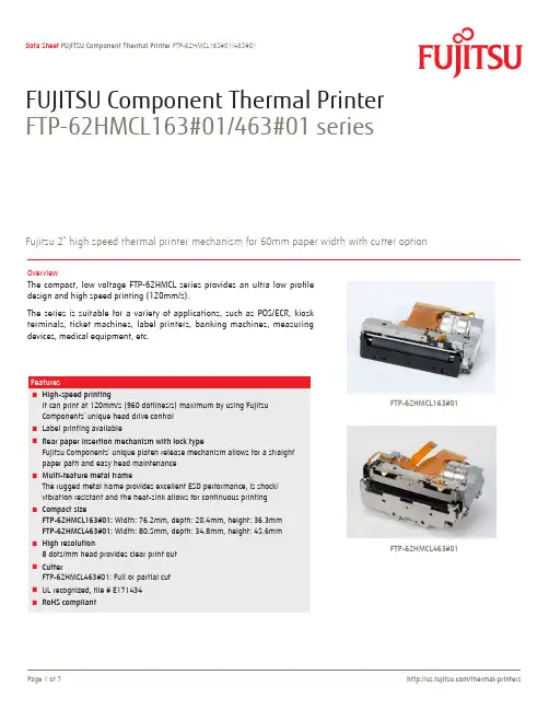
FUJITSU Component Thermal Printer FTP-62HMCL163#01/463#01 seriesFujitsu 2” high speed thermal printer mechanism for 60mm paper width with cutter optionOverviewThe compact, low voltage FTP-62HMCL series provides an ultra low profiledesign and high speed printing (120mm/s).The series is suitable for a variety of applications, such as POS/ECR, kioskterminals, ticket machines, label printers, banking machines, measuringdevices, medical equipment, etc.■High-speed printingIt can print at 120mm/s (960 dotlines/s) maximum by using FujitsuComponents’ unique head drive control■Label printing available■Rear paper insertion mechanism with lock typeFujitsu Components’ unique platen release mechanism allows for a straight paper path and easy head maintenance■Multi-feature metal frameThe rugged metal frame provides excellent ESD performance, is shock/vibration resistant and the heat-sink allows for continuous printing■Compact sizeFTP-62HMCL163#01: Width: 76.2mm, depth: 20.4mm, height: 36.3mm FTP-62HMCL463#01: Width: 80.5mm, depth: 34.8mm, height: 45.6mm■High resolution8 dots/mm head provides clear print out■CutterFTP-62HMCL463#01: Full or partial cut■UL recognized, file # E171434■RoHS compliant FTP-62HMCL163#01FTP-62HMCL463#01Item Part NumberPrinter mechanism Back insertion FTP-62HMCL163#01 (60mm paper width, without cutter)FTP-62HMCL463#01 (60mm paper width, with cutter) Interface board FTP-62HDSL101#01 (ANK, Thai, JIS Kanji) *1FTP-62HDSL101#02 (ANK, Thai, Traditional Chinese) *1 LSI for driving FTP-62HCU101-RInterface cable USB FTP-629Y301#01 *2 RS-232C FTP-629Y302Power supply cable FTP-629Y601■Part numbers*1: Please see page 3 for basic interface board information. More detailed information can be obtained from your local Fujitsu sales representative. *2: USB mini-B type cable can be used.Item SpecificationsPart number FTP-62HMCL163#01FTP-62HMCL463#01Printing method Thermal sensitive line dot methodDot structure384 dots/linesDot pitch (horizontal)0.125mm (8 dots/mm) - Dot densityDot pitch (vertical)0.125mm (8 dots/mm) - Line feed pitchEffective printing area48mmNumber of columns ANK 36 columns/linePaper width60mm +0/-1Paper thickness60-150µm*160-80µm*1Cutting type---Full or partialPrinting speed120mm/s (960 dot lines/s)*2Power Head 4.2 to 9.5VDC 2.4A (Head voltage 7.2VDC, 176Ω, +25°C, concurrent applied dot number: 64 dots) Printer motor 4.2 to 9.5VDC 1.5A (using Fujitsu Components’ standard constant current circuit drive)Cutter motor 4.75 to 9.5VDC 1.5A max.Logic 3.3VDC±10% or 5VDC ±10% 0.1A maximumDimensions (WxDxH)Printer mechanism76.2 x 20.4 x 36.3mm80.5 x 34.8 x 45.6mmWeight Printer mechanism70g135gExpected life Head Pulse durability: 100 million pulse/dot (using Fujitsu Components’ standard driving method)Wear resistance: 100km (at 12.5% print ratio)Cutter--- 1 million cutsEnvironmental conditions Operating temperature-10°C to +50°C (no condensation), +5°C to +40°C print density guarantee Operating humidity20 to 85% RH (no condensation)Storage temperature-20°C to +60°C (excluding paper)Storage humidity 5 to 95% RH (no condensation)Detection functions Head temperature By thermistorPaper out/Mark detect By photointerrupterPlaten open By slide switchRecommended thermal sensitive paper High sensitive paper TF50KS-E45 (Nippon paper)Standard paper PD150R (Oji paper)Long term paper PD160R (Oji paper), TF50KJ-R (Nippon paper), HA220AA (Mitsubishi paper) *3*1: there may be exceptions.*2: Head voltage 7.6V, ambient temperature 25°C, concurrent applied dots 128 dots maximum, high speed mode, motor drive current 600mA/phase, use standard paper. *3: Maximum printing speed is 50mm/s when using HA220AA.■Specifications■Interface boardsItem SpecificationsPart number FTP-62HDSL101#01FTP-62HDSL101#02Power 6.0 to 9.5VCharacter type Alphanumeric, Kana, International & special OCR, enlarged characters, downloaded characters, externalcharactersExtended Kaji (#01)Traditional Chinese(#02)Characteristic dimensions (W x H)8 x 16 dots, 12 x 24 dots, 16 x 16 dots, 24 x 24 dots, 24 x 40 dots, 24 x 48 dots, 36 x 60 dotsInterface USB, RS232CDimensions (W x D)75 x 70 mm■ Dimensions• Printer mechanism: 2-inch Note: 1. Dimensions are nominal value) tolerance ±0.5mm unless otherwise specified. 2. Dimensions in ( ) is reference value.FTP-62HMCL163#01(Paper width)36.376.258mm 20.4Paper centerFeed motorPlaten release lever(At platen release)(Platen unit)■ Dimensions• Printer mechanism: 2-inch■Connector pin assignments of printer mechanism (FPC)No Signal Content I/O 1VSEN Paper sensor power IN 2PHK Cathode for photo interrupter OUT 3PHE Emitter for photo interrupter OUT 4N.C.Not connected-5N.C.Not connected-6VH Head drive power IN 7VH Head drive power IN 8VH Head drive power IN 9VH Head drive power IN 10DI Data in IN 11CLK Clock IN 12GND Head ground-13GND Head ground-14GND Head ground-15GND Head ground-16STB6Strobe6IN 17STB5Strobe5IN 18STB4Strobe4IN 19VDD Logic power IN 20TM Thermistor OUT 21TM Thermistor OUT 22STB3Strobe3IN 23STB2Strobe2IN 24STB1Strobe1IN 25GND Head ground-26GND Head ground-27GND Head ground-28GND Head ground-29/LAT/Data latch IN 30DO Data out OUT 31VH Head drive power IN 32VH Head drive power IN 33VH Head drive power IN 34VH Head drive power IN 35N.C.Not connected-36N.C.Not connected-37SW Platen release switch OUT 38SW Platen release switch OUT 39FG Flame ground-40MTM Motor thermistor OUTNo Signal ContentI/O1MT_B Excitation signal B SINK/SOURCE 2MT_B Excitation signal B SINK/SOURCE 3MT_/B Excitation signal /B SINK/SOURCE 4MT_/B Excitation signal /B SINK/SOURCE 5MT_A Excitation signal A SINK/SOURCE 6MT_A Excitation signal A SINK/SOURCE 7MT_/A Excitation signal /A SINK/SOURCE 8MT_/A Excitation signal /A SINK/SOURCE 9N.C.Not connected -10VSEN Paper sensor power IN 11PHE Emitter for photo interrupter OUT 12PHKCathode for photo interrupterOUT■ Connector pin assignments of cutter (FPC)No Signal Content I/O 41MTM Motor thermistor OUT 42N.C.Not connected -43MT_/A Excitation signal /A SINK/SOURCE 44MT_/A Excitation signal /A SINK/SOURCE 45MT_A Excitation signal A SINK/SOURCE 46MT_A Excitation signal A SINK/SOURCE 47MT_/B Excitation signal /B SINK/SOURCE 48MT_/B Excitation signal /B SINK/SOURCE 49MT_B Excitation signal B SINK/SOURCE 50MT_BExcitation signal BSINK/SOURCEContactCopyrightAll trademarks or registered trademarks are the property of their respective owners. Fujitsu Components America or its affiliates do not warrant that the content of datasheet is error free. In a continuing effort to improve our products Fujitsu Components America, Inc. or its affiliates reserve the right to change specifications/datasheets without prior notice. Copyright ©2020 Fujitsu Components America, Inc. All rights reserved. Revised February 14, 2020.JapanFUJITSU COMPONENT LIMITED Shinagawa Seaside Park Tower 12-4, Higashi-shinagawa 4-chome,Tokyo 140 0002, JapanTel: (81-3) 3450-1682Fax: (81-3) 3474-2385Email:***************** Web: /jp/group/fcl/en/North and South AmericaFUJITSU COMPONENTS AMERICA, INC.1230 E. Arques Ave., M\S 160 Sunnyvale, CA 94085 U.S.A.Tel: (1-408) 745-4900Fax: (1-408) 745-4970Email:*********************.com Web: /components/EuropeFUJITSU COMPONENTS EUROPE B.V.Diamantlaan 252132 WV Hoofddorp NetherlandsTel: (31-23) 5560910Fax: (31-23) 5560950Email:*****************.comWeb: /components/Asia PacificFUJITSU COMPONENTS ASIA, Ltd.102E Pasir Panjang Road#01-01 Citilink Warehouse Complex, Singapore 118529Tel: (65) 6375-8560 / Fax: (65) 6273-3021Email:***************.com/sg/products/devices/components/ChinaFUJITSU ELECTRONIC COMPONENTS (SHANGHAI) CO., LTD.Unit 4306, InterContinental Center100 Yu Tong Road, Shanghai 200070, China Tel: (86 21) 3253 0998 /Fax: (86 21) 3253 0997Email:***************.com/cn/products/devices/ components/Hong KongFUJITSU COMPONENTS HONG KONG Co., Ltd.Room 06, 28/F, Greenfield Tower, Concordia Plaza, No.1 Science Museum Road, Tsim Sha Tsui East, Kowloon, Hong Kong Tel: (852) 2881 8495 Fax: (852) 2894 9512Email:***************.com/sg/products/devices/components/KoreaFUJITSU COMPONENTS KOREA, LTD.Alpha Tower #403, 645 Sampyeong-dong, Bundang-gu, Seongnam-si, Gyeonggi-do, 13524 Korea Tel: (82 31) 708-7108Fax: (82 31) 709-7108Email:***************.com /sg/products/devices/components/。
Fujitsu磁盘驱动器安装指南与使用建议说明书

MAW3300NC/NP, MAW3147NC/NP, MAW3073NC/NPDISK DRIVES INST ALLATION GUIDECARE OF YOUR FUJITSU DRIVECareful handling and installation of your disk drive is paramount to the longevity of the unit. Serious damage can occur to the internal mechanisms if forces outside the environmental specifications are exerted to the casing. In transportation, always use the original packing in which the drive was supplied and avoid sharp changes in temperature to minimise the risk of condensation.Handling1. Never drop. Handle with care.2. Never move the disk drive while the disks are spinning. This is when the drive is powered on and also immediately after power off. Refer to the Start/Stop specification for your drive.3. Always turn off the power before connecting or disconnecting the interface cable. The same applies to changing any of the switches or terminal settings except Write protect switch on NP model drives.4. Never place the drive in the vicinity of strong magnetic fields such as monitors, televisions, or loudspeakers.5. Never use any cleaning agents or liquids on the drive.6. Always use an antistatic mat and wrist strap when handling the drive. Hold the drive by the Base casting and never touch the components on printed circuit board.7. Never remove any labels from the drive and do not deface them in any way; these labels are part of the disk drive design.8. Never open the disk enclosure for any reason. Doing so voids any warranty.9. Always pay close attention to the mounting specifications such as sway space and cooling. If the temperature difference between storage location and installation locations is more than 10°C, leave the drive in the new location for at least two hours for Temperature acclimation. This minimises any risk of condensation forming on the drive.The Drive needs NO preventative or periodic maintenance during its life time if properly used in the correct environment.INSTALLATION1. ORIENTATION–The drive can be installed in each six surface down orientations. Inclination from vertical or horizontal should not exceed 5°.2. MOUNTING SCREW INSTALLATION–When the mounting screw holes on the side of the drive are used, be sure to use the two pairs of outer holes. Do not use the center hole in conjunction with only one of the outer holes. The screws must not penetrate the drive by more than 5.0 millimeters. Impact caused by the electric driver must be within the device specifications.3. COOLING–Allow space above and below the drive to provide an adequate air flow. Fan cooling is recommended. The disk enclosure temperature measured at center of base cover (label side) should never exceed 60°C. See Table 1.Table 1. Reference value of airflowEnvironmental temperature Required velocity of airflow35°C >0.2m/s40°C> 0.5 m/s45°C> 0.9 m/s50°C> 1.5 m/s4. TERMINATION–A terminator should be installed externally at both ends of the SCSI bus.5. TERMINATOR POWER–Terminator power must be supplied to terminator for correct operation. This can be supplied from either the drive, except for NC model or the SCSI bus. If only NC model drives are connected to the SCCI bus, terminator power should be supplied externally.6. ATTACHING THE CABLES–To avoid possible damage to the drive, make sure the direction of the connector matches.CAUTION:Warranty may be avoided if damage to the connector is caused by wrong insertion.FUJITSU LIMITEDStorage Products Group4-1-1 Kamikodanaka, Nakahara-ku, Kawasaki 211-8588, Kanagawa-ken, JapanCopyright © 2005 FUJITSU LIMITED Corpora te /USA http://www.fcp/EUROPE /C141-E227-01ENDiagram and user-selectable options (on NP models only)Below is a diagram of the main board of SCSI disk drives and also a summary of the user-selectable options including guidelines for installation of the drives.This setting applies only for NP model drives.Pin 23Table 2. CN2 Terminal Setting (on NP models only)Pin #Setting Item Function1-2 SCSI ID 0 See Table 3.3-4 SCSI ID 15-6 SCSI ID 27-8 SCSI ID 39-10 Writeprotect Open……Write operation is enabled. (default)Short ……Write operation is disabled.11-12 Motor start mode Open ……Starting of motor is controlled with START/STOPUNIT command.(default)Short ……Motor is started immediately after power supply isturned on or microcode is downloaded.Narrow Open13-14 Force……16-bit bus mode(default)Short ……Pull upper 8bits and parity internally when drive isconnected to Narrow SCSI bus.15-16 Force Single Ended Open ……Follows DIFFSNS signal level on SCSI bus.(default)Short ……Single-Ended mode17 GND18, 19 N.C20 IDD Reset Input signal21-22 Remote LED Output signal23-24 Terminal power supply Open ……Drive does not supply terminator power to SCSI bus.Short ……Drive supplies terminator power to SCSI bus. (default)Table 3. SCSI ID Setting on CN2 (on NP models only)Pin 1-2 Pin 3-4 Pin 5-6 Pin 7-8 ID Pin 1-2 Pin 3-4 Pin 5-6 Pin 7-8 IDOpen Open Open Open 0 Open Open OpenS hort 8S hort 9S hort Open Open Open 1S hort Open OpenS hort 10S hort OpenOpenS hort Open Open 2 OpenS hort 11S hort OpenS hort Open Open 3S hortS hortS hortS hort 12S hort Open 4 Open OpenOpen OpenS hort 13S hortS hort OpenS hort OpenS hort Open 5S hortS hort 14S hortS hort Open 6 OpenS hortOpenS hortS hort 15(default)S hortS hort Open 7S hortS hortS hort。
富士通fi-800R 操作指南说明书

P3PC-6672-02ZTZ2FUJITSU 影像掃描器fi-800R操作指南目錄引言7使用手冊 (7)商標 (8)製造商 (8)安全資訊 (8)本手冊使用的標誌 (9)本手冊使用的縮寫名稱 (10)本手冊中的箭頭符號 (11)本手冊中的畫面圖例 (11)注意事項 (11)掃描器概要12主要功能 (12)部件和功能 (17)關於 LED 指示燈 (23)安裝軟體 (24)隨附軟體概要說明 (24)系統需求 (26)標準安裝 (建議選項) (27)自訂安裝 (28)基本操作29開啟/關閉電源 (29)如何開啟電源 (29)如何關閉電源 (29)進入省電模式和離開省電模式繼續使用 (30)設置 ADF 進紙槽 (送紙器) (31)打開/關閉 ADF (32)如何打開 ADF (32)如何關閉 ADF (33)如何執行基本掃描34使用影像掃描應用程式執行掃描 (34)使用掃描器上的按鈕開始掃描 (37)按鈕設定 (38)掃描器的操作 (40)如何裝載文件42載入文件 (42)準備工作 (載入多份文件時) (42)如何裝載文件 (44)可掃描的文件 (48)紙張大小 (48)文件類型 (48)文件厚度 (紙張重量) (48)可能無法順利掃描的文件 (49)不得掃描的文件 (49)注意事項 (50)裝載量 (52)不得打孔的區域 (53)正確偵測重疊文件 (多頁進紙) 的必要條件 (54)混合批次掃描的條件 (55)自動紙張尺寸檢測的條件 (58)使用文件護套的條件 (59)使用相片文件護套的條件 (61)使用小冊子文件護套的條件 (63)各種掃描方式65掃描寬度不同的文件 (65)掃描對摺文件 (67)掃描信封或多層轉印紙等文件 (69)掃描超過 A4/Letter 大小的文件 (70)掃描相片和剪報並避免其毀損 (72)掃描護照等小冊子並避免其毀損 (74)掃描長頁文件 (76)配置為不檢測某些重疊樣式 (77)操作程序 (77)日常維護79清潔用品 (79)位置和頻率 (80)清潔掃描器外部 (81)用清潔紙清潔掃描器 (ADF) 內部 (82)用抹布清潔掃描器 (ADF) 內部 (84)清潔文件護套/相片文件護套/小冊子文件護套 (88)更換耗材89耗材與更換週期 (89)更換取紙分離墊 (90)更換進紙輪 (93)疑難排解97發生卡紙時 (97)錯誤 (99)卡紙 (100)文件載入錯誤 (100)多頁進紙 (101)感應器已髒 (101)頂蓋開啟 (101)光度異常 (101)EEPROM 異常 (102)感應器異常 (102)影像記憶體讀寫錯誤 (102)記憶體異常 (103)LSI 異常 (103)RAM 錯誤 (103)操作面板異常 (103)掃描器內部錯誤 (104)正由其他使用中 (104)使用者已經暫停掃描 (104)掃描範圍指定異常 (104)指令無效 (105)疑難排解 (106)無法開啟掃描器電源 (107)無法經由 USB 纜線連接掃描器和電腦 (108)蓄紙器未自動關閉 (109)無法開始掃描 (111)掃描時間太長 (112)掃描的圖片或相片影像畫質不佳 (113)掃描出來的文字或線條品質未如理想 (114)影像變形或模糊 (115)掃描出來的影像出現直線 (117)常有文件被重疊送入掃描器中 (118)經常發生文件無法送入 ADF 的狀況 (120)經常發生卡紙/進紙異常 (122)影像變長 (124)影像頂端或底端出現陰影 (125)文件上有黑色的痕跡 (126)掃描影像似乎缺少上方部分 (127)文件護套/相片文件護套/小冊子文件護套的進紙不順或發生卡紙 (128)使用文件護套/相片文件護套/小冊子文件護套時,部分影像看似遺失 (130)遇到任何異常或問題時採取的第一個措施 (131)聯絡掃描器特約服務中心之前 (132)一般 (132)錯誤狀態 (132)檢查產品標籤 (134)掃描器設定 (Software Operation Panel)135啟動 Software Operation Panel (135)將 Software Operation Panel 設定為 [檢視模式] (137)設定 [檢視模式] (138)結束 [檢視模式] (140)設定密碼 (142)變更密碼 (143)清除密碼 (144)重設密碼 (145)設定項目 (146)裝置設定 (146)裝置設定 2 (148)張數計數器的相關設定 (150)檢查紙張計數器 (150)清除紙張計數器 (152)清潔或更換耗材的訊息 (153)掃描器清潔週期 [清潔週期] (154)指定更換耗材的週期 [使用壽命計數器] (155)掃描的相關設定 (156)調整開始掃描的位置 [設定偏移量/垂直放大倍數調整] (156)移除出現在影像邊緣四周的陰影/線條 [頁緣填補 (迴轉)] (159)移除出現在影像邊緣四周的陰影/線條 [頁緣填補 (傳回)] (161)配置掃描時濾掉特定顏色的掃描設定 [濾色] (163)指定進紙重試次數 [進紙重試次數] (165)裁剪影像邊界 [自動檢測紙張尺寸時的邊界] (166)在高處掃描 [高處模式] (167)指定 USB 操作 [USB] (168)和檢測文件重疊有關的設定 (多頁進紙) (169)指定檢測文件重疊的方法 [多頁進紙檢測] (169)指定檢測文件重疊的區域 [指定多頁進紙檢測區域] (171)設定為忽略某些重疊樣式 [智慧型多頁進紙檢測之設定] (176)待機時間的相關設定 (178)掃描器進入省電模式前的待機時間 [省電功率] (178)和掃描器電源開啟/關閉以及啟動有關的設定 (179)開啟/關閉掃描器電源的方法 [電源開關控制] (179)掃描器維護的相關設定 (181)直線檢測 [檢測直線] (181)指定檢測直線敏感度的靈敏程度 [直線檢測敏感度] (182)附錄183基本規格 (183)安裝規格 (185)外部尺寸 (186)掃描器配件 (187)移除軟體 (188)聯絡洽詢190引言感謝您購買本產品。
富士通无线解决方案IoT连接性解决方案智能表说明书

Wireless Solutions IoT Connectivity SolutionsFUJITSU Wireless Solutions“In the constantly evolving and growing IoT market,customers are looking for upgradable solutions instead of just hardware. This is exactly what we are bringing to the market,” Dennis van DoornMarketing Manager Wireless SolutionsWireless SolutionsIoT Connectivity SolutionsApplicationsFujitsu Components IoT Connectivity Solutions are developed for professional IoT applications, no matter the scale. Applications include Sensors, Asset Management, Smart Metering and Lighting, all of which have very diverse requirements on range, throughput, latency and energy consump-tion. The solution provides flexibility, fit-for-pur -pose and, if needed, customization on all these parameters and the hardware too.SensorsFor a reliable connection with re-al-time visibility in a highly scalable network. Control and optimize envi-ronmental conditions intelligently.Asset ManagementFor tracking the locations of various assets. Roll cages, boxes and crates in distributions centers, beds and instruments in hospitals and other valuable corporate assets.Smart MeteringFor connecting an unlimited number of metering points together in a high-ly scalable network.LightingFor intelligent lighting of Smart City or Smart Buildings enabled with Fujit-su’s IoT Connectivity Solutions.ContactAll trademarks or registered trademarks are the property of their respective owners. Fujitsu Components Europe B.V. or its affiliates do not warrant that the content of this leaflet is error free. In a continuing effort to improve our products Fujitsu Components Europe B.V. or its affiliates reserve the right to make any changes without prior notice. Copyright ©2018The contents, data and information in this product guide are provided by Fujitsu Components Europe B.V. as a service only to its user and only for general information purposes.The use of the contents, data and information provided in this product guide is at the users’ own risk. Fujitsu has assembled this product guide with care and will endeavor to keep the contents, data and information correct, accurate, comprehensive, complete and up to date. Fujitsu Components Europe B.V. and affiliated companies do however not accept any responsibility or liability on their behalf, nor on behalf of its employees, for any loss or damage, direct, indirect or consequential, with respect to this product guide, its contents, data, and information and related graphics and the correctness, reliability, ac-curacy, comprehensiveness, usefulness, availability and completeness thereof. Nor do Fujitsu Components Europe B.V. and affiliated companies accept on their behalf, nor on behalf of its employees, any responsibility or liability for any representation or warrant of any kind, express or implied, including warranties of any kind for merchant-ability or fitness for particular use, with respect to this product guide, its contents, data, information and related graphics and the correctness, reliability, accuracy, comprehensiveness, usefulness, availability and completeness thereof.All rights reserved. Revised January 23rd , 2018CopyrightEuropeFUJITSU COMPONENTS EUROPE B.V.Diamantlaan 252132 WV Hoofddorp Netherlands Tel: (31-23) 5560910Fax: (31-23) 5560950Email:*****************.comWeb: /uk/componentsWeb: In cooperation with:。
FUJITSU RFID Integrated Label 版本 1.03 用户指南说明书
64 bit
8192 bytes or 1024 bytes
< 100,000
860MHz to 960MHz -40 °C to 85 °C (-40 °F to 185 °F)
-55 °C to 150 °C (-58 °F to 302 °F)
70mm
Print Area 66mm x 28mm
≤2mm
55mm
Print Area 51mm x 21mm
Large label
25mm
35mm
Print Area 31mm x 21mm
25mm
≤2mm
≤2mm
Medium label-2 Nhomakorabeaopyright 2017 FUJITSU LIMITED
Small label
3 AFFIXING THE LABEL TO A PART
4 Miscellaneous
4 Miscellaneous
(1) Do not store the product in the following kinds of locations, doing so may cause the product to malfunction or fail. - Places where the product will be exposed to direct sunlight. - Places near heating equipment or naked flames. - Do not place the product in high pressure vessels, or cooking devices such as microwave ovens. Doing so could cause heat, smoke, fire or faults.
富士通5.0芯片培训资料
三、富士通5.0写入软件的操作步骤
3、选择“New Project”(新项目),单击。
三、富士通5.0写入软件的操作步骤
4、进入如下界面,“Family”项目选择“F2MC-8L”, “Part#”项目可以选择你现在所 需要写入的OTP芯片型号,我们以MB89P502为例,如无MB89P502可选择,说明 MB89P502芯片的模板加载未成功,需重新加载。如图所示:
二、富士通MB89P502芯片的模板加载
2、将 “F2mc8l.cfg”、“F8asyn.cfg”两个文件粘贴到“C:\Program Files\MCU Programmer”安装目录下,并单击“全部”键替代该目录下的原文件。
二、富士通MB89P502芯片的模板加载
3、富士通MB89P502芯片的模板加载完毕。
一、富士通5.0版本写入软件的安装
4、单击左上角的“ ”键,进入安装进程界面。
一、富士通5.0版本写入软件的安装
5、安装完毕,单击“确定”键完成富士通5.0版本写入软件的安装。
二、富士通MB89P502芯片的模板加载
1、将富士通5.0版本写入软件的安装文件“MCU programmer 5.0/8 bit cfg file”中的 “F2mc8l.cfg”、“F8asyn.cfg”两个文件复制。
富士通5.0版本写入软件的 安装、加载、操作培训资料
培训内容:
一、富士通5.0版本写入软件的安装 二、富士通MB89P502芯片的模板加载
三、富士通5.0版本写入软件在生产中的操作步骤
一、富士通5.0版本写入软件的安装
1、先找到富士通5.0版本写入软件的安装文件“MCU programmer 5.0/VB Setup/SETUP”。
富士通 LIFEBOOK E5412 E5512 E5412A E5512A 快速上手指南说明书
Quick Start GuideUSB USB12LIFEBOOK E5412 / E5512 / E5412A / E5512A/fts/recycling/fts/contact/servicedesk /fts/support/warranty /fts/support/manuals /fts/download 34Keep for future reference保留备用B6F K-7321-01D E-00Published byFujitsu Technology Solutions GmbH Mies-van-der-Rohe-Straße 880807 München, GermanyCopyright© 02/2022 Fujitsu Client Computing LimitedFujitsu Ltd. Order No.: B6FK-7321-01DE-00, Edition 1DE: Wichtige HinweiseBeachten Sie die Sicherheitshinweise im Handbuch…Sicherheit/Regularien“ und in der Betriebsanleitung.Die Betriebsanleitung zu diesem Gerät finden Sie alsPDF-Datei im Internet unter /fts/support/.EN: Important notesPlease read the safety information provided in the …Safety/ Regulations“ manual and in the operating manual.The operating manual for this device is available to download as a PDF file from our website at /fts/support/.IT: Istruzioni importantiAttenersi alle norme di sicurezza riportate nel manuale …Sicurezza/Norme“ e nelle istruzioni per l’uso.Le istruzioni per l’uso di questo dispositivo sono disponibili come file PDF nel sito Web /fts/support/.FI: Tärkeitä ohjeitaNoudata turvallisuuskäsikirjan …Turvallisuus/Määräykset“ jakäyttöohjeen sisältämiä turvallisuusohjeita.Löydät tämän laitteen käyttöohjeen Internetistä osoitteesta /fts/support/.FR: Remarques importantesRespectez les consignes de sécurité reprises dans le …Sécurité/ Réglementations“ et dans la manuel dútilisation.Vous trouverez le manuel d‘utilisation de cet appareil dans un fichier PDF sur Internet à l‘adresse /fts/support/. ES: Indicaciones importantesTenga en cuenta las indicaciones de seguridad incluidas en el manual …Seguridad/Normativa“ y en el Manual de instrucciones. El manual de instrucciones de este equipo se encuentra en forma de archivo PDF en Internet en /fts/support/. NO: Viktige anvisningerFølg sikkerhetsanvisningene i håndboka «Säkerhet/Bestämmelser» og i bruksanvisningen.Bruksanvisningen til dette apparatet finner du på Internett under /fts/support/.NL: Belangrijke instructiesNeem de veiligheidsinstructies in het handboek …Veiligheid/ Regelgeving“ en in de gebruiksaanwijzing in acht.U vindt de gebruiksaanwijzing bij dit toestel als PDF-bestand op het internet onder /fts/support/.SV: Viktigt att vetaObservera säkerhetsföreskrifterna i handboken …Sikkerhed/ Regler“ och i användarmanualen.Användarmanualen till denna enhet finns på Internet på/fts/support/.DA: Viktige anvisningerIagttag sikkerhedsanvisningerne i håndbogen …Sikkerhet/Forskrifter“ og i betjeningsvejledningen.Betjeningsvejledningen til dette apparat findes som PDF-fil påinternetadressen /fts/support/.PT: Avisos importantesTenha em conta as indicações de segurança no manual…Segurança/Regras“ e nas instruções de utilização.Poderá encontrar as instruções de utilização para este aparelhoem ficheiro PDF na Internet em /fts/support/.TR: Önemli UyarılarEl kitabında ve Kullanma Kılavuzundaki …Güvenlik/Kurallar“bölümünde bulunan güvenlik talimatlarına uyunuzBu cihaza yönelik kullanım kılavuzunu, PDF dosyası olarakInternette /fts/support/ adresi altında bulabilirsiniz.EEE Yönetmeliğine Uygundur.RU: Важные указанияСоблюдайте указания по технике безопасности,приведенные в справочнике …Безопасность/Правила“ и вруководстве по эксплуатации.Руководство по эксплуатации данного устройства Вынайдете в виде PDF-файла в Интернете на сайте/fts/support/.PL: Ważne instrukcjePrzestrzegać wskazówek dotyczących bezpieczeństwazawartych w podręczniku …Bezpieczeństwo/Przepisy” oraz winstrukcji obsługi.Dokładną instrukcję obsługi do tego urządzenia znajdziesz wpliku PDF w internecie pod /fts/support/.EL: Σημαντικές υποδείξειςΤηρήστε τις υποδείξεις ασφαλείας στο εγχειρίδιο …Ασφάλεια/Κανόνες“ και στις οδηγίες λειτουργίας.Τις λεπτομερείς οδηγίες λειτουργίας της συσκευής αυτής θα τιςβρείτε στο αρχείο PDF στο Internet στη διεύθυνση/fts/support/.CS: Důležité pokynyDbejte bezpečnostních pokynů v příručce …Bezpečnosť/Zásady“a v návodu k obsluze.Podrobný návod k použití k tomuto přístroji naleznete jakosoubor PDF v internetu pod /fts/support/.SL: Pomembni napotkiUpoštevajte varnostne napotke v priročniku …Varnost/Pravila“ inv navodilih za uporabo.Navodila za uporabo te naprave najdete v datoteki PDF nanaslovu /fts/support/.ةمهم تاداشرإ :يبرع :ARكلذك ةدراولاو “حئاوللا و ةملاسلا… بيتكلا يف ةدراولا ةملاسلا تاداشرإ ةاعارم ىجري.ليغشتلا ليلد يفطبارلا ربع تنرتنلإا ربع PDF قيسنتب زاهجلا اذه ليغشت ليلد ىلع لوصحلا مكنكمي/fts/support/ET: Tähtsad juhisedJärgige käsiraamatus …Ohutus/Kasutuseeskirjad“ jakasutusjuhendis olevaid ohutusjuhiseid.Käesoleva seadme kasutusjuhendi leiate PDF-failina Internetisaadressil /fts/support/.LV: Svarīgi norādījumiNoteikti ievērojiet drošības norādījumus, kas minētirokasgrāmatā …Drošība/Noteikumi“ un lietošanas instrukcijā.Šīs ierīces lietošanas instrukciju PDF formātā Jūs atradīsiettīmekļa vietnē zem /fts/support/.LT: Svarbūs nurodymaiLaikykitės saugos žinyne, naudojimo instrukcijoje ir toliaupateikiamų …Saugos/Taisyklės“ nurodymų.Šio prietaiso naudojimo instrukciją rasite PDF faile internetoadresu /fts/support/.SK: Dôležité pokynyDodržiavajte bezpečnostné pokyny v príručke …Bezpečnosť“ a vnávode na obsluhu.Návod na obsluhu k tomuto zariadeniu nájdete ako súbor PDFna internete pod /fts/support/.HU: Fontos útmutatásokVegye figyelembe a …Biztonság/Szabályok“ kézikönyvben és azüzemeltetési útmutatóban felsorolt biztonsági előírásokat.Ennek a készüléknek az üzemeltetési útmutatóját megtaláljaPDF-fájlként az interneten a /fts/support/ címalatt.BG: Важни указанияСъблюдавайте указанията за безопасност в наръчника…Безопасност/Нормативни документи“ и в ръководството заексплоатация.Ръководството за работа към този уред ще намерите катоPDF-файл в интернет на адрес /fts/support/.RO: Indicaţii importanteRespectaţi indicaţiile de siguranţă din manualul …Siguranţă/Reguli” şi din manualul de utilizare.Manualul de utilizare al acestui aparat se găseşte în format PDFpe Internet la adresa /fts/support/.HR: Važna napomenaPridržavajte se sigurnosnih uputa u priručniku Sigurnost/propisi iuputama za uporabu.Upute za uporabu ovog uređaja pronaći ćete kao datoteku uPDF formatu na Internetu na stranici /fts/support/.JA: 重要事項安全マニュアル、操作マニュアルおよび以下の段落の「安全/规定」性の諸注意をご確認ください。
FUJITSU 2.5-INCH HDD 安装指南说明书
CHAPTER 3 Installation Conditions3.1 Dimensions3.2 Mounting3.3 Connections with Host SystemThis chapter gives the external dimensions, installation conditions, surfacetemperature conditions, cable connections, and switch settings of the hard diskdrives.Installation Conditions3.1 DimensionsFigure 3.1 illustrates the dimensions of the disk drive. All dimensions are in mm.*1 The PCA and connectors are not included in these dimensions.*2 Dimension from the center of the user tap to the base of the connector pins*3 Length of the connector pins*4 Dimension from the outer edge of the user tap to the center of the connector pins*5 Dimension from the outer edge of the user tap to the innermost edge of the connector pinsFigure 3.1 Dimensions3.2 Mounting 3.2 MountingFor information on mounting, see the "FUJITSU 2.5-INCH HDD INTEGRATIONGUIDANCE (C141-E144)."(1) OrientationThe disk drives can be mounted in any direction.(2) FrameThe MR head bias of the HDD disk enclosure (DE) is zero. The mounting frameis connected to Signal Ground (SG).Use M3 screw for the mounting screw and the screw length shouldsatisfy the specification in Figure 3.2.The tightening torque must be 0.49N•m (5kgf•cm).When attaching the HDD to the system frame, do not allow thesystem frame to touch parts (cover and base) other than parts towhich the HDD is attached.Installation Conditions(3) Limitation of mountingNote) These dimensions are recommended values; if it is not possible to satisfythem, contact us.ScrewScrewDetails of A3.0 or less3.0 or lessFrame of system cabinetFrame of system cabinetBPCAA22.52.52.52.5DESide surface mountingBottom surface mountingFigure 3.2 Mounting frame structure3.2 Mounting Because of breather hole mounted to the HDD, do not allow this toclose during mounting.Locating of breather hole is shown as Figure 3.3.For breather hole of Figure 3.3, at least, do not allow its around φ 3to block.Figure 3.3 Location of breatherInstallation Conditions(4) Ambient temperatureThe temperature conditions for a disk drive mounted in a cabinet refer to theambient temperature at a point 3 cm from the disk drive. The ambient temperaturemust satisfy the temperature conditions described in Section 1.4, and the airflowmust be considered to prevent the DE surface cover temperature from exceeding60 °C.Provide air circulation in the cabinet such that the PCA side, in particular, receivessufficient cooling. To check the cooling efficiency, measure the surface covertemperatures of the DE. Regardless of the ambient temperature, this surface covertemperature must meet the standards listed in Table 3.1. Figure 3.4 shows thetemperature measurement point.1Figure 3.4 Surface cover temperature measurement points Table 3.1 Surface temperature measurement points and standard valuesNo. Measurementpoint Temperaturecover 60 °C max1 DE3.2 Mounting(5) Service areaFigure 3.5 shows how the drive must be accessed (service areas) during and afterinstallation.Mounting screw holeCable connectionMounting screw holeFigure 3.5 Service areaData corruption: Avoid mounting the disk drive near strongmagnetic sources such as loud speakers. Ensure that the disk driveis not affected by external magnetic fields.Damage: Do not press the cover of the disk drive. Pressing it toohard, the cover and the spindle motor contact, which may causedamage to the disk drive.Static: When handling the device, disconnect the body ground(500 kΩ or greater). Do not touch the printed circuit board, but holdit by the edges.(6) Handling cautionsPlease keep the following cautions, and handle the HDD under the safetyenvironment.Installation Conditions-General notesESD matShock absorbing matWrist strapUse the Wrist strap.Place the shock absorbing mat on the operation table, and place ESD mat on it. Do not hit HDD each other.Do not stack when carrying. Do not place HDD verticallyto avoid falling down.Do not drop.Figure 3.6 Handling cautions-Installation(1) Please use the driver of a low impact when you use an electric driver.HDD is occasionally damaged by the impact of the driver. (2) Please observe the tightening torque of the screw strictly.M3 ⋅⋅⋅⋅⋅⋅ 0.49N • m (5 kgf • cm). -Recommended equipmentsContents Model MakerWrist strap JX-1200-3056-8 SUMITOMO 3MESD ESD mat SKY-8A (Color Seiden Mat)Achilles ShockLow shock driverSS-6500HIOS3.3 Connections with Host System 3.3 Connections with Host System3.3.1 Device connectorThe disk drive has the SATA interface connectors listed below for connectingexternal devices. Figure 3.7 shows the locations of these connectors andterminals.SATA interfacePCAFigure 3.7 Connector locationsInstallation Conditions3.3.2 Signal segment and power supply segmentFigure 3.8 shows each segment of the SATA interface connector and pin numbers.Power supplysegmentP1 pins in the power supply segmentView from theconnector sideView from thePCA side Signal segmentS1 pins in the signalsegmentFigure 3.8 Power supply pins (CN1)3.3.3 Connector specifications for host systemThe connector of host system for mating with the disk drive must be compliantwith Serial-ATA Revision 2.5 specification. For detail of requirements aboutSATA interface connector, refer to the "Serial-ATA Revision 2.5."The connection reliability per number of insertion/extractions varieswith the condition of the connection with the host system.Therefore, we recommend that the customer evaluate the connectoron the customer's system and select it from the connectorscomplying with the Serial ATA Revision 2.5 specification.3.3 Connections with Host System3.3.4 SATA interface cable connectionThe cable that connects the disk drive to the host system must be compliant withthe Serial ATA Revision 2.5 specification.3.3.5 Note about SATA interface cable connectionTake note of the following precaution about plugging a SATA interface cable intothe SATA interface connector of the disk drive and plugging the connector into ahost receptacle:When plugging together the disk drive SATA interface connectorand the host receptacle or SATA interface cable connector, do notapply more than 10 kgf of force in the connection direction oncethey are snugly and securely in position.Removing the cable without releasing the SATA interface Latchmay lead to connector damage and the loss of the Latch function.Accordingly, be sure to remove the cable while releasing the Latch.C141-E259 3-11This page is intentionally left blank.CHAPTER 4 Theory of Device Operation4.1 Outline4.2 SubassembliesConfiguration4.3 CircuitSequence4.4 Power-on4.5 Self-calibrationCircuit4.6 Read/writeControl4.7 ServoThis chapter explains basic design concepts of the disk drive. Also, this chapterexplains subassemblies of the disk drive, each sequence, servo control, andelectrical circuit blocks.C141-E259 4-1。