科力光电CSRM系列安全继电器模块中文说明书(2016年1月版)
Bussmann系列模块式保电罩块说明说明书

• Blocks -40°C to +120°C
• Non indicating covers -40°C to +120°C
• Indicating covers -20°C to +90°C*
* Indication requires minimum 90Vac/dc and closed circuit to illuminate.
Specifications
Ratings: • Volts 600 Vac/dc • Amps up to 30A • SCCR up to 200kA (limited by fuse interrupting
rating)
Agency information: • Class CC BCM Series
• Single-pole units snap together to create desired number of poles
Flammability ratings:
• Blocks — UL 94V0, self-extinguishing
• Covers — UL 94HB, self-extinguishing
• Class CC • Ultimate protection time-delay Low-Peak LP-CC, data sheet No. 1023 • Advanced protection time-delay Limitron FNQ-R, data sheet No. 1014 • Advanced protection fast-acting Limitron KTK-R, data sheet No. 1015
罗克韦尔自动化 - MSR45E 安全继电器扩展模块用户手册 - 说明书

MSR45E 安全继电器扩展模块用户手册用户重要须知本出版物中所述产品的使用方式各不相同,因此负责应用和操作相应控制设备的相关人员必须确保采取一切必要措施,以确保每次应用和操作都符合所有的性能和安全规定,包括任何适用的法律、法规、规范和标准。
本指南中所示图解、图表、示例程序和设计示例仅供参考。
由于特定的安装情况会存在许多可变因素和要求,因此,若用户在实际使用产品时参照本手册中所述示例,罗克韦尔自动化不承担任何责任 (包括知识产权法律责任)。
Safety Guidelines for the Application, Installation and Maintenance of Solid-State Control (固态控制设备的应用、安装与维护安全指南,出版号:SGI-1.1,可向您当地的罗克韦尔自动化销售处索取) 描述了固态设备和机电设备之间的一些重要差异。
在应用本出版物中描述的产品时,应考虑这些差异。
没有罗克韦尔自动化的书面授权许可,禁止全部或部分复制此具有版权资料的内容。
在整本手册中,我们在必要的地方做出了说明,以告知您安全注意事项。
标识在危险环境下可能导致爆炸,进而导致人员伤亡、物品损坏或经济损失的操作或情况。
标识对成功应用和了解本产品有重要作用的信息。
标识可能导致人员伤亡、物品损坏或经济损失的操作或情况。
注意符号可帮助您识别危险情况,避免发生危险并了解可能的后果。
位于设备 (例如,驱动器或电机) 表面或内部的标签,提醒人们可能存在危险电压。
位于设备 (例如,驱动器或电机) 表面或内部的标签,提醒人们表面可能存在高温危险。
建议您保存本用户手册,以备将来使用。
1MSR45E 安全继电器扩展模块用户手册中文版说明书目录认证和符合性. . . . . . . . . . . . . . . . . . . . . . . . . . . . . . . . . . . . . .1简介 . . . . . . . . . . . . . . . . . . . . . . . . . . . . . . . . . . . . . . . . . . . . . .1特性. . . . . . . . . . . . . . . . . . . . . . . . . . . . . . . . . . . . . . . . . . . . . . . . . . . . . . . . 2应用 . . . . . . . . . . . . . . . . . . . . . . . . . . . . . . . . . . . . . . . . . . . . . .2典型应用. . . . . . . . . . . . . . . . . . . . . . . . . . . . . . . . . . . . . . . . . . . . . . . . . . . 2应用限制. . . . . . . . . . . . . . . . . . . . . . . . . . . . . . . . . . . . . . . . . . . . . . . . . . . 2尺寸 . . . . . . . . . . . . . . . . . . . . . . . . . . . . . . . . . . . . . . . . . . . . . .2端子配置. . . . . . . . . . . . . . . . . . . . . . . . . . . . . . . . . . . . . . . . . 2连接硬件. . . . . . . . . . . . . . . . . . . . . . . . . . . . . . . . . . . . . . . . . 2LED 指示灯元件. . . . . . . . . . . . . . . . . . . . . . . . . . . . . . . . . . . .2MSR45E 扩展模块 . . . . . . . . . . . . . . . . . . . . . . . . . . . . . . . . . . . . . . . . . 2选型表 . . . . . . . . . . . . . . . . . . . . . . . . . . . . . . . . . . . . . . . . . . . .3附件/组件 . . . . . . . . . . . . . . . . . . . . . . . . . . . . . . . . . . . . . . . .3检查和保养. . . . . . . . . . . . . . . . . . . . . . . . . . . . . . . . . . . . . . . .3检查. . . . . . . . . . . . . . . . . . . . . . . . . . . . . . . . . . . . . . . . . . . . . . . . . . . . . . . . 3撤拆. . . . . . . . . . . . . . . . . . . . . . . . . . . . . . . . . . . . . . . . . . . . . . . . . . . . . . . . 3产品标签. . . . . . . . . . . . . . . . . . . . . . . . . . . . . . . . . . . . . . . . . .3技术数据. . . . . . . . . . . . . . . . . . . . . . . . . . . . . . . . . . . . . . . . . .4限弧图 . . . . . . . . . . . . . . . . . . . . . . . . . . . . . . . . . . . . . . . . . . . . . . . . . . . . . 5附录 . . . . . . . . . . . . . . . . . . . . . . . . . . . . . . . . . . . . . . . . . . . . . .6EC 符合性声明. . . . . . . . . . . . . . . . . . . . . . . . . . . . . . . . . . . . .7认证和符合性 上列出了由 TÜV Rheinland 执行的安全认证。
美国爱森(Eaton)Moeller系列EASY易控制传感器控制继电器数据手册说明书

Eaton 197509Eaton Moeller® series EASY easyE4 control relay, basic unit (expandable, Ethernet), 100–240 VAC, 100–240 VDC (cULus: 100–110 VDC), digital inputs: 8, digital outputs: 4 relay, push-inSpécifications généralesEaton Moeller® series EASY Control relay197509401508194087558 mm 90 mm 72 mm 0.25 kg IEC/EN 61000-4-2 IEC 60068-2-27 IEC/EN 61000-4 EN 55011 EN 55022 IEC 60068-2-6 UL ListedUL Category Control No.: NRAQ, NRAQ7 IEC/EN 61131-2 IEC 60068-2-30 EN 61010 IEC/EN 61000-6-3 IEC/EN 61000-6-2 EN 50178UL File No.: E205091 DNV GL CEAccuracy of the real-time clock depending on ambient air temperature - fluctuations of up to ± 5 s/day (± 0.5 h ⁄year) are possibleEASY-E4-AC-12RCX1P Product NameCatalog Number EANProduct Length/Depth Product Height Product Width Product Weight Certifications Catalog NotesModel CodeExpandable Networkable (Ethernet)Relay outputTimerReal time clock IP2050/60 Hz (Digital inputs, at 115/230 V AC)50/60 Hz (Digital inputs, at 24 V DC)According to EN 50178, EN 61010-2-201, UL61010-2-201, CSA-C22.2 NO. 61010-2-20125,000 Operations (Fluorescent lamp load 1 x 58 W at 230/240 V AC, conventional, compensated)25,000 Operations (Fluorescent lamp load 10 x 58 W at 230/240 V AC, with upstream electrical device)25,000 Operations (Fluorescent lamp load 10 x 58 W at 230/240 V AC, uncompensated)25,000 Operations (Filament bulb load at 500 W, 115/120 V AC) 25,000 Operations (Filament bulb load at 1000 W, 230/240 V AC)1,000,000 OperationsTop-hat rail fixing (according to IEC/EN 60715, 35 mm)Screw fixing using fixing brackets ZB4-101-GF1 (accessories) Front build in possibleRail mounting possibleIII2Control relays easyE4MODBUSTCP/IP6 kV (contact-coil)5 % (transistor outputs)≤ 5 %Features Fitted with:Degree of protectionInput frequencyInsulation resistanceLifespan, electricalLifespan, mechanicalMounting methodOvervoltage categoryPollution degreeProduct categoryProtocolRated impulse withstand voltage (Uimp) Residual rippleEASYSOFT-SWLIC/easySoft70.5 Hz, Inductive load, Relay outputs 10 Hz, Relay outputs2 Hz, Resistive load/lamp load, Relay outputs easyE4 base device easyE4B 300 Light Pilot Duty, UL/CSA Control Circuit Rating Codes AC R 300 Light Pilot Duty, UL/CSA Control Circuit Rating Codes DC AC50 mm Drop height, Drop to IEC/EN 60068-2-310.3 mHorizontal Vertical15 g, Mechanical, according to IEC/EN 60068-2-27, Half-sinusoidal shock 11 ms, 18 Impacts According to IEC/EN 60068-2-6 10 - 57 Hz, 0.15 mm constant amplitude 57 - 150 Hz, 2 g constant acceleration795 - 1080 hPa (operation)-25 °C55 °C-40 °C70 °CClearance in air and creepage distances according to EN 50178, EN 61010-2-201, UL61010-2-201, CSA-C22.2 NO. 61010-2-201 Condensation: prevent with appropriate measures 5 - 95 % (IEC 60068-2-30, IEC 60068-2-78)ResolutionSoftwareSwitching frequencyTypeUsed with Utilization categoryVoltage type Drop and toppleHeight of fall (IEC/EN 60068-2-32) - max Mounting position Shock resistanceVibration resistanceAir pressureAmbient operating temperature - min Ambient operating temperature - max Ambient storage temperature - min Ambient storage temperature - max Environmental conditionsRelative humidityAir dischargeTerminal capacity1 min (Range H:M)1 s (Range M:S)5 ms (Range S)8 kV2 kV, Signal cable2 kV, Supply cableAccording to IEC/EN 61000-4-46 kV1 V/m at2 - 2.7 GHz (according to IEC EN 61000-4-3)10 V/m at 0.08 - 1.0 GHz (according to IEC EN 61000-4-3)3 V/m at 1.4 - 2 GHz (according to IEC EN 61000-4-3)10 V (according to IEC/EN 61000-4-6)Class B (EN 61000-6-3)1 kV, Supply cables, symmetrical, power pulses (Surge), EMC2 kV, Supply cables, asymmetrical, power pulses (Surge), EMC According to IEC/EN 61000-4-5 Level 410 ms 0.2 - 2.5 mm² (22 - 12 AWG), flexible with ferrule0.2 - 4 mm² (AWG 22 - 12), solid8 A4 W10 W200000 Operations at DC-13, 24 V DC, 1 A (500 Ops./h) 300000 Operations at AC-15, 250 V AC, 3 A (600 Ops./h)240 VMax. 300 V ACMax. 300 V DC85 - 264 V AC100/110/115/120/230/240 AC (-15 %/+10 %)50/60 Hz (± 5%)85 VAC264 VAC85 VDC264 VDC1 A DC, at R 300 (UL/CSA)10 A AC, at 240 V AC (UL/CSA)8 A DC, at 24 V DC (UL/CSA)5 A AC, max. thermal continuous current cos ϕ = 1 at B 300 (UL/CSA)Burst impulseContact dischargeElectromagnetic fieldsImmunity to line-conducted interference Radio interference classSurge ratingVoltage dips Conventional thermal current ith of auxiliary contacts (1-pole, open)Power consumptionPower lossRated breaking capacityRated insulation voltage (Ui)Rated operational voltageSupply frequencySupply voltage at AC, 50 Hz - minSupply voltage at AC, 50 Hz - maxSupply voltage at DC - minSupply voltage at DC - maxUninterrupted current≥ 1A (T), Fuse, Power supply Ethernet: RJ45 plug, 8-polePush in terminals10/100 MBit/sStatus indication of Power/RUNStatus indication of Ethernet: LED100 m (max. permissible per input I7 to I8), Digital inputs115/230 V AC40 m (max. permissible per input I1 to I6), Digital inputs 115/230 V ACCAT5± 2 s/day, Real-time clock to inputs (± 0.2 h⁄Year)± 1 %, Repetition accuracy of timing relays (of values)21 ms typ., Digital Inputs 100 - 240 V AC 60 Hz (I1 - I8), Delay time from 0 to 1, Debounce OFF21 ms typ., Digital Inputs 100 - 240 V AC 60 Hz (I1 - I8), Delay time from 1 to 0, Debounce OFF16⅔ ms, Digital inputs 115/230 V AC 60 Hz (I7, I8), Delay time from 1 to 0, Debounce OFF0.03 ms typ., Digital Inputs 100 - 240 V DC (I1 - I8), Delay time from 0 to 1, Debounce OFF0.03 ms typ., Digital Inputs 100 - 240 V DC (I1 - I8), Delay time from 1 to 0, Debounce OFF20 ms typ., Digital Inputs 100 - 240 V DC (I1 - I8), Delay time from 0 to 1, Debounce ON20 ms, Digital inputs 115/230 V AC 50 Hz (I7, I8), Delay time from 1 to 0, Debounce OFF20 ms typ., Digital Inputs 100 - 240 V DC (I1 - I8), Delay time from 1 to 0, Debounce ON2 x 6 mA (I7 - I8, at 230 V AC, 50 Hz, at signal 1)2 x 4 mA (I7 - I8, at 115 V AC, 60 Hz, at signal 1)6 x 0.25 mA (I1 - I8, at 115 V AC, 60 Hz, at signal 1)Condition 1: 79 - 264 V AC, Digital inputs, 115/230 V AC) Condition 0: 0 - 40 V AC, Digital inputs, 115/230 V AC)28/28 VA (DC, at R 300)3600/360 VA (AC, at B 300)Short-circuit protection Connection typeData transfer rateLED indicatorCable length Cable type AccuracyDelay timeInput currentInput voltageMaking/breaking capacity84VoltageRelay outputs in groups of 1> 500 mA (Relay outputs, Recommended for load: 12 V AC/DC) Current4 Relay OutputsNot permitted NoneBasic isolation: 600 V AC (Relay outputs)Between Analog inputs and Digital inputs: noBetween Relay outputs: yesBetween Digital inputs 115/230 V AC and Interface: yes Between Digital inputs 115/230 V AC and Memory card: noYesNone300 V AC, Between coil and contact, According to EN 50178 300 V AC, Between two contacts, According to EN 501784 W0 W0 W4 WMeets the product standard's requirements. Meets the product standard's requirements. Meets the product standard's requirements. Meets the product standard's requirements. Meets the product standard's requirements.eaton-electrical-timers-easy-control-relays-characteristic-curve-002.epsDA-DC-00004703.pdfDA-DC-00004708.pdfDA-CE-ETN.EASY-E4-AC-12RCX1PDA-MN-h1430deMN050009_FRMZ049014ENmz049001en.pdfVideo easy E4 control relayIL050020ZUDA-CD-uc_12rcx1DA-CS-uc_12rcx1Number of inputs (analog)Number of inputs (digital) Number of outputs (analog) Number of outputs (digital) OutputParallel switching Explosion safety category for gas Potential isolationProtection against polarity reversal Explosion safety category for dust Safe isolationEquipment heat dissipation, current-dependent PvidHeat dissipation capacity PdissHeat dissipation per pole, current-dependent PvidStatic heat dissipation, non-current-dependent Pvs10.2.2 Corrosion resistance10.2.3.1 Verification of thermal stability of enclosures10.2.3.2 Verification of resistance of insulating materials to normal heat10.2.3.3 Resist. of insul. mat. to abnormal heat/fire by internal elect. effects10.2.4 Resistance to ultra-violet (UV) radiation Characteristic curve Declarations of conformity eCAD modelGuide utilisateurInstallation videos Instructions d'installation mCAD modelDoes not apply, since the entire switchgear needs to be evaluated.Does not apply, since the entire switchgear needs to be evaluated.Meets the product standard's requirements.Meets the product standard's requirements.Meets the product standard's requirements.Does not apply, since the entire switchgear needs to be evaluated.Does not apply, since the entire switchgear needs to be evaluated.Is the panel builder's responsibility.Is the panel builder's responsibility.Is the panel builder's responsibility.Is the panel builder's responsibility.Is the panel builder's responsibility.The panel builder is responsible for the temperature rise calculation. Eaton will provide heat dissipation data for the devices.Is the panel builder's responsibility.Is the panel builder's responsibility.The device meets the requirements, provided the information in the instruction leaflet (IL) is observed.eaton-logic-relays-easy-control-relays-dimensions.eps 2723DIM-100eaton-modular-plc-easy-control-relays-3d-drawing-002.eps10.2.5 Lifting10.2.6 Mechanical impact10.2.7 Inscriptions10.3 Degree of protection of assemblies10.4 Clearances and creepage distances10.5 Protection against electric shock10.6 Incorporation of switching devices and components10.7 Internal electrical circuits and connections10.8 Connections for external conductors10.9.2 Power-frequency electric strength10.9.3 Impulse withstand voltage10.9.4 Testing of enclosures made of insulating material10.10 Temperature rise10.11 Short-circuit rating10.12 Electromagnetic compatibility10.13 Mechanical functionSchémasEaton Corporation plc Eaton House30 Pembroke Road Dublin 4, Ireland © 2023 Eaton. Tous droits réservés. Eaton is a registered trademark.All other trademarks areproperty of their respectiveowners./socialmedia。
CMC-LX说明书
7.5 功能说明·························································································· 21 第八章 故障检测与排除··············································································25
CMC-LX 软起动器
中 文 说 明 书
版本:A/01
安全注意事项
(1)主回路电源得电后即存在危险电压。 (2)不允许将输入端(1L1、3L2、5L3)接到输出端(2T1、4T2、
6T3)或(B1、B2、B3)。 (3)不允许软起动器输出端(2T1、4T2、6T3)和(B1、B2、B3)
! 接补偿电容Leabharlann 压敏电阻。8.1 故障代码表······················································································ 25 8.2 故障复位·························································································· 26 第九章 通讯控制·························································································· 27 9.1 协议内容·························································································· 27 9.2 总线结构·························································································· 27 9.3 协议说明·························································································· 27 9.4 通讯帧结构······················································································ 28 9.5 地址说明·························································································· 29 9.6 控制命令参数地址·········································································· 30 9.7 功能码概述······················································································ 31 9.8 通讯时间间隔·················································································· 31 9.9 注意事项·························································································· 32 9.10 通讯故障代码分析········································································ 32 第十章 日常维护·························································································· 33 附表一:软起标准接线规格型号及附件选用(以 380V 为例)··················34 附表二:CMC-LX 系列附件安装使用说明··············································· 36 附表三:软起动器外形及开孔尺寸(以 380V 为例,单位:mm)··········· 37 附表四:软起动器选型················································································ 40
RKC SRZ模块控制器 说明书

模块型控制器SRZ 使用说明书理化工业株式会社RKC INSTRUMENT INC.[详细版]IMS01T04-C1z MODBUS是Schneider Electric的登录商标。
z另外,在本说明书中记载的公司名称或商品名称,一般为各公司的商标或登录商标。
All Rights Reserved, Copyright © 2006, RKC INSTRUMENT INC.IMS01T04-C1 i-1感谢您购买理化工业株式会社的产品。
使用本产品前,请认真阅读本说明书,在理解内容的基础上正确使用。
并请妥善保存,以便需要时参考。
标记规定: 记载着有可能因触电、火灾 (烧伤) 等对使用者的生命或人身安全构成危险的注意事项。
: 记载着如果不遵守操作步骤等,有可能损坏机器的注意事项。
: 在安全上特别提请注意的地方,使用此记号。
: 指出有关操作以及使用上的重要事项时使用此记号。
: 指出有关操作以及使用上的补充说明时使用此记号。
指出详细情报及关联情报的参照对象时使用此记号。
注 意z本产品是A级机器。
本产品有时在家庭环境内发生电波干扰。
此时,请采取充分对策。
z本产品通过强化绝缘进行触电保护。
将本产品嵌入设备上以及配线时,请遵守嵌入设备所符合的规格要求。
z将本产品的所有输入输出信号线,在室内配线时,如果配线长度超过30 m的场合,为了防止浪涌发生,请设置适当的浪涌抑制电路。
另外,在室外配线的场合,不管配线长度为多长,请设置适当的浪涌抑制电路。
z本产品是以安装在测量盘面上使用为前提而生产的,为了避免用户接近电源端子等高电压部位,请在最终产品上采取必要措施。
z请务必遵守本说明书所记载的注意事项。
如果不遵守注意事项进行使用,有导致重大伤害或事故的危险。
z配线时,请遵照各地的规定。
z为了防止触电、机器故障、误动作,请在电源、输出、输入等所有配线完成之后,再投入电源。
另外,在修复输入断线时、或修复接触器、SSR的更换等有关输出时,也请将电源一时关断,所有配线完成之后再投入电源。
Pilz安全继电器说明书大全_1[2]
![Pilz安全继电器说明书大全_1[2]](https://img.taocdn.com/s3/m/b82abc75842458fb770bf78a6529647d26283468.png)
Pilz安全继电器说明书大全_1Pilz安全继电器的主要产品系列myPNOZ:具有内部组合逻辑的模块化安全继电器,可以根据个性化需求进行预装配,易于安装和调试,适用于需要监控多达16个安全输入的应用¹。
PNOZsigma:在最小的宽度上实现最大的功能,具有可调节的操作模式和时间,以及模块化设计,适用于各种安全功能的监控²。
PNOZX:安全适用于每种功能,采用无源和双继电器技术的机电式触点,具有通用电源和直插式端子,适用于所有常见的安全功能的监控³。
PNOZcompact:方形,简易,黄色,是大批量系列机器制造商的理想选择,适用于基本的安全功能的监控⁴。
PNOZelog:易于连接,无磨损,扩展诊断,适用于需要高速开关和低功耗的应用。
PNOZpower:高负载8A至16A,可以直接开关电机负载,具有模块化输出触点和直插式技术。
Pilz安全继电器的功能特点国际认证:符合国际标准和法规,如EN ISO 13849-1, IEC 62061, IEC 61508, UL, CE等。
便捷的诊断选项:提供LED指示灯、显示屏、故障存储器等设备或软件,帮助用户快速定位故障原因,并提高设备可用性和缩短停机时间。
全面的解决方案:包含评估设备、兼容的传感器技术以及控制与信号装置,实现从传感器到执行器的完整安全链。
高安全性:提供高达PL e或SIL CL3级别的安全保护,防止人员受伤或设备损坏。
Pilz安全继电器的使用方法选择合适的产品系列和型号:根据需要监控的安全功能、输入输出数量、连接方式、操作模式、时间参数等因素,选择最适合自己应用场景的产品系列和型号。
可以参考Pilz官网或产品目录中提供的产品对比表或选择指南。
连接线路:按照产品说明书中提供的接线图或示例,正确连接好所有线路,并检查是否有短路、断路或接反的情况。
注意遵守产品说明书中规定的电压、电流、功率等参数,以及安全距离、接地、屏蔽等要求。
力创科技 EDA9060A 继电器输出模块 说明书

力创科技:专业测控产品与系统合作商
力创科技:专业测控产品与系统合作商
力创科技:专业测控产品与系统合作商
力创科技:专业测控产品与系统合作商
力创科技:专业测控产品与系统合作商
力创科技:专业测控产品与系统合作商
力创科技:专业测控产品与系统合作商
力创科技:专业测控产品与系统合作商
力创科技:专业测控产品与系统合作商
力创科技:专业测控产品与系统合作商
力创科技:专业测控产品与系统合作商
力创科技:专业测控产品与系统合作商
力创科技:专业测控产品与系统合作商
力创科技:专业测控产品与系统合作商
力创科技:专业测控产品与系统合作商
力创科技:专业测控产品与系统合作商。
SimpliFire SF-ALL48-BK 和 SF-ALL60-BK 产品说明书
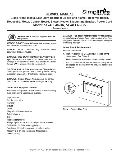
SERVICE MANUALGlass Front, Media, LED Light Boards (Fuelbed and Flame), Receiver Board, Rotisseire, Motor, Control Board, Blower/Heater & Mounting Bracket, Power CordCAUTION! Risk of Cuts, Abrasions or Flying Debris. Wear protective gloves and safety glasses duringinstallation and service. Sheet metal edges are sharp.NOTICE! DO NOT discard this manual. Important serviceand maintenance instructions included.NOTICE! DO NOT discard any hardware while servicing. It may be reused.WARNING! Risk of Shock! Always unplug the cord or turn off the circuit breaker before moving or servicing.Tools and Supplies NeededBefore beginning the installation be sure that the following tools and building supplies are available.Tape measure Needle-nose pliers Hammer Gloves LevelMagnetic Phillips screwdriver Safety glasses DrillFlathead screwdriverPhillips Tip-Bit socket and ratchet (for Blower/Heater)5/16 Drill for 3/16 diameter toggle bolts(applicable if installing on drywall-sheathed walls)Masonry Drill 5/16 in. (applicable if installing on masonry walls)Glass Front ReplacementRemove Glass Front1. Remove the two (2) ST3X8 screws located on theglass panel. See Figure 1. Note: Do not discard screws, screws will be reused. 2. Lift up evenly on the bottom edge of the glass to disengage the J-hooks from the shoulder bolts on the appliance.or property damage.Figure 1. Remove Glass FrontWARNING! Risk of Personal Injury or Property Dam-age! Failure to follow instructions below may result in damage to the equipment and or may expose the user to the risk of 昀椀re, serious injury, illness or death.Stone/Media Installation1. Remove Glass.2. Arrange the stone/media along the inset windowledge at the front of the appliance.Note: Extra media are provided and may bedistributed based on consumer preference. Not all media needs to be used.Glass Replacement (Continued)Installing Glass3. Install front panel. Locate the J-hooks on the back side of the glass on the four shoulder bolts on the appliance opening. Engage the shoulder bolts. See Figure 2.4. Press down on top edge of glass to fully engage J- hooks on the shoulder bolts.Note: Make sure the glass is fully attached to the 昀椀re-box so that the control panel can work properly.Figure 2. Glass Front Removal/Installation5. Thread the two (2) ST3X8 screws into the threaded holes on the glass panel. Check the alignment of the glass panel and securely tighten the screws. SeeFigure 3.Figure 3. Secure Glass Front1. Disconnect electrical service to the appliance. Forrecessed electrical installations that are hardwired,昀椀nd and shut-off service at the breaker. For wall-mounted installations that use a corded plug,disconnect the cord from the receptacle.2. Remove the glass front from the appliance. Use twopeople.3. Remove appliance the two screws in upper right andleft corners of the glass opening. Follow speci昀椀cinstructions from page 1 and 2 for removal of thefront glass. See Figure 4. CAUTION! Two adults recommended for the removal or installation of glass front. Use caution when han-dling glass. Failure to do so could result in personal injuryor property damage. Figure 4. Remove Upper Right & Left ScrewsPreparation for Component Installation4. Remove right and left side panels by turning thepanels inward. See Figure 5.Figure 5. Remove Right & Left Side Panels5. Using a 昀氀athead screwdriver, pry open the seventabs as shown in Figure 6. Pry the tabs upward at a30 degree angle. During this step, take care not toscratch or damage the glass panel behind the tabs.TABSFUELBED PLASTIC COVER Figure 6. Remove Plastic Cover6. Remove the fuelbed plastic cover that covers thefuelbed LED light strips. See Figure 6.LED Light Board InstallationThe LED Service Kit includes LED Light Boards for both the Fuelbed and the Flame effect.Determine which LED light set to be installed. See Figure 7.Figure 7. LED Light Board Identi昀椀cationLED FOR FUELBED1. Complete Steps 1-6 in Preparation for ComponentInstallation instructions. 2. Locate the Fuelbed LED Light Board cable. See Figure 8.LED LIGHT BOARD CABLE3. Unplug the LED Light Board cable. See Figure 9.LED LIGHT BOARD CABLEFigure 8. LED Light Board CableFigure 9. Unplug LED Light Board Cable4. Remove the LED light board from the bottom isolation columns. Starting at one end of the board use aLED FOR FLAMEFigure 10. Isolation Columns5. Remove and discard LED light board, replace with new LED light board. Install new LED light board by engaging the holes in the light board with the plastic barbs, and pressing into position. Reconnect the cables. See Figure 9.Fuelbed LED Light Board InstallationReceiver Board, Rotisseire, Motor, Flame LED Light Board, Control Board and Blower/ Heater Installation1. Complete Steps 1-6 in Preparation for ComponentInstallation instructions.3. Unplug Fuelbed LED Light Board, then lift it from theappliance set aside.Figure 12. Bracket Screw Location4. Remove seven (7) Phillips screws from the bracket. Remove the bracket. Set aside. See Figure 12.5. Carefully remove the glass panel. Rotate the top edge of the glass panel towards the opening, then lift out the the glass panel from the appliance. Set glass panel aside in a safe location, preferably a soft surface such as carpet or cardboard.Figure 11. Fuelbed LED Light Board Screw LocationReceiver Board Installation6. Locate the Receiver Board in the upper right side of appliance. See Figure 13.Figure 14. Receiver Board Cable7. Remove the Receiver Board from the isolationcolumns. Use a needle-nose pliers to compress the barbs on each isolation column.8. Unplug the cable, remove the Receiver Board and install with replacement board. See Figure 14.9. Reverse steps to complete installation.NOTE: The following steps (6-9) are only for re-placement of the Receiver Board.If replacing Rotisseire, Motor, Flame LED LightBoard, Control Board and/or Blower/Heater continue onto step 10.10. Remove two (2) Phillips screws at the bottom of the left and right side of the appliance opening. See11. Remove 14 Phillips screws at the top and bottom of the 昀氀ame screen. See Figure 16.12. Remove the 昀氀ame screen.Note: Be sure to place on a 昀氀at surface with the silk screen face-up. This is to prevent any distortion on the screen.13 Remove the center screw located in the the center of the Rotisseire. See Figure 17.14. Pull the Rotisseire to the left to disengage it from the motor, then remove the Rotisseire assembly.Figure 16. Flame Screen LocationFigure 17. Rotisseire Screw LocationIf replacing only the Rotisseire, install replacement part and reverse the installation steps.Be sure the 昀氀ame screen is installed correctly with the 昀氀ame silk screen to the outside and 昀氀ames at the bottom of the appliance.If replacing Motor continue to the next steps 15-18.Rotisseire InstallationIf replacing Flame LED Light Board continue to step 19.CAUTION! Risks of Cuts! Rotisseire has sharp edgesMotor InstallationThe motor is located in the lower right corner of the appliance.15. Remove the rubber shaft on the motor. See Figure 18.Figure 18. Rubber Shaft RemovalRUBBER SHAFT16. Remove the two screws on the motor. See Figure 19.Figure 19. Remove Motor Screws17. Unplug the motor cable connection. See Figure 20.Figure 20. Unplug Motor Cable18. Install replacement part and reverse the installation steps.Flame LED Light Board InstallationNOTE: The following steps (15-18) are only for re-placement of the motor.If replacing Flame LED Light Board, continue onto step 19.19. Remove screws used to attach the 昀氀ame screenFigure 21. Remove Flame Screen Bracket Screws.20. Remove 昀氀ame screen bracket.21. Unplug cable connection on each end of the LED Board. See Figure 22.Figure 22. Unplug LED Board Cable Connections22. Install replacement part and reverse the installation steps.Control Board Installation23. Remove the two (2) Phillips screws. After removing screws the mounting bracket can be lowered downto access the wires. See Figure 23.Figure 23. Remove Mounting Bracket Screws24. Unplug the 昀椀ve (5) pin and socket connectors between the Control Board and the wire harnesses. Tag and label the wire harnesses to ensure that wires will be reconnected correctly. See Figure 24.Figure 24. Unplug Control Board25. Install new Control Board and reverse the installation steps. Blower/Heater Installation26. Locate the four (4) screws on the mounting plate for the blower/heater module. See Figure 25.27. Remove the four (4) Phillips screws.Figure 25. Remove Mounting Plate Screws28. Drop the Blower/Heater module down on the shelf. See Figure 26.29. Reach up into the right end of the slot, and unplug the cable from the connector.Figure 26. Remove Blower/Heater30. Install new Blower/Heater and reverse the installationsteps.SHELFMasonry Wall •In the marked locations, drill 5/16 in. diameter x 2 in. deep holes. See Figure 30.• Insert the provided wall anchors into the holes. •Gently tap the anchors with a hammer until they are 昀氀ush with the wall surface.•With mounting hooks pointed up, attach the bracket to the masonry anchors with ST5X40 screws . SeeFigure 31.Figure 29. Installing Anchors in Hollow WallFigure 28. Toggle Bolt Installation through Mounting BracketFigure 30. Masonry Anchor PlacementFigure 27. 3/16 Toggle-Bolt Anchor•The toggle-bolt anchors are provided to accomodate the required anchor points based on the appliance. Use of toggle bolt anchors requires drywall thick-ness of minimum 1/2 in. and drilled holes size of 5/16 in. diameter.•Insert the bolt through the front side of the mounting bracket and thread the toggle onto it from the rear of the bracket. See Figure 28.•Fold the toggle wings 昀氀ush against the bolt and push them through a drilled hole until the toggle wings expand open on the other side. See Figure 29. •Pull back on the bolt and tighten. See Figure 29.Note: This product cannot be installed on a wall sheathed with drywall less than 1/2 in. thick, unless all six (6) anchor points in the mounting bracket align with structural framing members.WARNING! Risk of Damage or Personal Injury! Al-lowable pull-out and shear strength are 25% of ultimate values or less, as required by building authorities.Framed Wall •Locate the mounting bracket on the wall in thedesired location of the appliance. Level the bracket, then mark its location on the wall, including a mark-ing for each of the fastener holes in the bracket. •For each of the marked mounting point locations, determine which points align with a structural fram-ing member.•At the points where a wood or metal framing mem-ber exists, the ST5X40 screw can be installed directly into that structural member.•For every mounting hole that does not align with a structural framing member, a wall board toggle-bolt anchor must be used. See Figure 27.Direct Wall Mounting with Wall Mounting BracketThe wall mounting bracket can be installed on masonry walls such as those constructed of brick or concrete, or to framed walls constructed of wood or steel framing sheathed with gypsum wallboard, drywall, wood, etc. The method used to mount the mounting bracket is dif-ferent between masonry walls and framed walls. Refer to the following sections for more detail on the method applicable to this installation.11SimpliFire • SF-ALL48-BK, SF-ALL60-BK Service Manual Rev. B • 2040-960 • 3/18SimpliFire, a brand of Hearth & Home Technologies7571 215th Street West, Lakeville, MN 55044Please contact the SimpliFire customer/technical support hotline at 877-320-0730 with any questions or concerns.WARNING! Risk of Damage or Personal Injury! Do not use supplied masonry anchors on hollow walls,sheathed with wood, gypsum wallbaord, drywall or other materials.Figure 31. Bracket AttachmentWARNING! Risk of Fire, Electrical Shock and Injury! Ensure the power cord is not installed so that it is pinched or against a sharp edge and ensure that the power cord is stored or secure to avoid tripping and snagging.Power Cord Kit InstallationThe appliance power cord has a three pin NEMA-5-15P plug. The power cord should not be used unless a grounded receptacle is available.1. Remove the terminal block cover plate located on the right end of the appliance.2. Disconnect the terminal block from the three wires inside the appliance. Discard the terminal block cover plate.3. Connect the three appliance wires to the terminal block supplied with the power cord kit. See Figure 32.4. Replace cord kit terminal block cover plate and retaining screws. Plug cord into nearest outlet.Figure 32. Optional Power Cord Assembly InstallationLNR E DB L U EWire DiagramY E L L O W / G R E E N。
- 1、下载文档前请自行甄别文档内容的完整性,平台不提供额外的编辑、内容补充、找答案等附加服务。
- 2、"仅部分预览"的文档,不可在线预览部分如存在完整性等问题,可反馈申请退款(可完整预览的文档不适用该条件!)。
- 3、如文档侵犯您的权益,请联系客服反馈,我们会尽快为您处理(人工客服工作时间:9:00-18:30)。
CSRM 型安全继电器模块可实现外部设备监 控功能,自动复位和手动复位功能,2A1B 模块可 实现强制单次复位功能,实现对复位按钮的监控, CSRMB-2A1B 和 CSRMC-2A1B 模块可实现抑制功 能。
(2) CSRM 型安全继电器模块取得了以下认证 EMC 符合证明(测试使用 MW 电源:RS-35-24)
(3) CSRM 型安全继电器模块在设计时考虑了如下 标准 EN/IEC 61496-1(Type 4)
Ⅱ 用户须知
安装、操作或维护 CSRM 型安全继电器模块 前,请务必仔细阅读本使用手册。如有疑问,请向 我公司咨询。
-4-
版权及复制权限 未经许可,不得对本文件进行复制用于销售或
促销。 本文件受版权保护,仅与 CSRM 型安全继电器
模块一起使用。无论因何目的,以何方式复制或转 载本文件之内容完整性。
Ⅲ 安全注意事项
以下特殊信息可能会在本手册的任意地方出 现,用来警告潜在的危险或提示对一些用来阐明或 简化某一程序的信息加以注意。
3.3 接线……………………………………(46) 3.3.1 注意事项 ………………………(46) 3.3.2 接线要求 ………………………(47) 3.3.3 工作电源 ………………………(47)
第 4 部分 检查和调试 …………………………(49) 4.1 安装条件检查…………………………(49) 4.2 上电前接线检查………………………(50) 4.3 功能检查………………………………(51)
- 36 -
a 采用锁螺丝插拔式接线端子 b 采用免锁螺丝可封插式端子台
图 23 CSRM 型安全继电器模块外形尺寸图
- 37 CSRM 型安全继电器模块面板功能如图 24 所 示。
图 24 CSRM 型安全继电器模块面板示例
- 38 -
注:CH1:通道 1 状态指示,当继电器 1 吸合后该指 示灯亮;
CH2:通道 2 状态指示,当继电器 2 吸合后该指 示灯亮;
MUT:抑制状态指示,当抑制信号启动时该指示 灯亮(仅 2A1B 的 B 模块和 C 模块有此功 能);
POWER:电源指示,当继电器模块上电后该指 示灯亮。
- 39 -
1.5 技术参数
ISO 13849-1(PLe)
执行标准 2004/108/EC(EMC 指令)
- 25 图 15 2A1B 监控 PNP 信号-手动复位
- 26 图 16 2A1B 监控 PNP 信号-自动复位
- 27 -
1.3.3 CSRMC-脉冲信号监控 CSRMC 模块可以监控具有脉冲信号输出的安
全光幕输出信号。能监控本公司全系列的安全光 幕——KS02H 型光电保护装置、LDKS-ⅢH 型光电 保护装置以及 KS06 型光电保护装置。以上光电保 护装置配用安全继电器模块时,将不再配用控制 器,光幕的使用详情见对应说明书。CSRMC 模块 采用窄波带滤波设计,中心频率 4kHz,有效避免其 它干扰信号的误触发。配套 KS06 型光电保护装置 时的典型接线如图 17~图 20 所示。确保光幕传输 线的 PE 线良好接地,当机床外壳良好接地时,可将 PE 接于机床外壳。
- 35 -
1.4 外观信息(尺寸说明)
CSRM 型安全继电器模块外形尺寸如图 23 所 示,可提供两种插件端子,图中 a)所示为采用锁螺 丝插拔式接线端子的外观示例,图中 b)所示为采 用免锁螺丝可封插式端子台的外观示例,产品标配 为采用锁螺丝插拔式接线端子,免锁螺丝可封插式 端子台成本较高,产品价格会有差异,若有需要请 在订货时咨询市场销售人员,并在采购合同中进行 说明。
- 19 图 9 3A1B 监控 NPN 信号-手动复位
- 20 图 10 3A1B 监控 NPN 信号-自动复位
- 21 图 11 3A1B 监控 PNP 信号-手动复位
- 22 图 12 3A1B 监控 PNP 信号-自动复位
- 23 图 13 2A1B 监控 NPN 信号-手动复位
- 24 图 14 2A1B 监控 NPN 信号-自动复位
-6-
Ⅳ 安全使用注意事项
为确保 CSRM 型安全继电器模块的安全使用, 请务必遵守以下注意事项。
在使用 CSRM 型安全继电器模块前,仔细阅读本 手册,了解安装,操作检查及维护的要求。 CSRM 型安全继电器模块应当由专业人员进行 安装、检修和保养。 专业人员是指经过专业培训并取得认可资格的 人员,或者有着丰富的知识、培训和经验且已经 被证明拥有解决此类问题能力的人员。 OSSD 必须满足以下条件: OSSD 不可在外部短接; OSSD 所带负载不应超出额定值。 不可跌落 CSRM 型安全继电器模块。
1.3.1 CSRMA-两路常闭开关监控 ………………………………………(9)
1.3.2 CSRMB-两路晶体管信号监控 ……………………………………(18)
1.3.3 CSRMC-脉冲信号监控 …………(27) 1.3.4 CSRMD-双手按钮监控…………(32) 1.4 外观信息(尺寸说明)…………………(35) 1.5 技术参数………………………………(39) 第 2 部分 功能介绍 ……………………………(42) 2.1 安全自检功能…………………………(42) 2.2 外部设备监控功能……………………(42) 2.3 复位功能………………………………(42) 2.4 抑制功能………………………………(43) 第 3 部分 安装、接线 …………………………(44) 3.1 安装条件………………………………(44) 3.2 安装方法………………………………(45)
1.2 规格型号
-9-
注:3A1B 模块和 B 型模块的工作电压为 DC24V,2A1B 的 A/C/D型模块的工作电压为AC/DC24V
1.3 应用说明
1.3.1 CSRMA-两路常闭开关监控 CSRMA 模块可用于监控两路常闭开关信号如
急停按钮、安全门开关等。可对两路信号间的短路 进行监控,当两路输入信号短路时模块电源掉电,
- 13 图 4 3A1B 监控急停信号-自动复位
- 14 图 5 2A1B 监控安全门信号-手动复位
- 15 图 6 2A1B 监控安全门信号-自动复位
- 16 图 7 2A1B 监控急停信号-手动复位
- 17 图 8 2A1B 监控急停信号-自动复位
- 18 -
1.3.2 CSRMB-两路晶体管信号监控 CSRMB 模块用于监控两路 PNP 信号或 NPN 信
第 5 部分 维护 …………………………………(55) 5.1 受控设备检查…………………………(56) 5.2 每 6 个月或设备配置变化时检查项 …………………………………………(56)
第 6 部分 故障诊断 ……………………………(57)
-1-
Ⅰ 指令与标准
(1) CSRM 型安全继电器模块符合下列标准 ISO 13849-1(PLe) 机械安全指令 2006/42/EC EMC 指令 2004/108/EC
目录
Ⅰ 指令与标准 ……………………………(1) Ⅱ 用户须知 ………………………………(1) Ⅲ 安全注意事项 …………………………(4) Ⅳ 安全使用注意事项 ……………………(6) 第 1 部分 产品介绍 ……………………………(8) 1.1 产品概述 ………………………………(8) 1.2 规格型号 ………………………………(9) 1.3 应用说明 ………………………………(9)
控到双手按钮均被触发后控制输出闭合。模块具 有按钮信号一致性检测能力,当双手按钮触发时差 大于 0.5s 时,视为无效触发。模块采用双回路工 作、全回路自检,当两路信号不一致时进行锁定。 其典型接线如图 21 和图 22 所示。
- 33 图 21 3A1B 监控双手按钮信号
- 34 图 22 2A1B 监控双手按钮信号
号,例如光电开关、安全光栅等。模块也可配合外 围电路,实现对两路常闭开关信号的监控。模块采 用双回路工作、全回路自检,当两路信号不一致时 进行锁定。CSRMB 模块拥有强大的晶体管残压信 号适应能力,残压大于 10V 时仍能稳定工作。典型 接线见图 9~图 16。配合光栅使用时,确保光栅传 输线的 PE 线良好接地,当机床外壳良好接地时,可 将 PE 接于机床外壳。
2006/42/EC(机械安全指令)
参考标准 EN/IEC61496-1(Type 4)
环境温度 环境湿度 防护等级
工作 存储 工作 存储 IP50
-10~55℃ -30~70℃ 35%~85%RH 35%~95%RH
抗振动能力
频 率 10~55Hz,振 幅 0.35 ± 0.05mm,X、Y 及 Z 方向各 20 次
若客户未按本手册的要求操作而引起的任何 损害、损失及风险,本公司不承担任何责任。
本公司只针对产品在被正确的操作、储藏、安 装和维护的条件下所出现的质量问题进行维护或
-3-
更换。经公司技术人员检测确认符合以上条件且 产品没有受到污染、滥用、误用或不当的改造或维 修,我公司将按产品订购合同的规定为使用客户提 供优质的售后服务。
规格变更 产品规格和配件可能随时会基于改进或其它
原因而改变。 当产品的性能、参数或结构改变时,产品的规
格型号会随之改变。对于产品规格型号的变更, 我 公 司 不 会 另 行 通 知 ,如 有 疑 问 ,请 向 我 公 司 咨 询。
错误和遗漏 在编制本说明书过程中已经力求内容的正确
与完整,但并不保证本说明书没有任何错误或疏 漏。若发现问题,敬请提出,以便及时更正。
- 10 若发现模块所有指示灯均不亮时,请检查其两路输 入信号是否存在短路的情况。模块对任意单一开 关短路、断路故障进行监控,当开关不一致时锁定 到安全状态。其典型接线方式见图 1~图 8。