合金钻头的选用
合金钻头的倍径

合金钻头的倍径一、引言合金钻头是一种常用的工具,用于在不同材料上钻孔。
而合金钻头的倍径是指在钻孔过程中,钻头直径与孔径之间的比值。
合金钻头的倍径对于钻孔质量、工作效率以及工具寿命等方面都有着重要的影响。
本文将从不同角度探讨合金钻头的倍径对钻孔过程的影响,以及如何选择合适的倍径。
二、合金钻头的倍径对钻孔质量的影响2.1 钻孔直径与合金钻头倍径的关系在钻孔过程中,合金钻头的直径与钻孔直径密切相关。
合金钻头的倍径越小,钻孔直径也越小,反之亦然。
合金钻头的直径与钻孔直径之间的匹配程度对钻孔质量有着直接的影响。
2.2 合金钻头倍径对钻孔的精度要求钻孔的精度对于很多应用来说是至关重要的,尤其是在需要精确安装零部件或进行配合时。
合金钻头的倍径与钻孔精度之间存在一定的关联。
当合金钻头倍径与钻孔直径匹配良好时,钻孔的精度可以得到有效控制。
2.3 合金钻头倍径对钻孔表面质量的影响合金钻头的倍径还会对钻孔的表面质量产生影响。
当合金钻头倍径过大时,钻孔表面容易产生毛刺、裂纹等缺陷,从而降低钻孔的质量。
因此,选择合适的合金钻头倍径对于保证钻孔表面质量是至关重要的。
三、合金钻头的倍径对工作效率的影响3.1 合金钻头倍径与钻孔速度的关系合金钻头的倍径对钻孔速度有一定的影响。
一般来说,合金钻头倍径越大,钻孔速度越快。
然而,过大的倍径可能导致钻孔过程中的振动增加,从而影响工作效率。
3.2 合金钻头倍径与钻孔力的关系合金钻头的倍径也会对钻孔力产生影响。
倍径越大,钻孔力越大。
因此,在实际应用中,需要根据具体的材料和工艺要求选择合适的合金钻头倍径,以确保钻孔力的合理控制。
3.3 合金钻头倍径对工作寿命的影响合金钻头的倍径还会对工具的寿命产生影响。
倍径过大会增加钻头的磨损和热量积累,从而缩短工具的使用寿命。
因此,在选择合金钻头倍径时,需要综合考虑工作效率和工具寿命的平衡。
四、如何选择合适的合金钻头倍径4.1 根据钻孔要求确定合金钻头倍径范围根据具体的钻孔要求,可以确定合金钻头倍径的范围。
高速钢钻头及硬质合金钻头切削用量的选用

加工材料钻头直径(ød)切削速度V(m/min)进给量f(mm/r)进给速度F(mm/min)加工材料钻头直径(ød)切削速度V(m/min)进给量f(mm/r)进给速度F(mm/min) 623.60.11251075.40.15360 825.50.121221589.50.18342 1025.10.1411220103.60.22363 15260.189925117.80.25375 2025.50.2289301130.28336 25240.2576351040.3285 30220.286540100.50.33264 35200.35540190.35531062.80.2400 45170.42501584.80.22396 60150.5402094.20.25375251020.28364 620.70.151653094.20.3300 823.90.21903593.40.33280 1023.60.261954087.90.35245 1525.90.321762025.10.381522527.50.421473026.40.481343519.80.529440150.55664514.10.6606014.10.65492. 对孔的精度要求较高或孔表面粗糙度要求较高时,内冷充分冷却。
高速钢钻头的切削用量(推荐值)铸铁(HB120~225)硬质合金钻头的切削用量(推荐值)碳素结构钢和优质碳素结构钢(HB125~225)铸铁(HB120~225)注:1. 以上切削参数使用条件:孔深=3ød;硬质合金钻头 可适当提高转速,降低进给量。
碳素结构钢和优质碳素结构钢(HB125~225)钻头直径mm 15φ< 30~15φφ< 50~30φφ<进给量 mm/r0.05~0.15 0.15~0.25 0.20~0.30硬质合金钻头线速度 min /120~100m =ν高速钢钻头(HSS) 1> Q235-A min /30m =ν 2> 16Mn min /20m =ν切削速度ν:刀类相对于工件的线速度转速即圆周长ו•=n d πν高速钢钻头线速度:min /03~25m =ν进给量(吃刀量)mm/r 钻头每转一转走的长度(轴向),取:0.2mm/r(齿数)刃Z /×mm 取0.1~0.2 mm/刃硬质合金钻头线速度min /120~100m =ν孔的精度:孔径公差;孔的表面光洁度 钻孔精度:孔距公差;孔的垂直度THE TWIST DRILLSThe twist drill is the more simple tool for drilling holes cylindrical, usually from solid.The twist drill is formed by:x by a cylindrical or conical shank to center on the spindle of the machine and transmit the cutting torque (by friction or drag tooth)x by a cylindrical part in which are carried two opposing helical grooves, which intersect with surface ends form the two main cutting edges.The two helical grooves allow the evacuation of the chip that is formed at the cutting edges, and lead near the same, the lubricating/coolant fluid .Characteristic elements of endsThe check or driving surfaces (with rake angle lower by about 2°) are formed by two off-set diametrically opposed to the limit of the helical grooves and have a dual function: à driving the tip into the hole without even the jam during drilling, because thecontact between the drill and sides of the hole is limited.à finishing the cylindrical surface of the hole.The central core (central scraping edge) between the two grooves has a diameter (0.1~0.2) × D and provides to give the torsional strength to the drill during machining. However for a hole made by a twist drill we can be obtained the maximum standard ofIT 10 and a roughness Ra> 1.8 mm, which often must be finished with other processes such as boring or grinding.Caracteristic anglesİ :Inclination angle of helix .It is formed ythe tangent of the helix average with axisof the drill. Its value is so smaller as harderSEZ N-Nis the material to machining.ij:Angle of cutters. It is the angle formedby the two main cutter.Ȗ:Upper rake angleȕ:Cutting angleĮ:Lower rake angleThe characteristic angles can assume different values in according to the material to be machined and the diameter of the drill.WORKING CONDITIONS IN DRILLINGRelative motion and cutting parametersThe main relative motions are the motion of cutting and the move of advance or feed. The motion of cutting is the main motion of the machine, and is what determines the removal of chip.On the drilling machine it is rotating type and is acted by the tool.The motion of cutting can be expressed both as cuttingspeed, both as rotary speed.The cutting speed, denoted by V (m / min), represents therelative speed between tool and workpiece, at the pointwhere it be removed the chip, therefore the speedwherewith the material can be cut.It is equivalent to peripheral speed of the tool, that is thespeed of point P shown in the figure, which is tangent tothe circle of point P in same sense of rotation. The cuttingspeed is not constant along all points of the cutting edge,but varies from a maximum (cutting speed rated) at thepoint P to a zero value at the axis of the tool.The value set depends on: material processing, material ofthe tool and diameter of the drill.There are tables indicating the value needed depending onworking conditions.The cutting speed and the speed of rotation are related by:This relation calculates the number of rounds to select on the drilling machine, after determining the cutting speed more suitable for processing.The movement of advance or feed aims to bring new material from the tool contact. It is a movement much slower than the motion of cutting.On drilling machine it is a translational motion and is impressed to the tool, according to its axis, in a continuous and simultaneous movement of the cutting.The movement forward can be expressed as feed per revolution, both as speed of advancement.Advancement per revolution, indicated by a (mm / rev), representing the movement of the tool for every lap completed by the same tool.Its value depends on the diameter and material of tool, as well as the material processing. For the selection of the advanced exist tables that suggest the value needed depending on conditions of work.Speed of advancement, indicated by Va (mm / min), represents the speed with which the tool moves, hence the speed with which the processing proceeds.The two magnitude are related by the following relation:Indeed, if a indicates the tool displacement per revolution, multiplying its the number for the revolutions n made in a minute, you get the movement of the tool for each minutes; that is its speed of advancement.SECTION OF THE CHIPThe section of the chip, denoted by q, in the case of a twist drill,takes the form of a parallelogram equivalent to a rectangle ofheight equal to half of the feed per revolution and a basis equalto the radius of the drill. (D / 2 represents the depth of cut in thecase of drilling a hole from solid).Indeed, if for every round of the drill advances of a step equal to a(advancement per revolution), each of cutters to remove a chipwith a side a / 2.In this case, the section area of the chip removed from each edge is:Cutting forceCutting forces required on both edges of the twist drill to detach the chip depend :x from material of workpiece, through the load or pressure to tear Ks (N/mm2).x from total chip section Q = 2 x q (mm 2) detached from the tool.These forces, one for each main cutting edge, supposedly applied approximately half the length of the cutting edge.Each of them takes the value:section of one cutter chipthere is a cutting force :withThen foreach cutterOn average it is considered that : xKs = (4,2 y 5) Rm for cast ironwitch Rm the diameter of drill nd with higher values he total cutting force is :x Ks = (4,8 y 6) Rm for steels and non-ferrous materials In is strength of the material in N/mms decreases with increasing of the advanced. However keep in mind that the value of K a TCUTTING POWERcreate a torque (cutting moment). with dimension b in metres.Looking where the cutting forces are positioned you can see that they form a couple of forces that The value is:aller values forrittle materials (cast iron), higher values for lasting materials (steel).sional stress, where the torque is equal and opposite to the utting moment.sics we know that in rotary motion, the power is calculated using the followinglation:The value of arm b is assumed, the approximate equivalent to D / 2, but in reality its value varies with the type of material that is drilled. In particular b = (0.45÷ 0.60) × D : sm b The tool is subject to a tor c From phyre Where M is sum of torques applied to the body respect to its axis of rotation. nd Ȧ is the angular velocity of the body. the case of drilling:xM represents the moment of cutting forces, then as we saw earlier.with dimension b in metresxȦ is the angular velocity of twist drills.with n number of rounds of the drill ino the cutting power is:aInSWhereand :he power required for the advancement of twist drills can be neglected, because little. tearing of the chip, but also all the sses may be present in transmission of motion.o account for this power dissipation introduces the mechanical efficiency: echanical efficiencyom which flows: T So that the processing is possible, the engine power of the drill must be capable of winning not only the moment of resistance due to lo T m fr that allows us to calculate the engine outputen we known the effective power of cutting and the mechanical efficiency of the achine.he mechanical efficiencyȘ depends on the state of the machine: h = 0.6 ¸ 0.8. power, wh m T It has the condition of maximum utilization of the drilling machine when the power eveloped by its motor c Working timedoincides with the available power of the engine.The relation that calculates the working time is the following:he tool, is With reference to the figure we see that the travel,that is the distance that who must run t e sum of four quantities, namely:th L is the depth of the holee 1 is the overtravel attack : e 1 = 1÷ 2 mm e 2 is the overtravel output : e 2 = 1 2 mml p is the height of the drill cone : l p = ~ 0.33 × DRegarding the height of th edges, with the following considerations of trigonometry.angle OAB is noted that:e drill cone, the approximate value lp = ~ 0.33 × D, can bereplaced by the correct value function of the cuttingFrom the tri from the definition of tangent:which is calculated:For example in the case of a twist drillø 20 for drilling steel with Rm <700 N/mm2 withngle of the cutting edges M = 118 ° is calculated:aE XEMPLEecessary power and time to drill a trough hole ( Tool in high speed steel ) eatures:nd N/mm 2Mechanical efficiency Ș = 0,75alculation of poweralculation of working timeel with Rm <700 N/mm2 and with angle of thecutting edges M = 118°, it is calculated:N F Hole diameter D = 16 mm Hole deep L = 25 mm Feed a = 0,2 mm/rou Cutting speed V = 32 m/min Material strength Rm = 600C We can assume:We think to can select exactly this speed on drilling machineCutting powerOutput power of motorC If we use a twist drillø 20 for drilling ste We assume。
钻头选择和使用
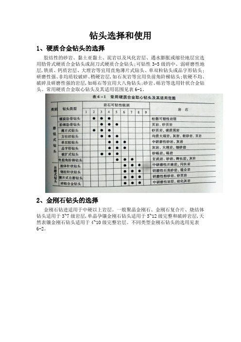
钻头选择和使用1、硬质合金钻头的选择胶结性的砂岩、黏土亚黏土、泥岩以及风化岩层、遇水膨胀或缩径地层宜选用肋骨式硬质合金钻头或刮刀式硬质合金钻头;可钻性3-5级的中、弱研磨性地层,铁质、钙质岩层、大理岩等宜用直角薄片式钻头、单双粒钻头或品字形钻头;研磨性强、非均质较破碎、稍硬岩层,如石灰岩等宜用负前角阶梯钻头;软硬不均、破碎及研磨性强的岩层,如砾石等宜用大八角钻头;砂岩、砾岩等选用针状合金钻头。
常用硬质合金取心钻头及其适用范围见表6-1。
2、金刚石钻头的选择金刚石钻进适用于中硬以上岩层。
一般聚晶金刚石、金刚石复合片、烧结体钻头适用于3~7级岩层,单晶孕镶金刚石钻头适用于5~12级完整和破碎岩层,天然表镶金刚石钻头适用于4~10级完整岩层。
不同类型金刚石钻头的选用见表6-2。
金刚石钻头主要参数及结构要素与钻头选择如下:(1)钻头唇面形状。
中硬、中等研磨性的岩层,宜选用平底形唇面或圆弧形唇面;坚硬且研磨性高的岩层,可用半圆形唇面;对复杂、破碎不易取得岩心的地层,可选用阶梯底喷式唇面;坚硬、致密易出现打滑的岩层,可选用锯齿形唇面。
金刚石取心钻头唇面形状及适用地层参见表5-29。
(2)胎体硬度。
岩石的研磨性越强或硬度越低,则钻头胎体的硬度应越髙;反之,岩石的研磨性越弱或硬度越高,则钻头胎体的硬度应越低。
不同岩层推荐胎体硬度及耐磨性参见第5章表5-35。
(3)金刚石浓度。
岩石硬度越高或研磨性越弱,则钻头金刚石浓度应越低;反之,岩石硬度越低或研磨性越强,则钻头金刚石浓度应越髙。
人造孕镰金刚石钻头在不同岩层推荐的金刚石浓度值参见表5-39。
(4)金刚石粒度。
若石的研磨性越强,硬度越高,则要求钻头的金刚石颗粒应越小,最好用孕镶钴头;岩石硬度越低,研磨性越弱,则要求钻头的金刚石夥粒应越大。
孕镶金刚石钻头推荐粒度参见表5-40,表镶金刚石钻头推荐粒度参见表5-41。
3、钻头的合理使用(1)按照相关标准严格检查钻头与扩孔器,将符合要求者按钻头与扩孔器外径先大后小的次序排队编组轮换使用,同时亦应先用内径小的,后用内径大的在轮换过程中,应保证排队的钻头、扩孔器都能正常下到孔底,以避免扫孔残留岩心。
钛合金钻孔技巧

钛合金钻孔技巧:
钛合金钻孔有以下技巧:
1.选择适合的钻头:钛合金是一种较为坚硬的材料,需要专门的钻头进行钻孔,比如
硬质合金钻头、纳米涂层钻头等。
2.控制转速和进给:在钛合金的钻孔过程中,适当的转速和进给是非常重要的。
太慢
的转速会导致钻头容易磨损,不能顺利穿过工件;太快的转速又容易出现锋利的切屑,容易为工件带来一定的风险。
建议一开始时慢慢逐渐加快,待钻头穿过后一定要及时清洁切削面和刀塞,避免出现太快转速或进给导致的高热问题。
3.使用冷却润滑剂:在钻孔过程中使用一定的冷却润滑剂,可起到降温、减少钻头与
工件之间的摩擦、延长工具寿命等效果。
建议使用硫化油、切削液等,加强冷却润滑效果。
钻头材质图图层颜色与用途

钻头材质图图层颜色与用途钻头材质是决定钻头耐磨性、切削性和散热性能的重要因素之一。
根据不同的应用场景和需求,钻头常使用不同种类的材质来制造。
对于不同的钻头材质,其图层颜色和用途也会有所区别。
下面将会详细介绍几种常见的钻头材质、图层颜色以及它们的用途。
1. 高速钢(高硬度合金钢):高速钢是一种优质的钻头材质,通常颜色为灰色或深灰色。
由于高速钢具有较高的硬度和强度,适用于切削大多数的金属材料,如钢、铝、铜、铁等。
高速钢钻头可以在高温和高速的工作环境下保持其硬度和刚性,因此在工业中应用较广泛。
2. 硬质合金:硬质合金钻头的图层颜色主要是钨钢色,即灰色或黑色。
硬质合金通常是由钨钴和其他金属粉末经过高温压制、烧结和砂轮修整而成。
硬质合金钻头具有优异的切削性能和耐磨性,适用于加工硬质材料如铸铁、不锈钢和钛合金等。
硬质合金钻头在很多领域都有应用,如航空航天、汽车制造、机械加工等。
3. 镀钛钻头:镀钛钻头是一种常见的表面处理技术,用于提高钻头的耐磨性和延长使用寿命。
其图层颜色通常是金黄色。
镀钛钻头由高速钢或硬质合金基体经过表面处理工艺,将一层薄膜的钛合金沉积在钻头表面,从而提高钻头的硬度和耐磨性。
镀钛钻头适用于切削各种材料,特别是耐高温材料,如铸铁、不锈钢和钛合金等。
4. 钻石钻头:钻石钻头是一种高级的切削工具,其图层颜色为金黄色或透明色。
钻石是一种天然的超硬材料,具有极高的硬度和耐磨性。
钻石钻头适用于高硬度材料或非金属材料的加工,如陶瓷、玻璃、岩石、大理石等。
由于钻石钻头的价格昂贵,因此一般适用于特殊的领域,如珠宝、切割工具等。
除了上述提到的几种常见的钻头材质,还有其他一些特殊材质的钻头,如碳化硅钻头、陶瓷钻头、纳米复合涂层钻头等。
这些钻头材质在特定的应用领域中具有独特的优势和适应性。
总结起来,钻头的材质图层颜色与其用途密切相关。
高速钢钻头适用于切削大多数金属材料;硬质合金钻头适用于切削硬质材料;镀钛钻头适用于提高耐磨性和延长使用寿命;钻石钻头适用于切削高硬度或非金属材料。
钻头的选用方法

2 .焊接硬质合金钻头
焊接 硬质 合金 钻 头 是 在 钻 柄 螺 旋 槽 的尖 端 ,焊 接上 一块硬 质 合 金 钻 尖 ,如 图 4所 示 。钻 尖 可 多次 重磨 ,刀具 成 本 低 于 整体 硬 质 合 金 钻 头 ,适 用 于直
性 夹套 ,故 刀柄 成 本 略 低 。侧 固刀 柄 定 位 精 度 略 低 于 圆柱 柄 ,适 用 于加工 孔 的精 度为 I9 1 。特 别 T ~ 0级
图 4 焊接 硬质合 金钻 头
心 ,中心刀 片过 中心 内刃 钻 出 1 8 锥 面 ,可 引 导 钻 2。 轴 不偏 。外 刀片 刀刃安 装 出 8 。 9 主偏角 ,形成 了 1 8 7。 顶 角 ,径 向力 极 小 ,同时 形 成 了 1 的 副偏 角 。主 副 。 刀 刃转 角处 有 圆弧 刃 相 连 有 利 于修 光 。可 转 位 刀 片 钻 头可用 的切 削参 数 为 V=10~10 / i 、厂 . 8 2 5 m r n =0 0 a
图 8 可转位刀片钻头 的钻镗功能
4 .可 转 位 刀 片 钻 头 可 转位 刀 片 钻 头 也 称 可 转 位 浅 孔 钻 、u 形 钻 , 适 合用 于 L D< / 5的 中等直 径 孔加 工 ,可 在 车床 、钻 床 上使 用 。如 图 6所 示 ,可 转 位 刀 片 交 错 分 布 在 钻
0 1 m / ,钻孔效 率较 高 。 .8 m r
称 刀头 ) 与 刀体 用 圆
柱 头 定 位 ,弹 性 加 紧
2 。 6
方 式 连 接 ,更 换 方
6 9
便 ,重 复 定 位 精 度 较 高 ,加 工 精 度 可 达 I8级 。一 支 钻 体 可 T 配用 1 mm范 围 内的不 同尺 寸 的 刀 头 ,并 能 多次 更 换 刀 头 重 复 使
5个硬质合金钻头标准
硬质合金钻头标准包括以下5个方面:
1. 材质:硬质合金钻头通常采用高硬度的钨钴钛合金制成,这种材料具有优异的耐磨性和切削性能。
2. 钻头直径:硬质合金钻头的直径应根据具体的应用场景和需求进行选择。
通常,直径越大,钻头的强
度和切削能力也越强。
3. 钻头长度:硬质合金钻头的长度也应根据具体的应用场景和需求进行选择。
一般来说,长钻头适用于
深孔加工,而短钻头适用于浅孔加工。
4. 钻头角度:硬质合金钻头的角度包括顶角、后角和螺旋角等。
这些角度的设计应根据具体的材料和加
工要求进行选择,以保证切削效果和钻头的寿命。
5. 涂层:为了进一步提高硬质合金钻头的性能和使用寿命,通常会对其进行涂层处理。
涂层材料通常为
氮化钛、碳化钛等,这些涂层可以提高钻头的硬度、润滑性和抗热性能。
总的来说,硬质合金钻头标准应根据具体的应用场景和需求进行选择和设计,以保证其性能和使用寿命。
此外,为了确保钻头的质量和性能符合要求,还需要进行相关的检测和认证。
电钻铝合金打孔技巧
电钻铝合金打孔技巧
使用电钻时,铝合金是一种常见的材料。
然而,由于其特殊的物理性质,铝合金在钻孔过程中可能会造成一些问题,如断钻、生锈和过度加热。
以下是一些钻孔铝合金时应注意的技巧:
1. 选择合适的钻头。
对于铝合金,建议使用高速钢钻头或钴钢钻头。
这些钻头的硬度和刚度较高,适合钻孔硬度较高的材料。
2. 保持冷却。
铝合金的导热性很好,容易在钻孔过程中过热。
因此,在钻孔时要保持冷却。
最简单的方法是用润滑油或冷却液涂抹在钻头上,以减少摩擦热。
3. 控制钻头速度。
钻孔时,钻头的旋转速度应适当。
如果速度太慢,则会增加摩擦力和热量,导致过度加热,烧毁钻头。
如果速度太快,则会破坏铝合金表面。
4. 使用适当的力量。
在钻孔过程中,适当的力量是至关重要的。
如果用力过猛,则会导致钻头断裂;如果用力不足,则会增加摩擦力,导致钻头过度加热。
5. 选择正确的钻孔位置。
钻孔位置对钻孔质量也有重要影响。
建议在铝合金较厚的部分进行钻孔,以减少振动和降低断钻的风险。
通过采用上述技巧,我们可以更加有效地钻孔铝合金,避免一些常见问题的出现,提高工作效率和质量。
- 1 -。
铝合金钻孔加工钻头如何选择
铝及其合金,由于密度小并具有一定的机械加工性能和良好的导电性、导热性及耐蚀性,因此在各种工业部门中都得到广泛的应用,特别是航空领域。
但在钻孔加工中,铝合金却存在着很多的加工难题。
铝合金按制造方法不同,分为铸造的和形变(可压延)的两大类。
形变铝合金多用来制造拉伸的零件、铆钉、板材、型材等,这一类零件在加工过程中,孔的加工并不多见,我们暂且不考虑。
而铸造铝合金,相对而言种类很多,最基本的是铝硅合金是硅铝明。
01与钢材和黄铜相比,铝合金的特点:一是材质软,刚性差二是弹性模量低。
这两个因素显著影响了铝合金的切削加工性。
因此,在加工铝合金工件时,必须充分地夹紧和支撑工件,并保持刀具锋利。
否则,工件往往会有离开切削刀具的倾向。
有时工件的表面出现不规则的槽痕和光亮的挤压斑,一种可能是由于刀具对工件的压力不正常引发的,还有一种可能是由于夹持不牢固而引起振颤时,刀具在工件的表面作间隙式的磨蹭,发生挤压现象和粉状切削,然后当间隙或弹性消失时,刀具就咬入工件的表面,啃出槽痕。
所以,在钻孔过程中,我们也要注意铝合金的切削要点,合理地选取铝合金的切削方法。
02选择铝合金群钻在钻削过程中,标准群钻由于外刃锋角(2Φ)、内刃锋角(2Φ')相对较大,后角(α)较小,后刀面与被切削面摩擦严重,产生了大量的切削热,切削温度升高快;主切削刃对材料的切入角小,切削厚度变薄,容易碎断,不易排出;内刃前角为负值,工作中完全处于挤压切削状态,局部温度高,材料融敷现象严重。
铝合金专用群钻几何参数和形状的改进。
经过长期实践,我们对标准群钻进行了几何参数和形状上的改进,刃磨成铝合金专用钻头,将原有140°的外刃锋角减小至105°~110°,这样就减少了轴向力,加大了刀尖角,改善了散热条件,加剧了切屑变形,形成了条状切屑。
加大后角,将后角α由原来的13°~14°加大至22°~23°,这样就减少了切削热的产生,使熔敷现象减轻,同时较大的后角,也使得主切削刃更加锋利,容易切入材料,形成厚切屑,方便排出。
钻头选择和用法
钻头选择和用法钻头是钻孔的重要工具,选择适合的钻头可以提高工作效率和质量。
本文将介绍钻头的选择和使用方法,希望对大家有所帮助。
一、钻头的选择1. 钻头的材质不同材质的钻头适用于不同的工作材料。
钻头的材质有高速钢、硬质合金、钻石等。
高速钢钻头适用于钻软质材料,硬质合金钻头适用于钻硬质材料,而钻石钻头适用于超硬材料的钻孔。
2. 钻头的直径钻头直径的选择应该根据钻孔的要求和工作材料的硬度来决定。
对于较硬的材料,需要选用较小直径的钻头,而对于软质材料可以考虑选用较大直径的钻头。
3. 钻头的长度钻头的长度应该根据钻孔深度来选择。
过长的钻头容易折断,过短的钻头不能钻到预期位置。
4. 钻头的形状钻头的形状有直柄、圆柱、锥形等多种形式。
不同形状的钻头适用于不同的钻孔场合。
例如,锥形钻头可以在不同直径的孔中钻出适合的孔洞,而圆柱形钻头可以钻出标准大小的孔洞。
二、钻头的使用方法1. 钻孔前的准备在钻孔前,应该仔细检查钻头的状态。
如果钻头有损伤或磨损,应该更换新的钻头。
同时,需要选用适合的冷却液,在钻孔时往钻孔位置不断滴入冷却液,以保持钻头的清洁,避免过热和磨损。
2. 钻孔时的操作(1)确定钻孔位置和深度。
(2)将钻头与钻机卡口紧固,开启钻机。
(3)将钻头缓慢地放到工作材料上,施加适当的力量,使钻头慢慢进入材料。
要注意钻孔过程中的速度和力度,不要过快或过慢,避免钻头折断或损伤工件。
(4)如钻头进入物料后未见钻头硬度,则需加压,直至水平位置的手掌如果觉得发热uc0一定要停下来,冷却后再继续。
(5)钻孔完成后,应该用冷却液清洗钻头,并及时清理工作面,以免影响下一次钻孔质量。
三、注意事项1. 钻头使用前,应该先检查其是否完好,避免造成损害。
2. 钻头必须保持冷却,以保证钻头的寿命和工作效率。
3. 钻孔时应该使用适当的加压力度,不要过急或过缓。
4. 钻孔完成后应该及时清洗和保养钻头,避免生锈和损坏。
总之,选择合适的钻头和正确的使用方式,不仅可以提高工作效率,还能够保证钻孔质量。
- 1、下载文档前请自行甄别文档内容的完整性,平台不提供额外的编辑、内容补充、找答案等附加服务。
- 2、"仅部分预览"的文档,不可在线预览部分如存在完整性等问题,可反馈申请退款(可完整预览的文档不适用该条件!)。
- 3、如文档侵犯您的权益,请联系客服反馈,我们会尽快为您处理(人工客服工作时间:9:00-18:30)。
密级:秘密版本/更改状态:第一版/0
编号:
长城汽车股份有限公司技术文件
合金钻头的选用
技术分析报告
编制:
审核:
审定:
批准:
长城汽车股份有限公司传动事业部
二〇一一年六月
合金钻头的选用
[摘要]人们一向认为钻削加工必需在较低的进给量和切削速度下进行,这种概念在使用通俗钻头的加工前提下曾经是切确的。
现在,随着硬质合金钻头的出现,钻削加工的概念也发生了转变。
选用合适的硬质合金钻头,可以大幅度提高钻削加工效率,降低每孔加工成本。
[关键词] 钻削加工硬质合金孔加工成本
整体硬质合金钻头适于先进的加工中心上。
这种钻头采用细颗粒
硬质合金材料制造,为延长使用寿命,还进行了TiAlN涂层,专门设
计的几何刃型使钻头具有自定心功能,在钻削工件材料时具备精准的
切屑节制及排屑机能。
该钻头的自定心功能和严酷节制的制造精度可
确保孔的钻削质量,钻削后不需再进行后续精加工。
一、硬质合金钻头的类型
(1)整体硬质合金钻头。
这种钻头一般直径较小,因为硬质合金材
料价格昂贵,而钻头的有效部分最多占整体刀具的二分之一,其它部
分不能产生价值。
为了减少浪费所以一般的整体合金钻头直径都比较小。
我司的整体合金钻头最大直径为20mm。
(2)硬质合金可转位刀片钻头
安装硬质合金可转位刀片的钻头可加工孔径规模很广,加工深度规模
为2D~5D(D为孔径),可应用于车床和其它扭转加工机床。
这种钻
头的可刃磨性差且加工精度较低所以这种钻头在我司极少应用。
(3)焊接式硬质合金钻头
焊接式硬质合金钻头是在钢制钻体上平稳焊接一个硬质合金齿冠制成。
这种钻头采用自定心几何刃型,切削力小,对工件材料可实现精
准的切屑节制,加工出的孔概况光洁度好,尺寸精度和定位精度都很高,不必再进行后续精加工。
该钻头采用内冷却,可用于加工中心、CNC车床或其它高刚性、高转速机床。
这种钻头价格比整体合金钻头
较低可以大量采用。
但是刃磨的时候需要注意:因为合金是焊接在钢制钻体上的,而刃磨合金和刃磨钢体的砂轮材质不同但是这两种材料是焊接在一起中间很难分清楚所以刃磨的时候一定要小心,注意刃磨量否则会损坏砂轮。
(4)可改换硬质合金齿冠钻头
可改换硬质合金齿冠钻头是近年开发的新一代钻削刀具。
它由钢制钻体和可改换的整体硬质合金齿冠组合而成,与焊接式硬质合金钻头对比,其加工精度半斤八两,但因为齿冠可改换,是以可降低加工成本,提高钻削出产率。
这种钻头可获得切确的孔径尺寸增量并具有自定心功能,是以孔径加工精度很高。
可改换硬质合金齿冠钻头一般不能刃磨但是在考虑每孔加工成本时,还应将钻头的总寿命计较在内。
一般来说,一支整体硬质合金钻头只能重磨7~10次,一支焊接式硬质合金钻头只能重磨3~4次,而可改换硬质合金齿冠钻头在加工钢料时,其钢制钻体至少可改换齿冠20~30次。
但是这种钻头价格比较高如果考虑长远利益应该尽可能多的选用这种钻头。
二、硬质合金钻头选用的关键因素
(1)加工精度
选用硬质合金钻头时,首先需要考虑钻削加工的尺寸精度要求。
一般来说,被加工孔径越小,其公差也越小。
钻头制造商是按照被加工孔的名义直径尺寸对钻头进行分类。
在上述四种类型的硬质合金钻头中,整体硬质合金钻头的加工精度最高(φ10mm整体硬质合金钻头的加工误差为0~0.03mm),是以它是加工高精度孔的最佳选择;焊接式硬质合金钻头或可改换硬质合金齿冠钻头的公差规模为0~0.07mm,适合一般精度要求的孔加工;安装硬质合金可转位刀片的钻头适合重载粗加工,虽然加工成本凡是低于其它几种钻头,但其加工精度比较低,公差规模为0~0.3mm(取决于钻头的长径比),一般用于精度要求不高的孔加工,或者在加工孔的基础上换装镗刀片完成孔的精加工。
(2)加工稳定性
除了考虑钻孔精度要求外,选择钻头时还需考虑机床的稳定性。
机床稳定性对于钻头的使用寿命和钻孔精度至关重要,加工前需对机床主轴、夹具及附件的工作状况进行确认。
此外,还应考虑钻头自身的稳定性。
例如,整体硬质合金钻头刚性最好,可达到很高的加工精度。
而硬质合金可转位刀片钻头的结构稳定性较差,加工中易发生偏斜。
这种钻头上安装了两片可转位刀片,其中内刀片用于加工孔的中心部门,外刀片则加工从内刀片至外径处的外缘部分。
因为在加工初始阶段只有内刀片进入切削,钻头处于不不变状况,极易引起钻体偏斜,且钻头越长,偏斜量越大。
所以,在使用长度跨越4D的硬质合金可转位刀片钻头进行钻削加工时,在最先钻进阶段时应适当减小进给量,进入不变切削阶段后再将进给率提高到正常水平。
焊接式硬质合金钻头和可改换硬质合金齿冠钻头是由两条对称切削刃构成可自定心的几何刃型,这种具有高稳定性的切削刃设计使其在切入工件时不需要减小进给率,只有当钻头倾斜安装与工件概况成必然倾角切入时破例。
此时建议在钻入、钻出时将进给率减小30%~50%。
因为此类钻头的钢制钻体可发生微小变形,所以很是适合用于车床加工;而整体硬质合金钻头因为脆性较大,用于车床加工时较易折断,尤其当钻头定心状况欠安时更是如此。
(3)排屑与冷却液
排屑是钻削加工中不容轻忽的问题。
事实上,钻削加工中碰着最多的问题就是排屑不畅(加工低碳钢工件时尤其如此),且无论使用何种钻头均无法回避这一问题。
加工车间经常采用外部注入冷却液的方法辅助排屑,但这种方法只有在被加工孔深小于孔径以及减小切削参数的情形下才有用。
此外,必需选用与钻头直径相匹配、合适的冷却液种类、流量和压力。
对于没有安装主轴内冷却系统的机床,则应使用冷却液导管。
被加工的孔越深,排屑就越困难,需要的冷却液压力也
越大,如冷却液流量不足,则需要减小加工进给量。
(4)每孔加工成本
生产率和每孔加工成本是影响钻孔加工最重要的成分。
为提高生产率,钻头制造商正致力于研究可集成多种操作工序的加工方法,并开发可实现高进给、高转速加工的钻削刀具。
最新开发的可改换硬质合金齿冠钻头具有优异的加工经济性。
钻头磨损后,用户不必改换整个钻体,只需改换硬质合金齿冠即可,其采办费用只相当于焊接式或整体硬质合金钻头重磨一次的费用。
硬质合金齿冠改换精度极高,加工车间可用一支钻体配备多个齿冠,以加工分歧孔径尺寸的孔。
这种模块化的钻削系统可削减直径12~20mm钻头的编目费用,同时还可节约对焊接式或整体硬质合金钻头进行重磨时需要的备份刀具费用。
合金钻头的选择对生产率以及钻削加工成本有很大的影响。
根据实际加工情况正确的选择合金钻头是钻削加工中的重中之重。
参考文献:
[1]徐邦学:最新刀具设计制造与质量检验标准使用手册.:吉林音像出版社,2003
[2]邓建新赵军:数控刀具材料选用手册.北京:机械工业出版社, 2005
[3] 艾兴萧虹:陶瓷刀具切削加工.北京:机械工业出版社,1988。