杰诺XSAV11801速度传感器说明书
XSA-V11801速度传感器保养_速度传感器工作原理_速度传感器安装

使用前请仔细阅读说明书XSA-V11801速度传感器
产品介绍
广泛用于电力、冶金、煤炭、轻工、食品等行业的各种输料系统中的运输皮带打滑检测,也可用于各种旋转机械的超速和过载欠速的检测,还可用于物体位移速度的变化检测等。
工作原理:
速度开关的工作原理是让由待监控部件产生的脉冲频率与传感器中的预置频率进行比较,当被测物体的频率小于速度开关设定频率时开关为打开状态;当被测物体的振动频率大于速度开关设定频率时开关为闭合状态。
速度开关一般适合监测低速问题,也就是检测物体运动速度低于速度开关设置速度时,引起开关发出打滑信号。
注:通常传感器在通电后延迟9秒启动,以允许被监控对象有一个启动过程。
速度开关频率调整:
调整传感器临界频率:使用电位计,大约15圈
增加传感器临界频率:顺时针旋转调节螺丝
减少传感器临界频率:逆时针旋转调节螺丝
电位计调整曲线:
选型表:
交/直流(慢速型)交/直流(快速型)
额定感应距离(SN)10mm10mm
可调频率范围6┅150脉冲/分120┅3000脉冲/分
2线XSAV11801XSAV12801
特性2线成型电缆
防护等级IP67
动作范围0-10mm
检测精度实际检测距离Sr的3%
运行温度―25℃―+70℃
额定电压24 (240V)
电压范围(包括脉动)20 (264V)
最大开关频率慢速型:6000个脉冲/分快速型:48000脉冲/分
上电延迟9S±20%。
XSA-V11801说明书
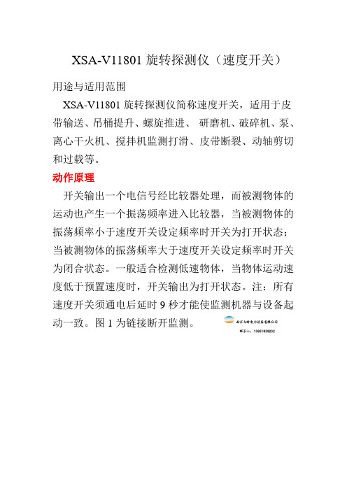
XSA-V11801旋转探测仪(速度开关)用途与适用范围
XSA-V11801旋转探测仪简称速度开关,适用于皮带输送、吊桶提升、螺旋推进、研磨机、破碎机、泵、离心干火机、搅拌机监测打滑、皮带断裂、动轴剪切和过载等。
动作原理
开关输出一个电信号经比较器处理,而被测物体的运动也产生一个振荡频率进入比较器,当被测物体的振荡频率小于速度开关设定频率时开关为打开状态;当被测物体的振荡频率大于速度开关设定频率时开关为闭合状态。
一般适合检测低速物体,当物体运动速度低于预置速度时,开关输出为打开状态。
注:所有速度开关须通电后延时9秒才能使监测机器与设备起
动一致。
图1为链接断开监测。
杰诺速度传感器说明书

3、齿形:渐开线或梯形直齿4、齿轮材料:导磁材料◆接线图:◆选型表齿轮传感器型号CL12-3005NACL12-3005PA输出方式NPNPNP外形直径12mm 额定感应距离(SN)5mm 检测频率1Hz┈10KHz检速范围1┈20000(转/分钟)(与合适齿轮配套)工作电压6...24VDC 防护等级IP67最大输出电流200mA 运行温度―25℃―+75℃保护措施有工作电压极性保护和输出短路保护注:如遇到传感器不感应时,可调近距离或手工测试下传感器最灵敏区域,安装时使齿轮经过此区域。
因传感器内部有永磁体,安装时应避免齿轮与传感器头之间因吸引而产生撞击。
◆概述:本传感器采用电磁感应原理来达到测速目的,具有输出信号大,不需要放大,抗干扰性能好,可在烟雾、油气、水汽等恶劣环境中使用等特点,可替代其他相关齿轮传感器,广泛用于国防化工,纺织机械领域。
◆产品特点:1.输出稳定方波、抗抖动能力强适用于各种场所的速度检测。
2.全密封设计,防水防油防尘;其优点是温度范围宽,热稳定性高,抗干扰能力强。
◆产品安装:1.安装时用传感器自带的螺母固定在安装孔上,固定装置建议采用非导磁材料(铜、不锈钢等),传感器应正对齿面安装,齿面和传感器前端面的间距不应大于额定检测距离。
2.检测距离与配套使用的检测齿轮的模数相关,模数越大可以有效检测的距离越长。
◆注意事项(1)传感器输出线中的金属屏蔽层应接大地另线。
(2)不允许在温度为250℃以上强磁场环境中使用及放置。
(3)安装及运输过程中应避免强烈撞击。
(4)在被测轴跳动较大时,应注意适当放大间隙,避免损坏。
◆检测齿轮1、模数:m≥12、齿轮厚度:≥4mm。
转角与角速度测量
一.摘要本报告立志于寻找除了光码盘传感器之外的其他类型传感器来进行转轴系统参数的测量。
包括测量转轴系统的角度,角速度。
本报告给出了,传感器的安装位置,传感器类型的选择,参数的选择,已经测量电路的绘制。
二.光码盘系统1. 光码盘简介光电式码盘是一种非接触性光电传感器,它具有测量准确度高、响应速度快、可靠性高和使用寿命长等优点。
我们应用光码盘测试原理,完成了直流电机测速装置设计(工作原理如图% 所示)。
其装置具有结构简单,测速准确度高的优点。
光码盘的工作原理就是用光码盘上透光与不透光,在码盘的另一侧形成光脉冲。
脉冲光照射在光电敏感元件上产生与光脉冲相对应的电脉冲。
典型的光码盘有TLP507A,TLP800等类型。
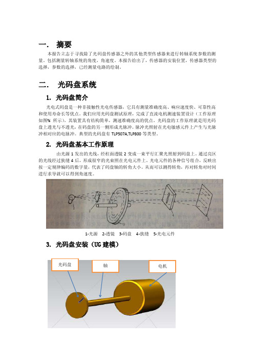
2. 光码盘基本工作原理由光源1发出的光线,经柱面透镜2变成一束平行汇聚光照射到码盘上。
通过亮区的光线经过狭缝4后,形成很窄的光束照在光电元件上。
光电元件的各种信号组合,反映出按一定规律编码的数字量,代表了码盘轴的转角大小。
从而可以测得转角,再对转角对时间进行求导就可以得到角速度。
1-光源2-透镜3-码盘4-狭缝5-光电元件3. 光码盘安装(UG建模)光码盘轴电机4.输出信号及其后续测量电路输出信号为数字信号,使用整形放大电路,为了确保转速测量准确度,使用单片机系统对脉冲信号处理。
5.实际可用的传感器类型及其参数6. 问题解答对于光码盘传感器来说,如采用二进制码编码,在设有8条码道的情况下,最小能够分辨测量多少度的转角?并需要多少个感光元件?答:采用二进制编码,在设有8条码道德情况下,最多可测量28=256次,因此,最小能够分辨角度360/256=1.41°因为需要设有8条码道,因此至少需要8个感光元件来支持设备的正常运行。
光元件。
三.电感式传感器系统1. 基本工作原理电感式传感器是利用电磁感应把被测的物理量如位移,压力,流量,振动等转换成线圈的自感系数和互感系数的变化,再由电路转换为电压或电流的变化量输出,实现非电量到电量的转换。
银河电气 VSA701-G150T02-I 电压传感器使用说明书_副本

VSA701-G150T02-I 电压传感器使用说明V1.0本手册为湖南银河电气有限公司产品电压传感器用户手册,本手册为用户提供安装调试、操作使用及日常维护的有关注意事项,在安装、使用前请仔细阅读。
本手册随产品一起提供,请妥善保管、以备查阅和维护使用。
声明我们非常认真的整理此手册,但我们对本手册的内容不保证完全正确。
因为我们的产品一直在持续的改良及更新,故我方保留随时修改本手册的内容而不另行通知的权利。
同时我们对不正确使用本手册所包含内容而导致的直接、间接、有意、无意的损坏及隐患概不负责。
安全操作知识◆产品使用前,请您务必仔细阅读用户手册。
◆需对产品进行搬动时,请您务必先断电并将与之相连的所有连接线缆等拔掉。
◆如果发现机壳、稳固件、电源线、连接线缆,或相连的设备有任何损坏,请您立即将装置与电源断开。
◆如果对设备的安全运行存在疑虑,应立即关闭设备和相应附件,并在最快时间内与本公司技术支持部门取得联系,沟通解决。
1. 产品概述VSA701-G150T02-I是一种能在原边、副边完全隔离条件下测量直流、交流、脉冲以及各种不规则波形的电压传感器,它主要用于要求准确度高的计量检定和计量校准领域,以及要求高灵敏度、高稳定性和高可靠性的电能质量分析、功率分析仪、医疗、航空航天、导弹、舰艇等领域。
2. 技术特点●极高的准确度●极好的线性度●极高的稳定性●极高的灵敏度●极高的分辨率●极低的温度漂移●极低的失调电压●抗干扰能力强●响应速度快●极低的噪声●极小的角差●宽频带●模拟量输出3. 应用场合●计量检定与校准●实验室电压测量●仪器仪表(如功率分析仪)●医疗设备(如核磁共振MRI)●电池组检测●电力控制●电源●舰船●新能源●轨道交通●航空航天●工业测量4. 电气性能项目 符号 测试条件数值单位最小标称最大原边额定电压 V PN -- -- 700 -- Vrms 测量范围 V PM 1分钟/小时 -- -- ±1000 Vp 工作电压 V c 全范围 -- ±15 -- VDC 电流消耗 I c I PM 范围内 -- ±80 -- mA变比 K N 输入:输出 1000:100 V/mA 额定输出 I SN 原边额定电压 --±100--mA测量电阻 R M全量程范围0 50 100 Ω5. 精度-动态参数项目 符号 测试条件 数值单位最小 标称 最大精度 X e额定输入,25±10℃--0.1-- %角差 ∆φ 50Hz -- 0.0315 -- ° 线性度 εL -- -- -- 100 ppm 零点失调电流 I o 25±10℃ -- -- ±5 uA 零点失调电流 I oT全工作温度范围内----±10 uA频带宽度(- 3 dB) F -- 0 -- 200 kHz6. 一般特性项目符号 测试条件数值单位最小标称最大工作温度范围 T A -- -10 -- +70 ℃ 存储温度范围T S-- -25 -- +85℃质量 m -- 350±30 g7. 安全特性项目符号 测试条件数值单位最小标称最大耐受 电压原、副边之间 副边与外壳之间V d DC -- 6 -- KV8. 外形尺寸及端口定义 8.1.外形尺寸 (单位:mm)图1 外形图外形图说明:外形尺寸、安装定位尺寸公差按照GB/T1804-2000 C 级标准执行。
杰诺XSAV11801速度传感器说明书

杰诺速度传感器
用途和适用范围
这些自含的转速监控传感器或称速度开关具有一体化的特征:在同一个外壳中,有脉冲检测、处理器和输出转换放大器,这些都是一个集成式转速检测装置所必须的。
这个装置为打滑检测、传送带损坏、传动轴切变与过载等问题提供了解决方案。
它应用于以下机器中:传送带、链式升降机、阿基米德式螺杆、研磨机、粉碎机、水泵、离心式甩干机、混合器等。
我公司生产的速度监测开关采用优质原件,先进设备生产,达到国产领先水平,我产品已被海螺水泥、徐工机械、白洋合水泥等大型工矿企业选择使用。
工作原理
这类接近传感器的输出信号是集成在传感器内的脉冲比较器处理的,由待监控部件产生的脉冲频率与传感器中的预置频率进行比较,当被测物体的频率小于速度开关设定频率时开关为打开状态;当被测物体的振动频率大于速度开关设定频率时开关为闭合状态。
我公司生产的转速监控传感器尤其适用于欠速的监控,当移动部件转速低于预设的临界值时,传感器的输出电路就关断。
注:通常传感器在通电后延迟9秒启动,以允许被监控对象有一个启动过程。
开关频率调整
首先用螺丝刀旋转拧开尾部直径8毫米的黑色旋钮,拿掉旋钮后,即可看到里面的电位计
调整传感器临界频率:使用电位计,大约15圈
增加传感器临界频率:顺时针旋转调节螺丝
减少传感器临界频率:逆时针旋转调节螺丝
电位计调整曲线:.
低速型高速型
开关最小安装距离(mm)与接线图
e≥20e≥120e≥30d≥30h≥0
接线图。
风速传感器说明书
一、产品概述 ..............................................................................................二、应用范围 ..............................................................................................三、技术参数 ..............................................................................................四、功能特点 ..............................................................................................五、结构尺寸图 ..........................................................................................六、固定方式 ..............................................................................................七、信号输出定义 ......................................................................................八、线色定义 ..............................................................................................九、脉冲型风速输出电路图 ......................................................................十、脉冲输出型计算 .................................................................................. 十一、RS485/232通讯协议 ....................................................................... 十二、风力等级划分表 .............................................................................. 十三、风速与输出信号对应表 ..................................................................一、产品概述该三杯式风速传感器是我公司自主研发、生产的一款风速测量仪器,本品由壳体、风杯和电路模块组成,内部集成光电转换机构、工业微电脑处理器、标准电流发生器、电流驱动器等。
汽车速度传感器用户指南(Bendix WS-24 SD-13-4860)说明书
1FIGURE 1 - WHEEL SPEED SENSORS AND CONNECTORSOPERATIONThe sensor's magnet and pole piece form a magnetic field.As an exciter tooth passes by the sensor, the magnetic field is altered, which generates AC voltage in the sensor coil.Each time an exciter tooth and its adjacent space move past the tip of the sensor, an AC voltage "cycle" is generated.DESCRIPTIONThe WS-24™ wheel speed sensor is an electromagnetic device used to obtain vehicle speed information for an antilock controller. When the wheel rotates, the sensor and an exciter ring (sometimes called a “rotor” or “tone” wheel)generate a simple AC signal. This signal is sent to the controller, which analyzes the data and commands the antilock system accordingly.Specifically, the speed sensor consists of a coil, pole piece,and magnet. The exciter is a steel ring or gear-like device that has regularly spaced high and low spots called "teeth."The sensor is mounted in a fixed position, while the exciter is installed on a rotating member so that its "teeth" move, in close proximity, past the tip of the sensor.The WS-24™ sensor is available in both straight and right angle versions, to accommodate axle/wheel spacelimitations. (See Figure 1.)PREVIOUS MODEL WHEEL SPEED SENSORSThe WS-24™ sensor fit and function is compatible with all previous Bendix models.EXCITER RINGMOUNTING BLOCK WHEEL SPEED SENSORFIGURE 2 - WHEEL END ABS COMPONENTSSTRAIGHT WS-24™SENSOR90° WS-24™SENSORCONNECTORSPACKARD GT 150 SERIESPACKARD METRIPACK 150.2 SERIESDEUTSCH DTM06 SERIESPACKARD METRIPACK 280SERIES (FEMALE)PACKARD METRIPACK 280SERIES (MALE)DEUTSCH DT04SERIESSTANDARD ROUND TWOPIN2The number of AC cycles per revolution of the vehicle's wheel depends on the number of teeth in the exciter, which is programmed into the antilock controller. Using the programmed data, the controller can calculate "vehicle speed" by analyzing the frequency of AC cycles sent by the speed sensor. (The frequency of AC cycles is directly proportional to wheel speed.) See Figure 4.AC voltage is also proportional to speed, but voltage is not used to determine speed. It is only an indication of AC signal strength. The amount of AC voltage generated by a specific speed sensor depends on the distance, or "gap"between the tip of the sensor and the surface of the exciter.Voltage increases as the sensor gap decreases.Typically, the WS-24™ sensor is installed in mounting blocks that are welded to the axle housing. (See Figure 2.)WS-24™ wheel speed sensors are protected by a stainless steel sheath. They are designed to be used with beryllium-copper clamping sleeves (sometimes referred to as a “retainer bushing”, “friction sleeve” or “clip”) (See Figure 3).The clamping sleeve provides a friction fit between the mounting block bore and the WS-24™ sensor.Please note that WS-24™ wheel speed sensors must use clamping sleeve p/n 5012878 instead of p/n 5006849 (used for previous wheel speed sensors). Always use correct clamping sleeves to avoid problems associated with reduced retention force, such as sensor movement and resulting ABS trouble codes.The friction fit allows the WS-24™ sensor to "slide" back and forth under force but to retain its position when the force is removed.When the WS-24™ sensor is inserted all the way into the mounting block and the wheel is installed on the axle, the hub exciter contacts the sensor, which pushes the sensor back. Also, normal bearing play will "bump" the sensor away from the exciter. The combination of these two actions will establish a running clearance or air gap between the sensor and exciter.FIGURE 4 - SPEED SENSOR VOLTAGE CYCLE OUTPUTPEAK TO PEAKPEAK TO PEAKHIGH SPEEDLOW SPEEDTECHNICAL INFORMATIONElectrical connector 2 Pin.Sensor resistance 1500-2500 ohmsOutput voltageAt a minimum of 100Hz (approximately 7 mph) the sensor output across the leads should be 0.400 VAC.Sensor gap 0 to 0.015 inch.Sensor body Outer diameter is 0.627 inch.Normal resistance 1500-2000 Ohms.range across pins (Note: Previous model WS-20™at room temperaturesensor was rated at 2000-2500Ohms.)FIGURE 5 - TYPICAL ANTILOCK SYSTEMFIGURE 3 - CLAMPING SLEEVESP/N 5006849P/N 5012878CORRECT CLAMPING SLEEVES PREVIOUS CLAMPING SLEEVES HAVEPREVENTIVE MAINTENANCE1.Every 3 months; 25,000 miles; 900 operating hours; orduring the vehicle chassis lubrication interval, make the visual inspections noted in "SERVICE CHECKS" below.2.Every 12 months; 100,000 miles; or 3600 operatinghours, perform the OPERATIONAL TEST in this manual. SERVICE CHECKSCheck all wiring and connectors. Make sure connections are free from visible damage.Examine the sensor. Make sure the sensor, mounting bracket, and foundation brake components are not damaged. Repair/replace as necessary.WARNING! PLEASE READ AND FOLLOW THESE INSTRUCTIONS TO AVOID PERSONAL INJURY OR DEATH:When working on or around a vehicle, the following general precautions should be observed at all times.1.Park the vehicle on a level surface, apply the parkingbrakes, and always block the wheels. Always wear safety glasses.2.Stop the engine and remove ignition key whenworking under or around the vehicle. When working in the engine compartment, the engine should be shut off and the ignition key should be removed.Where circumstances require that the engine be in operation, EXTREME CAUTION should be used to prevent personal injury resulting from contact withmoving, rotating, leaking, heated or electrically charged components.3.Do not attempt to install, remove, disassemble orassemble a component until you have read and thoroughly understand the recommended procedures. Use only the proper tools and observe all precautions pertaining to use of those tools. 4.If the work is being performed on the vehicle’s airbrake system, or any auxiliary pressurized air systems, make certain to drain the air pressure from all reservoirs before beginning ANY work on the vehicle. If the vehicle is equipped with an AD-IS™ air dryer system or a dryer reservoir module, be sure to drain the purge reservoir.5.Following the vehicle manufacturer’s recommendedprocedures, deactivate the electrical system in a manner that safely removes all electrical power from the vehicle.6.Never exceed manufacturer’s recommendedpressures.7.Never connect or disconnect a hose or linecontaining pressure; it may whip. Never remove a component or plug unless you are certain all system pressure has been depleted.e only genuine Bendix® replacement parts,components and kits. Replacement hardware, tubing, hose, fittings, etc. must be of equivalent size, type and strength as original equipment and be designed specifically for such applications and systems.ponents with stripped threads or damagedparts should be replaced rather than repaired. Do not attempt repairs requiring machining or welding3unless specifically stated and approved by the vehicle and component manufacturer.10.Prior to returning the vehicle to service, make certainall components and systems are restored to their proper operating condition.11.For vehicles with Antilock Traction Control (ATC),the ATC function must be disabled (ATC indicator lamp should be ON) prior to performing any vehicle maintenance where one or more wheels on a drive axle are lifted off the ground and moving. REMOVAL1.Unplug the cable assembly connector from its lead. Liftthe lock tab and pull on the connector until it disengages.2.Gently pry the sensor and clamping sleeve from themounting block.INSPECTIONLook for any visible damage to the sensor, cable assembly, connector, mounting block, and foundation brake. Repair or replace any damaged components. Make sure the block is securely attached to the axle housing.SENSOR INSTALLATION1.For increased corrosion protection we recommend thata high-temperature rated silicon- or lithium-based greasebe applied to the interior of the mounting block, the sensor, and to a new clamping sleeve.2.Install the new clamping sleeve fully into the block, withthe retaining tabs toward the inside of the vehicle.3.Gently push (DO NOT STRIKE) the sensor into themounting block hole until it bottoms out on the face of the tone ring. Secure the cable lead wire to the knuckle/ axle housing 3-6 inches from the sensor.4.Apply a moderate amount of dielectric non-conductivegrease to both the sensor connector and harness connector.5.Engage the connectors, and push together until the locktab snaps into place.NOTE:It is important for the wheel bearings to be adjusted per the manufacturer's recommendations.Excessive wheel end play can result in antilockfunction shutdown in cases where the sensor ispushed too far away from the tone ring. ELECTRICAL TESTING1.Before testing the speed sensor, its location on thevehicle should be confirmed using the Troubleshooting or Start Up procedure for the specific antilock controllerin use. (See the Service Data Sheet for the antilock controller for this procedure.)2.Proceed to the sensor in question and inspect its wiringconnector. Disconnect the connector and test the resistance between the pins ON THE SENSOR.Normal resistance range across pins at room temperature should be 1500-2000 Ohms. (Note: Previous model WS-20™ sensor was rated at 2000-2500 Ohms.)Individually test the resistance of each pin to vehicle ground and note there is NO CONTINUITY.If the resistance readings are as shown, the wire harness leading to the modulator may require repair or replacement. Before attempting repair or replacement of the wire harness, refer to the test procedures specified for the antilock controller in use for possible further testing that may be required to substantiate the wire harness problem. If the resistance values are NOT AS STATED, replace the sensor. Resistance could be as low as 1100 Ohms or as high as 3300 Ohms if wheel end has recently been exposed to extreme temperature.OPERATIONAL TESTINGTo test sensor operation, one of two tests can be done. TEST 1Drive the vehicle in a safe area to a minimum speed of 15 mph. Be sure to apply the vehicle brakes several times. Then stop the vehicle and check the LED display on the Bendix controller. If the dash light is out and the sensor LED(s) are not illuminated, the sensor is installed properly. TEST 2Disconnect the connector from the sensor's socket or from the attached lead. Raise the vehicle wheel so it rotates easily. Connect a volt-Ohm meter (set to read Volts AC) to the pins on the sensor or lead and spin the wheel. If the wheel is spun at 1/2 revolution per second the reading should be greater than 0.250 VAC.If the sensor fails to operate as described, check the wiring from the controller to the sensor. Make sure all connectors are properly and tightly installed. Check for frayed or damaged wires and check and/or reset the sensor air gap (distance from sensor tip to exciter ring) as described in this manual. For additional troubleshooting information, see the troubleshooting procedure for the specific antilock system in use.BW2364 © 2004 Bendix Commercial Vehicle Systems LLC. All rights reserved. 9/2004. Printed in U.S.A.4。
巴克尔(Parker)速度传感器Series F10 F11 F12和V12 V14 T12 说明书
Bulletin MSG30-8303-INSTSpeed Sensor Series F10/F11/F12 and V12/V14/T12Valid for sensor 3722481Effective: March, 2023Supersedes: November, 2022Visit our homepage for additional support/pmdeGeneral InformationThe sensor consists of a ferrostat differ-ential (Dual Channel) speed sensor and a seal nut. The sensor installs in a threaded hole in the housing. The sensor output is a2 phase shifted square wave signal withina frequency rang of 0 Hz to 15 kHz. The sensor detects both speed and direction of rotation. The sensor withstands high as well as low temperatures and is highly moisture protected (IP68).Technical DataPower supply 10V to 30V protectedagainst reverse polarity. Current Max 20 mA. consumption (without load)Signal output • 2 phase shifted signals square waves• Open collector outputswith 10 Kohm pull-up,Imax = -20 mA.Frequency Min 0 Hz max 15 kHz Insulation Housing and electronicsgalvanically separated(500V/50Hz/1 min)Operating -40 to +125 °C temperature [-40 to +255 °F]Protection class IP68 (DIN 40050)SensorIP67 (DIN 40050)ConnectorSensor head Max 25 bar pressure [360 psi]Weight 0.15 kg(incl. cable) [0.33 lb]Sensing distance 0.1 to 2.0 mm;1.0 recom.[0.004 to 0.08 in;0.04 recom.]Transistor NPNAmplifier variant Variant; .02 SHWOutput 1: SpeedOutput 2: SpeedOutput type: Open Col. CABLEMaterialPUR castingLength 260 mmNo. of wires 4-Wire area 4 x 0.34 mm²Connector M12X1, Male,Straight 4 PinBending radiusMin 50 mm [1 in]Installation Procedure • I nstall the sensor in the threaded hole (M12x1) of the F10-30-125/V12/V14/T12bearing housing; turn the sensor until its head just touches the ring gear teeth (F10/F12) or the shaft head (F12-250/V12/V14/T12); refer to the installation drawing above.• O n *F10-5-19/F11 the pistons positionsmust be known before mounting the sen-sor. Install the sensor in the threaded hole(M12x1) of the F11 barrel housing; turnthe sensor until its head just touches thepiston.• W hen mounting the sensor in the thread-ed hole be sure that you also rotate the cable so the cable not get twisted.• B ack off the sensor one turn (counter clockwise).• I f required, back it off further until the sensor guiding hole centerline is either as shown in Fig. 1 & 2 or 180° opposite.• T ighten the seal nut; max 12 Nm (100 lb in). Be sure that the position of the guid-ing mark is correct.• I f you only use one signal, we recommend you to use S2 cable.ConnectionSensor wires are susceptible to radiated noise. Therefore, the following shoud be noted:- The sensor wires must be installed as far away as possible from electricalmachines and must not run in parallel with power cables in the vicinity.The maximum cable length that can be uti-lized is dependent on sensor voltage, how the cable is installed, and cable capacitance and inductance. It is, however, always ad-vantageous to keep the distance as short as possible. The sensor cable supplied can be lengthened via a terminal box located in an IP20 protected connection area (per DIN 40050).Pulse diagram:Connections:M12X1, Male, Straight 4 Pin Pin 1 RED - VDCInstallation InformationAs the sensor has a built-in differential Hall effect device, the sensor housing must bealigned according to the drawing (Fig. 1& 2) of the Speed Sensor Installation picture. If it is not, the sensor may not function properly and noise immunity decreases. The sensor is non-sensitive to oil and the stainless steel housing withstands hazardous environment conditions.S1S2directions of rotation directions of rotation 13Speed sensor intallation, F10-30-125, F12, V12,V14Fig. 1Bearing housingFixed and Variable MotorsSeries F10/F11/F12 and V12/V14/T12Bulletin MSG30-8303-INSTMarketing informationOffer of SalePlease contact your Parker representation for a detailed ”Offer of Sale”.Position notification regarding Machinery Directive 2006/42/EC:Products made by the Pump & Motor Division Europe (PMDE) of Parker Hannifin are excluded from the scope of the machinery directive following the “Cetop” Position Paper on the implementation of the Machinery Directive 2006/42/EC in the Fluid Power Industry.All PMDE products are designed and manufactured considering the basic as well as the proven safety principles according to: • ISO 13849-1:2015 • SS-EN ISO 4413:2010so that the machines in which the products are incorporated meet the essential health and safety requirements.Confirmations for components to be proven component, e. g. for validation of hydraulic systems, can only be provided after an analysis of the specific application, as the fact to be a proven component mainly depends on the specific application.Christian Jäger General MangerPump & Motor Division EuropeParker Hannifin Manufacturing Sweden AB Pump & Motor Division Europe Flygmotorvägen 2 MSG30-8303-INST 461 82 Trollhättan Art. No 3722353-01SwedenTel. +46 (0)520 40 45 00 © Copyright /pmdeAll rights reserved。
坎诺达尔轮速传感器部件说明书
1 of 4 134946 Rev 1 - Pubblicato il: 05/15/19• Il sensore ruota utilizza un sistema di adattatori di montaggio in due parti per il montaggio su diversi tipi di mozzo/ruota.Vedere pagina 3 Compatibilità dell’adattatore di montaggio. Isegni di identificazione dell’adattatore sono impressi nel supporto dell’adattatore in gomma e nel morsetto dell’adattatore.• Un montaggio diverso del sensore da quello specificato può causare danni al sensore stesso e/o alla ruota o provocare ildistaccamento del sensore ruota.• Il sensore deve essere montato verticalmente rispetto all’interno dei raggi sul lato non di trasmissione della ruota anteriore e deveessere a contatto con due raggi. Tuttavia, quando si pedala alchiuso, il sensore può essere spostato sul lato non di trasmissione della ruota posteriore utilizzando l’adattatore 0A. Ciò può compor-tare una leggera inclinazione del sensore, che non ne pregiudica il funzionamento. Il montaggio del sensore in qualsiasi altro orien-tamento comporta una lettura meno precisa della velocità e della distanza.• Posizionare il sensore ruota e fissarlo il più vicino possibile all’asse del mozzo con la superficie inferiore curva che corrisponda allacurvatura del mozzo.Vedere CORRETTO, INCORRETTO.Strumenti necessari:Occhiali di sicurezza, guanti da lavoro, chiave esagonale: Chiave esa-gonale da 2 mm2431Installazione1. Inserire il supporto dell’adattatore nel corpo del sensore ruota.2. Posizionare il morsetto del raggio sulla ruota come specificato in Compatibilità dell’adattatore di montaggio. Pagina3.3. Posizionare il sensore ruota all’interno dei raggi e allineare il foro del bullone del morsetto di montaggio con il foro del sensore ruota. Premere e tenere insieme le due parti.4.Utilizzando una chiave esagonale da 2 mm, serrare il bullone adattatore a 0,5 Nm, tenendoCompatibilità dell’adattatore di montaggio2ASolo mozzi HollowGram KNØT2BRaggiatura in seconda con il raggio d’uscita sul lato INTERNO della flangia.NOTA: Se il morsetto per raggio non si adatta agli angoli dei raggi, utilizzare l’adattatore dimontaggio 0A.4 of 4Si prega di fare riferimento . alla propria regione per letraduzioni linguistiche disponibili.I termini “componenti” si applicano a questo accessorio. Per ulteriori infor-mazioni, visitare l’area di supporto all’indirizzo .Contattare CannondaleAndare su . per informazioni di contatto perla propria regione.Sostituzione della batteriaVedere anche “Garmin Informazioni importanti sulla sicurezza e sul prodotto”.Per controllare il livello della batteria, far fare due giri alla ruota. Se il LED (a) sul corpo del sensore ruota lampeggia in rosso, il livello della batteria è basso.bcdb“+”ag1. Rimuovere il sensore ruota dalla ruota utilizzando una chiave esagonale da 2 mm.2.Utilizzare una moneta nell’alloggiamento del coperchio (b) e ruotare il coperchio in senso antiorario fino a quando il trattino del coperchio (c) si allinea con il simbolo di sblocco (d) e viene allentato.Se necessario, utilizzare con cautela un piccolo cacciavite piatto sottile posto sotto il lembo del coperchio per sollevarlo. Usare solo una leggera pressione per evitare di danneggiare il coperchio, l’o-ring di guarnizione (e) o il coperchio. Non ruotare il cacciavite.3. Rimuovere la batteria dall’alloggiamento. Attendere 30 secondi.4.Inserire la nuova batteria (g) con il simbolo positivo “+” sulla batteria rivolto verso l’alto. Prendere nota del contrassegno “-” (h) nel coperchio, il contrassegno della batteria deve essere rivolto verso di esso. Individuare delle piccole linguette (f); inclinare leggermente la batteria sotto queste linguette prima di premerla.5.Per reinstallare nell’alloggiamento dell’unità, allineare il trattino del coper-chio (c) con il simbolo di sblocco (d) e inserire il coperchio con la batteria nuova.6.Utilizzare la moneta con una leggera pressione verso il basso e ruotare lo sportello della batteria in senso orario fino a quando il trattino del coperchio è allineato con il simbolo “CHIUSO”. Controllare lo sportello della batteria per assicurarsi che sia a filo con l’alloggiamento e non inclinato, mostrando o stringendo la guarnizione o-ring arancione. Allentare il coperchio e riprovare.NOTA: Il LED (a) lampeggia in rosso e verde per alcuni secondi dopo la sostituzione della batteria. Quando il LED lampeggia in verde e poi smette di lampeggiare, il dispositivo è attivo e pronto per l’invio dei dati.La prima volta che si collega un sensore wireless al dispositivo utilizzando la tecno-logia ANT+® o Bluetooth® , è necessario associare il dispositivo e il sensore. Dopo l’accoppiamento, il dispositivo si collega automaticamente al sensore quando si ini -zia un’attività e il sensore è attivo ed entro il raggio d’azione.NOTA: Le istruzioni di accoppiamento differiscono per ogni dispositivo compatibile con ANT+ o Bluetooth. Vedere il manuale d’uso.• Portare il dispositivo compatibile con ANT+ o Bluetooth entro 3 m dal sen sore.• Stare a 10 m di distanza da altri sensori wireless durante l’accoppiamento.Dopo il primo accoppiamento, il dispositivo compatibile con ANT+ o Bluetooth riconosce automaticamente il sensore wireless ogni volta che viene attivato.Il Sensore ruota Cannondale deve essere accoppiato direttamente tramite l’appli -cazione Cannondale e non dalle impostazioni Bluetooth dello smartphone.1. Dall’App store sul proprio smartphone, installare e aprire l’App Cannondale.2. Portare il proprio smartphone a meno di 3 m dal sensore ruota.NOTA: Rimanere a 10 m di distanza da altri sensori wireless durante l’accoppia -mento.3. Mentre si è sulla schermata Pair a Sensor nell’Aapp Cannondale, far fare alla ruota anteriore almeno 2 giri per riattivare il sensore ruota. Il sensore ruota è atti-vo quando il LED nel vano batteria lampeggia in verde.4. Continuare a seguire le istruzioni nell’App Cannondale.NOTA: Se si abbina un sensore ruota supplementare all’App Cannondale:aggiungere una nuova bici al proprio Cannondale App Garage utilizzando un sen-sore ruota, facendo clic su “+Add Bike” dalla schermata Garage.oppureaggiungere un sensore ruota a una bicicletta esistente nel proprio Cannondale App Garage facendo clic su “+Add Sensor” dalla schermata Bike Details. Questo può essere utile se si hanno due set di ruote per una bicicletta .CHIUSOse allineato in questo modo.。
- 1、下载文档前请自行甄别文档内容的完整性,平台不提供额外的编辑、内容补充、找答案等附加服务。
- 2、"仅部分预览"的文档,不可在线预览部分如存在完整性等问题,可反馈申请退款(可完整预览的文档不适用该条件!)。
- 3、如文档侵犯您的权益,请联系客服反馈,我们会尽快为您处理(人工客服工作时间:9:00-18:30)。
杰诺速度传感器
用途和适用范围
这些自含的转速监控传感器或称速度开关具有一体化的特征:在同一个外壳中,有脉冲检测、处理器和输出转换放大器,这些都是一个集成式转速检测装置所必须的。
这个装置为打滑检测、传送带损坏、传动轴切变与过载等问题提供了解决方案。
它应用于以下机器中:传送带、链式升降机、阿基米德式螺杆、研磨机、粉碎机、水泵、离心式甩干机、混合器等。
我公司生产的速度监测开关采用优质原件,先进设备生产,达到国产领先水平,我产品已被海螺水泥、徐工机械、白洋合水泥等大型工矿企业选择使用。
工作原理
这类接近传感器的输出信号是集成在传感器内的脉冲比较器处理的,由待监控部件产生的脉冲频率与传感器中的预置频率进行比较,当被测物体的频率小于速度开关设定频率时开关为打开状态;当被测物体的振动频率大于速度开关设定频率时开关为闭合状态。
我公司生产的转速监控传感器尤其适用于欠速的监控,当移动部件转速低于预设的临界值时,传感器的输出电路就关断。
注:通常传感器在通电后延迟9秒启动,以允许被监控对象有一个启动过程。
开关频率调整
首先用螺丝刀旋转拧开尾部直径8毫米的黑色旋钮,拿掉旋钮后,即可看到里面的电位计
调整传感器临界频率:使用电位计,大约15圈
增加传感器临界频率:顺时针旋转调节螺丝
减少传感器临界频率:逆时针旋转调节螺丝
电位计调整曲线:.
低速型高速型
开关最小安装距离(mm)与接线图
e≥20e≥120e≥30d≥30h≥0
接线图。