中英文文献翻译-具有车架结构车辆怠速震动的分析
怠速抖动故障诊断的总结作文
怠速抖动故障诊断的总结作文英文回答:Idle shaking is a common problem in vehicles and can be caused by various factors. As a mechanic, diagnosing and fixing this issue requires a systematic approach. Here is a summary of the steps I would take to diagnose an idle shaking problem.Firstly, I would start by checking the engine'scondition and ensuring that all basic maintenance taskshave been performed. This includes checking the spark plugs, air filter, and fuel filter. Sometimes, a simple maintenance task can resolve the idle shaking issue.If the basic maintenance tasks do not solve the problem, I would move on to checking for vacuum leaks. Vacuum leaks can disrupt the air-fuel mixture and cause the engine to shake at idle. I would use a smoke machine or a can of carburetor cleaner to detect any leaks around the intakemanifold, vacuum hoses, or throttle body.If no vacuum leaks are found, the next step is toinspect the ignition system. Faulty ignition componentssuch as ignition coils or spark plug wires can causemisfires and idle shaking. I would use a diagnostic tool to check for any trouble codes related to the ignition system and perform a visual inspection of the ignition components.In some cases, a dirty or malfunctioning idle aircontrol valve (IACV) can also lead to idle shaking. The IACV controls the amount of air entering the engine at idle. If it becomes clogged or fails, it can cause the engine to shake. I would clean or replace the IACV if necessary.Another potential cause of idle shaking is a malfunctioning throttle body. A dirty or stuck throttlebody can disrupt the airflow and cause the engine to shake. Cleaning or replacing the throttle body can often resolve this issue.Lastly, if all the above steps do not solve the problem,I would check the engine mounts. Worn or damaged engine mounts can cause excessive engine movement, leading to idle shaking. I would visually inspect the engine mounts and replace them if necessary.In conclusion, diagnosing and fixing idle shaking requires a thorough inspection of the engine's condition, checking for vacuum leaks, inspecting the ignition system, cleaning or replacing the idle air control valve and throttle body, and inspecting the engine mounts. By following these steps, I can effectively diagnose and resolve idle shaking issues in vehicles.中文回答:怠速抖动是车辆常见的问题,可能由多种因素引起。
车架有限元分析外文文献翻译

南京林业大学本科毕业设计(论文)外文资料翻译翻译资料名称(外文)Stress analysis of heavy duty truck chassis as apreliminary data for its fatigue life predictionusing FEM翻译资料名称(中文)利用重型载货汽车的有限元应力分析的初步数据预测其疲劳寿命院(系):汽车与交通工程学院专业:机械制造及其自动化(汽车设计方向)姓名:学号:指导教师:完成日期: 2012/5/31利用重型载货汽车的有限元应力分析的初步数据预测其疲劳寿命Roslan Abd Rahman, Mohd Nasir Tamin, Ojo Kurdi马来西亚工程大学机械工程系81310 UTM, Skudai,Johor Bahru摘要本文对一重型货车底盘做了应力分析。
应力分析能够确定零件的最大受力点,是分析零部件疲劳研究和寿命预测的重要手段。
前人已有用商用有限元软件ABAQUS软件对底盘模型进行分析的。
本次研究的底盘长12.35米,宽2.45米,材料是ASTM低合金钢710(3级),屈服极限552MPa,抗拉强度620MPa。
分析结果显示,最大应力点出现在底盘与螺栓连接的空缺处,最大应力为386.9MPa,底盘的疲劳破坏将会从最大应力点开始向车架各部位蔓延。
关键字:应力分析,疲劳寿命预测,货车底盘1.0简介在马来西亚,很多货车的车架寿命都有20多年,20多年架就会有使用安全的问题。
因此,为了确保底盘在工作期间的安全性能,就有必要对底盘作疲劳研究和寿命预测。
利用有限元法作应力分析能够确定受最大应力的关键点,这个关键点是导致底盘疲劳损伤的因素之一。
应力的大小能够预测底盘的寿命,所以可以根据应力分析的结果精确地预测底盘的寿命,应力分析越精确,底盘寿命预测的越合理。
本文是用商用有限元软件ABAQUS 软件完成底盘应力分析的。
汽车工业(汽车总成及各部件)在马来西亚的工业中占据非常重要的地位。
中英文文献翻译—汽车车架的结构
中英文文献翻译—汽车车架的结构The frame is the basic XXX components。
If the frame is too flexible。
it XXX and control。
On the other hand。
if the frame is too rigid。
it can cause unnecessary ns that can be felt by the driver and passengers。
Thus。
the design of the car's frame and XXX the car's noise level。
n strength。
XXX.Car manufacturers use several different frame structures in their n。
One of the most commonly used structures is the shell and girders of n structure。
which has been used since the 1970s。
This structure provides a balance een XXX。
allowing for XXX driving.However。
it is important to note that the frame structure isjust one aspect of a car's overall design。
Other factors。
such asthe engine。
n。
and aerodynamics。
XXX。
car manufacturers must carefully consider all aspects of a car's design to create ahigh-quality and XXX.At present。
外文翻译---悬架系统的基本元件

附录Ⅰ外文资料及翻译As we review suspension system components and how they work together, remember that a vehicle in motion is more than wheels turning. As the tire revolves, the suspension system is in a dynamic state of balance, continuously compensating and adjusting for changing driving conditions. Today's suspension system is automotive engineering at its best.The components of the suspension system perform six basic functions:1.Maintain correct vehicle ride height2.Reduce the effect of shock forces3.Maintain correct wheel alignment4.Support vehicle weight5.Keep the tires in contact with the road6.Control the vehicle’s direction of travelHowever, in order for this to happen, all the suspension components, both front and rear, must be in good working condition.MAIN COMPONENTS OF A MODERN SUSPENSION SYSTEMAt this point, it's important to understand that the main components of a moving vehicle suspension system are the Struts, Shock Absorbers, Springs and Tires. We will first turn our attention to the design and function of springs. In the following section we will thoroughly examine the function and design of shock absorbers and strut assemblies.The springs support the weight of the vehicle, maintain ride height, and absorb road shock..Springs are the flexible links that allow the frame and the body to ride relatively undisturbed while the tires and suspension follow the bumps in the road.Springs are the compressible link between the frame and the body. When an additional load is placed on the springs or the vehicle meets a bump in the road, the springs will absorb the load by compressing. The springs are a very important component of the suspension system that provides ride comfort. Shocks and strutshelp control how fast the springs and suspension are allowed to move, which is important in keeping tires in firm contact with the road.During the study of springs, the term bounce refers to the vertical (up and down) movement of the suspension system. The upward suspension travel that compresses the spring and shock absorber is called the jounce, or compression. The downward travel of the tire and wheel that extends the spring and shock absorber is called rebound, or extension.When the spring is deflected, it stores energy. Without shocks and struts the spring will extend and release this energy at an uncontrolled rate. The spring's inertia causes it to bounce and overextend itself. Then it re-compresses, but will again travel too far. The spring continues to bounce at its natural frequency until all of the energy originally put into the spring is used.If the struts or shock absorbers are worn and the vehicle meets a bump in the road, the vehicle will bounce at the frequency of the suspension until the energy of the bump is used up. This may allow the tires to lose contact with the road.Struts and shock absorbers that are in good condition will allow the suspension to oscillate through one or two diminishing cycles, limiting or damping excessive movement, and maintaining vertical loads placed upon the tires. This helps keep the tires in contact with the road.By controlling spring and suspension movement, components such as tie rods will operate within their design range and, while the vehicle is in motion, dynamic wheel alignment will be maintained.SPRING DESIGNSBefore discussing spring design, it is important to understand sprung and unsprung weight. Sprung weight is the weight supported by the springs. For example, the vehicle's body, transmission, frame, and motor would be sprung weight. Unsprung weight is the weight that is not carried by springs, such as the tires, wheels, and brake assemblies.The springs allow the frame and vehicle to ride undisturbed while the suspension and tires follow the road surface. Reducing unsprung weight will provide less road shock. A high sprung weight along with a low unsprung weight provides improved ride and also improved tire traction.There are four major spring designs in use today: coil, leaf, torsion bar, and air.Coil SpringsThe most commonly used spring is the coil spring. The coil spring is a length of round spring steel rod that is wound into a coil. Unlike leaf springs, conventional coil springs do not develop inter-leaf friction. Therefore, they provide a smoother ride.The diameter and length of the wire determine the strength of a spring. Increasing the wire diameter will produce a stronger spring, while increasing its length will make it more flexible.Spring rate, sometimes referred to as deflection rate, is used to measure spring strength. It is the amount of weight that is required to compress the spring 1 inch. For example: If it takes 100 lbs. to compress a spring 1inch, it would take to 200 lbs. to compress the spring 2 inches.Some coil springs are made with a variable rate. This variable rate is accomplished by either constructing this spring from materials having different thickness or by winding the spring so the coil will progressively compress at a higher rate. Variable rate springs provide a lower spring rate under unloaded conditions offering a smoother ride, and a higher spring rate under loaded conditions, resulting in more support and control.Coil springs require no adjustment and for the most part are trouble-free. The most common failure is spring sag. Springs that have sagged below vehicle design height will change the alignment geometry. This can create tire wear, handling problems, and wear other suspension components. During suspension service it is very important that vehicle ride height be measured. Ride height measurements not within manufacturer’s specifications require replacement of springs.Leaf SpringsLeaf springs are designed two ways: multi-leaf and mono-leaf. The multi-leaf spring is made of several steel plates of different lengths stacked together. During normal operation, the spring compresses to absorb road shock. The leaf springs bend and slide on each other allowing suspension movement.An example of a mono-leaf spring is the tapered leaf spring. The leaf is thick in the middle and tapers toward the two ends. Many of these leaf springs are made of a composite material, while others are made of steel.In most cases leaf springs are used in pairs mounted longitudinally (front to back). However, there are an increasing number of vehicle manufacturers using a single transverse (side to side) mounted leaf spring.Torsion BarAnother type of spring is the torsion bar. The torsion bar is a straight or L shaped bar of spring steel. Most torsion bars are longitudinal, mounted solidly to the frame at one end and connected to a moving part of the suspension at the other. Torsion bars may also be transverse mounted. During suspension movement, the torsion bar will twist, providing spring action.Air SpringsThe air spring is another type of spring that is becoming more popular on passenger cars, light trucks, and heavy trucks. The air spring is a rubber cylinder filled with compressed air. A piston attached to the lower control arm moves up and down with the lower control arm. This causes the compressed air to provide spring action. If the vehicle load changes, a valve at the top of the airbag opens to add or release air from the air spring. An onboard compressor supplies air.Tires as SpringsAn often-overlooked spring is the tire. Tires are air springs that support the total weight of the vehicle. The air spring action of the tire is very important to the ride quality and safe handling of the vehicle. As a matter of fact, tires may be viewed as the number-one ride control component. Tire size, construction, compound and inflation are very important to the ride quality of the vehicle.STRUT MOUNTDESIGNStrut mounts are vehicle specific, and there are numerous designs in use today on both front and rear suspension systems. The three most common designs are inner plate, center sleeve, and spacer bushing.The Inner Plate Design used by General Motors and some Ford applications feature an inner plate encased in molded rubber surrounded by upper and lower surface plates. The inner plate is designed so the strut piston rod cannot push through the upper or lower surface plate if the rubber core fails. This design generally does not require washers. Due to the fact that the upper and lower service plates mostly cover the rubber portion of the mount, it is difficult to see if the inner rubber bushing has failed. However, these components wear over time and with a thorough inspection a proper recommendation can be made. The bearing is located on the bottom of the strut mount and is not serviceable. Defective bearing will require replacement of the entire strut mount.The Center Sleeve Design used by Chrysler features a center sleeve that is molded to the rubber bushing. This design provides increased side to side stability.The strut stem extends through the center sleeve. Upper and lower retainer washers prevent the strut rod from pushing through the strut mount. The bearing is a separate component from the strut mount. If inspection reveals cracks or tears in the rubber bushing, replacement is required. If the bearing is found to be defective it can be replaced separately.The Spacer Bushing Design used by V olkswagen, Toyota, Mazda, Mitsubishi, and early Chrysler vehicles feature center positioning of the bearing and a separate inner bushing instead of a molded inner sleeve. The operation is similar to the style we just discussed except the bearing is pressed in the strut mount. The bearings, washer, and the upper plate retain the strut rod. If the rubber bushing is cracked, torn, or the bearing is binding or seized, the strut mount requires replacement.ANTI-SWAY BARSAnother important component of a suspension system is the anti-sway bar. This device is used along with shock absorbers to provide additional stability. The anti-sway bar is simply a metal rod connected to both of the lower control arms. When the suspension at one wheel moves up and down the anti-sway bar transfers the movement to the other wheel. In this way the sway bar creates a more level ride and reduces vehicle sway or lean during cornering.Depending of the anti-sway bar thickness and design, it can provide as much as 15% reduction in the amount of vehicle roll or sway during cornering.BUSHINGSBushings are used in many locations on the vehicle suspension system. Most bushings are made with natural rubber. However, in some cases, urethane compounds may be used. Bushings made of natural rubber offer high tensile (tear) strength and excellent stability at low temperatures. Natural rubber is an elastomeric material. Elastomeric refers to the natural elastic nature of rubber to allow movement of the bushing in a twisting plane. Movement is controlled by the design of the rubber element. Natural rubber requires no lubrication, isolates minor vibration, reduces transmitted road shock, operates noise free, and offers a large degree of bushing compliance. Bushing compliance permits movement without binding. Natural rubber resists permanent deflections, is water resistant and very durable. In addition, natural rubber offers high load carrying capabilities.As with all suspension system components, control arm bushings are dynamic components, meaning that they operate while the vehicle is in motion. Control armsact as locators because they hold the position of the suspension in relation to the chassis. They are attached to the vehicle frame with rubber elastomeric bushings. During suspension travel, the control arm bushings provide a pivot point for the control arm. They also maintain the lateral and vertical location of the control arm pivot points, maintain dynamic wheel alignment, reduce transmitted noise, road shock, and vibration, while providing resistance to suspension movement.During suspension travel the rubber portion of the bushing must twist to allow control arm movement. Control arm bushings that are in good condition act as a spring; that is, the rubber will spring back to the position from which it started. This twisting action of the rubber will provide resistance to suspension movement.As previously stated, control arm bushings are dynamic suspension components. As the control arm travels through jounce and rebound, the rubber portion of the bushing will twist and stretch. This action transfers energy into the bushing and generates heat.Excessive heat tends to harden the rubber. As the rubber bushing hardens, it tends to crack, break, and then disintegrate. Its temperature determines the life of a rubber bushing. Rough road conditions and/or defective shock absorbers or struts will allow excessive suspension movement creating more heat, which shortens the life of the bushings.Rubber bushings must not be lubricated with petroleum-based oil. A petroleum-based product will destroy the bushings. Instead, use a special tire rubber lubricant or a silicone based lubricant.Worn suspension bushings allow the control arm to change positions. This results in driveline vibration (primarily rear wheel drive rear control arm bushings), dynamic alignment angle changes, tire wear, and handling problems. Control arm bushing wear (looseness) will create a clunking sound while driving over rough roads.悬架系统的基本元件当我们复习悬架系统组成时,我记得它们是怎么工作的,一辆行驶车的汽车,更应该说是车轮的转动。
浅谈VTF分析在车辆怠速抖动问题中的应用
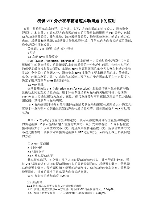
浅谈VTF分析在车辆怠速抖动问题中的应用摘要:某乘用车在怠速开、关空调工况下,方向盘振动加速度较大,影响乘坐舒适性。
本文首先对该车型方向盘振动峰值的可能贡献通道进行VTF分析,包括动力总成悬置系统、排气系统、散热器悬置系统、悬架系统等等。
然后对动力总成前、后悬置和散热器总成悬置进行优化设计后,使得车内方向盘振动幅值降低,乘坐舒适性得到改善。
关键词:VTF 悬置振动优化设计1 引言1.1车辆NVH性能简介NVH(Noise、Vibration、Harshness)是车辆噪声、振动与乘坐舒适性(声振粗糙度)的英文缩写。
这是衡量汽车制造质量的一个综合性问题,它给汽车用户的感受是最直接和最表面的。
车辆的NVH问题是国际汽车业各大整车制造企业和零部件企业关注的问题之一。
影响整车NVH性能的主要来源是发动机、传动系、车身、轮胎与路面。
其中,怠速和加减速工况下车内噪声振动水平在一定程度上决定了用户对整车NVH性能的评价。
1.2 VTF概述振动传递函数VTF(Vibration Transfer Function)主要是指输入激励载荷与输出振动之间的对应函数关系,用于评价车身结构对振动的灵敏度特性。
传统的VTF分析主要通过在动力总成、底盘、排气系统等与车身接附点施加单位力激励,测试或计算得到车内振动响应。
VTF振动传递路径分析是用来评估激励源到振动加速度传递路径大小的工具,它基于一系列输入点到输出位置的声振传递函数矩阵,该传递函数即VTF可以表示为:其中,a表示特定位置的振动加速度。
表示从激励源到目标位置振动加速度的传递函数。
F表示施加在输入位置的激励力。
从公式可以看出,车内目标位置振动响应大小不仅跟激励大小有关,而且跟声振传递函数有关,所以当激励力大小改变困难时,就要求对声振传递函数即VTF进行研究,从结构上找出解决问题的方法。
图2 VTF原理图2 实例分析2.1试验介绍2.1.1整车振动水平某车型怠速开、关空调工况下方向盘振动加速度较大,乘坐舒适性较差。
汽车噪音震动论文英文版
Vehicle noise vibration and harshnessAbstractVehicle noise, vibration and harshness (NVH) is usually the major attribute because of its priority in the design of vehicles. NVH affects the design and manufacture process of a vehicle as higher customer satisfaction are attributed by a good NVH behavior. The research on NVH relies on a variety of computer software to improve and control NVH. In this paper, several vehicle components including rubber dampers and isolators which play an important role in controlling the NVH are presented. A description of source of NVH in a vehicle is shown.Keywords: NVH; rubber damper; isolator; research.1. IntroductionVehicles consist of space vehicles, airplanes, submarines, trains, road, off-road and others [1]. Vehicle noise, vibration, and harshness (NVH) is a major problem in the automobile manufacturing process and affects the customer satisfaction of automobile owners. The researches of vehicle noise, vibration, and harshness (NVH) are not only suitable for the design process of new automobiles, but contribute to improve the comfort and performance of current type of automobiles. Those researches are largely due to the increasing demands of vehicle manufacturers, Original Equipment Manufacturers (OEMs) and customers. The OEMs aim to look for the products that address issues of NVH, reduce vehicle weight, improve stiffness, and are easy to model, lower costs, and are environmentally friendly [2]. Automotive noise, vibration and harshness are the most important issues when the customers assess vehicle quality [1]. On the other hand, some manufacturers refuse to corporate automation into vehicle design, as addressing the issues of NVH which makes vehicles too quiet may pose a threat to the safety of pedestrians [4]. The vehicular noise can act as a warning signal for pedestrians.Some components in the vehicles play important roles in reducing NVH, namely rubber dampers, the power plants, chassis coupling, and elastomeric isolators.Rubber dampers insert between the fins and rubber dampers reduce the amplitude of vibration of fins which are used to speed up the heat transfer from the engine surfaces [3].In vehicles, the engine mounts affect largely the noise, vibration, and harshness comfort. The mounts are used to provide supports for the power plant and to isolate the vibrations of the power plant from the rest of the vehicles [6].A multiplicity of elastomeric isolators is needed, including engine mounts, suspension bushings, and frame and sub frame mounts [5]. Some functional requirements for isolators involve steering, braking, package, and durability, although these desired characteristics conflict frequently.2. The research on NVHFor vehicles, the issue of vibration, noise, and harshness (NVH) exists mainly in the engine, car body, and engine mounts. During the working of these components, they are affected by aerodynamic (NVH), air-conditioning system (NVH) and brake system (NVH). Vehicle NVH emphasis the feeling of human beings for vibration and noise and cannot be measured directly. The research on NVH consists of the comfort of passengers in vehicles and intensity problems of vehicle s’components caused by vibration. The research on the characters of vehicle NVH should concentrate on entire cars and separate entire cars into subsystems, such as engine system, engine mount system and car body system.The issue of vehicle NVH is not caused by relatively several reasons rather than simply one reason. For instance, the noise in the car may be due to the high level of noise of the engine, the pour isolation effect of suspension around the engine, or limited technology of sound-proofing between the car body and power system.There are some basic theories and methodologies helping understand and study the character of NVH.Finite element methods are to separate continuous elastomer into the limited number of units and calculate the system deformation, stress, and dynamics character through the finite element models on the computer. Because of the rapid development of finite element methods and the maturity of relative analysis software, FEM has become an essential method to analyze the character of vehicle NVH. FEM is suitable for the modeling analysis of vehicle body structure vibration and car interior cavity noise. On the other hand, combining FEM with multi-system dynamics to analyze engine mount system can increase the accuracy of dynamic character of the engine mount.BEM is short for the blade element momentum. Compared with FEM, BEM decreases the dimension of questions, making it convenient to handle the issues of unlimited field and establish the efficient network on the computer. The BEM theory is greatly employed for practical engineering application, especially in the field of NVH [16]. The shortage of BEM to address the problem of NVH is low speed of calculation.Experimental transfer path analysis (TPA) is a fairly well established technique for estimating and ranking individual low-frequency noise or vibration contributions via the different structural transmission paths from point-coupled powertrain or wheel suspensions to the vehicle body [11]. Experimental transfer path analysis is a favored technique to investigate further possibilities to fine-tune the rubber components of the engine and wheel suspension with respect to NVH.The experimental transfer path analysis method involves an indirect measurement procedure for estimating operating force components acting at the coupled DOFs (degree of freedom). TPA also involves a direct measurement of all transfer frequency response functions between response in points of interest and points where these forces act [11].Design of experiments method (DOE) can be used to minimize the transmittedengine- induced harshness to the body and improve a vehicle body structure. The DOE method includes factorial and response surface methods. The surface modeling is accomplished for the vehicle body with CATIA and HYPERMESH software which is used to create and optimize the FEA modal. NASTRAN software is used to analyze the modal in a frequency range between 0-50Hz [17, 18].3. The effect of rubber dampers on NVHThe rubber damper is an important type of equipment to reduce noise, vibration, and harshness (NVH), widely being used in a number of machines, vehicles, trains and aircrafts. The popularity of rubber dampers is due to the characteristics of rubber with high visco-elasticity and high elasticity. Compared with steel, elastic deformation of rubber is large and elasticity modulus of rubber is small. As well, rubber is considered as incompressible material.The function of rubber dampers between the fins is to make a compromise between vibration amplitude increases and fin base temperature decreases. Through the research on the effect of rubber dampers on the radiated noise from engine, it is concluded that the effect of the rubber dampers is to reduce engine high frequency noise level, which means the problem of vehicle noise vibration and harshness can be partly handled by using the rubber dampers. Engineers continue to work on the issues of high vehicle noise vibration and harshness when an engine does not rubber dampers with two methods. These two approaches are related to structural noise problems.The first method is to find ways of reducing the sound power by passive means and the other method is to use active control approaches. Compared with active control solutions which may be suitable in the future, passive control should not be ignored as it is useful for high frequency noise [3].Rubber dampers are not the only equipment using rubber in vehicles and some rubber connections are widely employed for structural parts. A change in rubber joint material properties can help evaluate the sensitivity of the full-scale system vehicle noise vibration and harshness (NVH) [7]. A three level modeling approach with a material, a component, and a system level has been introduced to evaluate the sensitivity of the NVH.4. powerplant mounting system NVHThe basic function of engine mount is to support the weight of power train and to isolate the vibration and harshness transmission from engine to body, to segregate the transmission from road surface excitation to power train [8]. As well, in order to lighten the car body, increase power-intensive engine and require vibration, noise, and harshness isolation for passenger cars, the performance of the powerplant mount system need to be improved. Many factors, such as the engine layout state, the supporting positions of chassis mount, the fixed positions on the cylinder of the mount and the layout of surrounding parts, should be considered before the designation of engine mount [9].The responses of the powerplant mounting system to low frequency vibrations are important for improving the NVH in terms of rigidity and damping. Some designs of powerplant mounting system try to handle the issues of NVH by concentrating on the positioning and design of resilient supports. However they fail to consider chassis and suspension system interactions as these designs are based on decoupling rigid body modes from a grounded powerplant mode.Fig.1. Powerplant mounting systemThe traditional engine mount design strategies consider only the rigid body modes of a grounded engine and arrangements of powerplant rigid body mode [6]. When considered as a rigid body, three translational modes and three rotational modes of frame represent the vibration, noise, and harshness (NVH) of powerplant using dynamic decoupling method. In detail, three translational modes are bounce, lateral, and longitudinal vibrations and three rotational modes are called by rotations about pitch, roll and yaw. It is believed that the vibration, noise and harshness (NVH) transferred to the car body structure can be reduced by conditioning the powerplant mounting system such that the powerplant oscillates about the torque axis [10]. The torque roll axis decoupling strategy controls the displacement of the uncoupled blocked powerplant. With less displacement of the powerplant, the level of NVH is reduced [6].The traditional design strategies sometimes may not put the issues of vehicle vibration noise and harshness (NVH) into consideration. With the development of technology and increasing demands of customers for comfort, the manufacturers and automobile companies begin to pay attention to design new powerplant mounting system. The current powerplant mounting strategies examine the rigid-body modes of the power train as it would sit on the mounts attached to the ground and neglect the effect of the chassis. The current engine mount system has achieved the goal that makes sure the driver and the passengers isolate from vibration noise and harshness (NVH) generated by the engine.5. Isolator on NVHElastomeric isolator and hydraulic isolator are widely used in automotive vehicle including shock absorbers, engine mounts and body mounts. Isolators can reduce vibrations and improve the ride performance experienced by drivers and passengers. Noise, vibration and harshness (NVH) are important to the consumer s’acceptance of a vehicle. Isolator s’type, sizing and placement are critical to NVH design [13]. The difference between elastomericisolator and hydraulic isolator is that hydraulic isolators are frequency dependent and elastomeric isolators are independent of frequency. It is largely because they use different mediums to dissipate mechanical energy.A hydraulic isolator connects a vibrating body and an isolated body in a vehicle and consists of a cylinder with two chambers and a piston. An electronic control system is required to cooperate with hydraulic isolator to supply an alternating current of appropriate amplitude and phase to several magnetic coils disposed adjacent to the tuning slug [12]. Matching the isolation frequency with the vibration frequency and adding energy to the vibration isolator to compensate for damping losses is the basic theory how no vibration is transferred from the vibrating body to the isolated body with the help of hydraulic isolator.Fig 4.1 hydraulic isolatorThe elastomeric isolators in the vehicles are separated into two kinds, namely rubber isolator and metal-net isolator. They are used for engines, especially for large power diesel engine. The metal-net isolator with the characters of nonlinear stiffness, large damping and power circumstance adaptability has advantages over rubber isolator and can be used as diesel engine’s mount component.Rubber isolators have been used in NVH control for years. Rubber is hyper elastic material and its suitability as isolator is due to good flexibility and resilience characteristics [14, 15].Rubber isolators cannot be used in low, high temperature, erode and toughcircumstance, e.g. in low temperature, rubber isolators have no isolating effect causing the aggravation of NVH and also can only isolate a single frequency vibration in any circumstance. It is due to the traditional design depending on experience and repeat experiment. Modern rubber isolator is designed with finite element method [14]. A modern rubber isolator is composed of steel and rubber. What differentiate modern isolator rubbers from traditional rubbers is that there are several holes. Those holes can effectively change the static and dynamic characteristics of rubber isolators. As a result, it manages to improve NVH with the improvement of performance of rubber isolatorsFig 4.2 rubber isolatorA metal-net isolator consists of the stainless steel web and the metal wire. When the force is on the stainless steel web, the metal wire slides and results in dry friction damping that absorbs and consumes the energy of system to approach isolating and cushion aims. The isolator’s elastic character is nonlinear, which has higher carrying capacity. Active isolation and passive isolation are two kinds of ways to isolate vibration with the use of metal-net isolator. Active isolation reduces vibration by isolating machine from vibration source and passive isolation relaxes the effect of external vibration [10].Fig 4.3 metal-net isolatorCompared rubber isolator with metal-net isolator, the transfer rate of metal isolator is smaller than that of rubber isolator, which means metal-net isolator has more ability to control NVH and absorb energy.6. ConclusionVehicle vibration, noise and harshness (NVH) has been receiving considerable attention for many years. The main sources of usual NVH are power engine, brake, suspension system, the steering system as well as other hardware of the vehicle. Also, the road NVH and wind NVH has become important issues as they dominate the medium and high speed ranges. In order to improve NVH, the performance of rubber dampers and isolator should be taken measured to improve.The paper gives a brief description of the current research of NVH, several modern methods such as finite element method and blade element momentum have already put into use. These methods greatly increase the accuracy and efficiency when addressing the issues of NVH.Two major components in a vehicle used to control NVH are introduced in the paper, namely rubber damper and isolator. The effect of rubber dampers is to isolate the engine NVH. Isolators are widely used in a vehicle and can be separated as elastomeric isolator and hydraulic isolator. The metal-net isolator has more advantage than rubber dampers. Engine and engine mount are the main sources of NVH. Some traditional engine mounting systems have shortages in design and manufacture.References[1] Mohamad, S. Qatu. “R ecent research on vehicle noise and vibration” , Int. J. Vehicle Noise and Vibration, Vol. 8, No.4, (2012).[2] Anita Carey and Kurt Lilley. Considering and comparing sealant option: a variety of cost-effective solutions, 2002.[3] Singh, O.P., Sreenivasulu, T., Kannan, M. “The effect of rubber dampers on engine’s NVH and thermal performance” , Applied Acoustics 75 17-26 (2014).[4] Nicholas D. Cottrell and Benjamin K. Barton. “The impact of artificial vehicle sounds for pedestrians on driver stress”,Ergonomics, Vol.55, 1476-1486 (2012).[5] Himes, R.S. and David Griffiths. “Future vehicle noise, vibration and harshness requirements for elastomeric isolators”, the Detroit Rubber Group meetin g, Detroit, the USA, September 2000[6] Courteille, E., Leotoing, L., Mortier, F. and Ragnean, E. “New analytical method to evaluate the power plant and chassis coupling in the improvement vehicle NVH”, European Journal of Mechanics A/Solids 24, 929-943 (2005). [7] Stenti, A., Moens, D., Sas, P. and Desmet, W. “A three-level non-deterministic modeling methodology for the NVH behavior of rubber connections” , Journal of Sound and Vibration 329 912-930 (2010).[8] Haran Periyathamby, Michael E. Anderson, David A. Nash and Y. Charles Lu. “NVH characteristics of thermoplastic composite engine covers”, Int. J. Vehicle Noise and Vibration, Vol. 5, No. 3, (2009).[9] Xiangming QIAN. “Research on Structural Design of Vehicle Engine Mount” , IEEE, 978-1-4577-0536-6/11 (2011).[10] Wenbing YAN, Shaozhong JIANG, Yujun CAI, Lizhi WEN and Yue CHEN. “Experimental Study of Engine Mount System’s Vibration Characteristics”, World Congress on Software Engineering, Tianjing, China, 2009.[11] Juha Plunt. “Finding and Fixing Vehicle NVH Problems with Transfer Path Analysis”, the Noise & Vibration Conference, Traverse City, MI, 16-19 May,.2005.[12] Zhixing Li, Shijian Zhu, Jingjun Lou and Simi Tang. “Simulation on Performance of Rubber Isolator Based on ANSYS”IEEE 978-1-4244-9439-2/11 (2011)[13] Chen-Ron Lin and Yu-Der Lee. “Effects of viscoelasticity on rubber vibration isolator design” , Journal of Applied Physics 83, 8027 (1998).[14] Dai, J.C., Hu, Y.P., Liu, D.S. and Long X. “Aerodynamic loads calculation and analysis for large scale wind turbine based on combing BEM modified theory with dynamic stall model” , Renewable Energy 36, 1095-1104 (2011). [15] Shahram Azadi, Mohammad Azadi and Farshad Zahedi. “NVH analysis and improvement of a vehicle body structure using DOE method” , Journal of Mechanical Science and Technology23, 2980-2989 (2009).[16] Shariyat, M. and Djamshidi, P. “Minimizing the Engine-induced Harshness Based on the DOE Method and Sensitivity Analysis of the Full Vehicle NVH Model”, International Journal of Automotive Technology, Vol. 10, No,6, pp. 687-696 (2009)...。
悬架系统的基本原理外文文献翻译、中英文翻译、外文翻译
悬架系统的基本原理外文文献翻译、中英文翻译、外文翻译悬架系统的基本原理悬架系统虽然不是汽车运行不可或缺的部件,但有了它人们可以获得更佳的驾驶感受。
简单来说,它是车身与路面之间的桥梁。
悬架的行程涉及到悬浮于车轮之上的车架,传动系的相对位置。
就像横跨于旧金山海湾之上的金门大桥,它连接了海湾两岸。
去掉汽车上的悬架就像是你做一次冷水潜泳通过海湾一样,你可以平安的渡过整个秋天,但会疼痛会持续几周。
想想滑板吧!它直接接触路面,你可以感受到每一块砖,裂隙及其撞击。
这简直就是一种令人全身都为之震颤的体验。
当轮子滑过路面时,就会在此产生震动、冲击,这种震动的旅程是对你的身体和勇气的检验。
如果你没感到随时都有被掀之势,那么你或许会乐在其中吧!这就是你会在没有悬架的汽车上将会体验到的。
汽车的悬架分为两种基本类型:整体和独立悬架。
整体悬架(也叫刚性梁、刚性轴)是联接车辆上下两部分的一种主要形式。
一如其名,它是用一根金属材料(一般是轴)来连接两侧车轮的。
钢板弹簧在车架之间起到缓冲作用;在两半轴中间装有差速器,允许两侧的轮子以不同的角速度旋转。
整体式悬架的车辆在行进中,由于两侧的车轮共用一根轴,因此当某一侧车轮跳动时,另一侧也会随之运动。
它们的反馈结果就像是一个整体。
可以想象到,这不可能有舒适的驾驶体验。
虽然可以借助于弹簧来衰减猛烈的震动,但仍然存在较强的震动。
那么既然如此,为什么还要使用这种悬架呢?第一,它很坚固,由于采用了一体化的结构,定轴式悬架系统具有着其他方式悬架不可替代的承载能力。
它们经常应用于行驶于较差路况的车辆。
你可以在卡车和重载车辆上见到它。
一种由固定轴式悬架变形系统叫做TIB悬架系统(或叫半固定轴式)。
在这种结构中,有两根刚性轴而非一根。
这种设计可兼得较大的刚性和较好的韧性,通常用于轻卡的前悬。
另一种常见的悬架系统是独立悬架,它由两个独立的“桥”连接车轮。
这种结构可以提供最舒适的乘坐环境,因此多用于乘用车、小型货车和其他小型车辆。
某汽车怠速抖动问题分析与改进
9510.16638/ki.1671-7988.2018.18.033某汽车怠速抖动问题分析与改进黄秋生(安徽江淮汽车集团股份有限公司,安徽 合肥 230601)摘 要:文章首先论述了汽车怠速振动的原理,汽车动力总成的振动模型,模态频率和解耦率的试验方法。
继而对问题车辆的动力总成及悬置系统的缺陷进行计算分析。
通过模拟计算,确定优化后的方案满足匹配要求。
最终通过试验测试结果确定优化方案可行。
关键词:NVH ;模态频率;解耦率;怠速振动中图分类号:U471.2 文献标识码:B 文章编号:1671-7988(2018)18-95-03Analysis and optimization on idling vibration of same carHuang Qiusheng( Anhui Jianghuai Automobile Group Co., Ltd., Anhui Hefei 230601 )Abstract: This paper firstly introduce the principle of automobile idling vibration, the vibration model of powertrain, and how to calculating the mode frequency and the decoupling rate of the six freedom degrees. Then, we analyze the indication of the powertrain and suspension system by calculating the mode frequency and the decoupling rate of the six freedom degrees. The optimization scheme which we have accepted by simulation has been provided to be effective after testing. Keywords: NVH; Modal frequency; Decouping rate; Idle vibrationCLC NO.: U471.2 Document Code: B Article ID: 1671-7988(2018)18-95-031 汽车的怠速振动在发动机的爆发压力和上下往复运动不平衡力的作用下,引起动力总成的振动,并经过动力总成悬置,传递到车身,引起车身低频振动,即为怠速振动。
- 1、下载文档前请自行甄别文档内容的完整性,平台不提供额外的编辑、内容补充、找答案等附加服务。
- 2、"仅部分预览"的文档,不可在线预览部分如存在完整性等问题,可反馈申请退款(可完整预览的文档不适用该条件!)。
- 3、如文档侵犯您的权益,请联系客服反馈,我们会尽快为您处理(人工客服工作时间:9:00-18:30)。
附录附录AAn Analysis of Idling Vibration for a Frame StructuredVehicleABSTRACTA finite element model for an entire frame-structured sports utility vehicle was made to evaluate the characteristics of the idling vibrations for the vehicle. The engine exciting forces were determined by Souma's method to simulate the idling vibrations. The modeling of the power plant and the entire vehicle was verified by the reasonable agreement of the experiment and calculation results. Attention was focused on the frequency of the first-order vertical bending mode for the frame. It has become clear that the idling vibration level of the vehicle is lowered by decreasing the frequency of the first-order frame bending mode. INTRODUCTIONOne of the defects of a diesel vehicle, which has fuel and economical efficiency, is idling vibration for a vehicle body. In a diesel engine, sharp pressure rise caused by the generation of the thermal energy affects the pistons. In the crank system, which converts the linear motion into the rotary motion, two types of reaction forces excite the engine block: the reaction caused by the alternation of the velocity vector in each moving parts, and by the non-uniform rotary motion generated by the finite number of cylinders. The forces transmit to an engine block, an engine foot, a rubber engine mount, a frame, a rubber cab-mount, and then a vehicle body, which make occupants uncomfortable.The idling vibration for large-sized commercial vehicles was estimated at the early development stage, and the measures against the vibration were taken by simulating the engine exciting forces with Souma…s method,and entering them to a vehicle model.In this paper, the idling vibration was determined by entering the engine exciting forces to the vehicle model, which was made of the finite element of the frame and the body for a small-sized recreational vehicle (RV). Also in this paper, how the natural modes for the frame changes in the vehicle condition is analyzed, and it was indicated that the natural frequency of the first-order vertical bending for the frame had a significant effect. ANALYSIS OF THE VEHICLE BODY VIBRATIONFigure 1 shows the results of analyzing the frequencies of the acceleration in vertical vibration generated on the seat rail while idling in small-sized RV powered by 4-cylinder diesel engine. The main part of the idling vibration is the second-order engine rotation. The 0.5th, 1st, and 1.5th -orders are also critical. However, these orders are caused by the varied combustion between cylinders. A measure against the varied combustion can be expected by improving the injection system. In this research, only 24Hz of the second-order at the idling rotation speed of 720rpm is focused on as a measure in the vehicle structure. Besides, a measure for lowering the vibration is studied because the vertical vibration on seats has a great damaging effect on human sense.IDENTIFICATION OF THE ENGINE EXCITING FORCEThere are three paths for the engine to excite vibration to a vehicle body: through an engine mount, a driving system, and a tail pipe. In this paper, the path through an engine mount, which has a greatest effect, is studied. The various types of methods to identify the exciting force through an engine mount are known. In this paper, Souma‟s method is used. OUTLINE OF SOUMA’S METHODThe cause of the exciting force to an engine block in the controversial frequency domain of the idling vibration is considered. First, the combustion pressure that acts on the pistons is considered to cause the vibration. However, assuming that a piston crankshaft does not move with a flywheel and an engine block fixed in some way, the engine components are supposed to be completely rigid in this frequency domain. In this situation, the engine block will not vibrate if the piston crankshaft does not move in spite of the rapid pressure rise in a combustion chamber due to the diesel combustion.Accordingly, the direct cause of the engine block vibration is not the combustion pressure but the reaction against the piston crankshaft movement. To determine the exciting force to the engine block, the reaction forces against the movement of the mass (mainly in crank system and piston system), which works inside and outside of the engine block, may be calculated.In So uma‟s method, the non-uniform rotary motion in the crank system is found by measuring the pulse generated in a ring gear of the flywheel. Then, the vertical motion in the connected piston system is calculated to determine the exciting force to the engine block using each mass specification value.VERIFICATION OF THE ACCURACY IN THE EXCITING FORCEThe exciting forces are added at the point corresponding to the crankshaft on the entire vehicle model (described later). The vibration on the head cover and the right engine foot, which the exciting forces mostly affect, is estimated. The results of comparing the calculation with the experiment are shown in Figure 2 and 3. In Figure 2 and 3, 5 types of calculated results are shown considering the idling rotation speed changes.In Figure 2 and 3, the calculation and the experiment are identified around 24 Hz, 48 Hz, and 72 Hz of 2nd, 4th, and 6th-orders at the speed of 720 rpm. The data of the left engine foot, which is not shown in this paper, is also almost identified. In this frequency domain, as for the vibration, the engine and the vehicle body are insulated by the engine mount. The body hardly affects the engine vibration. As the data of the experiment and the calculation is identified in this domain, the power plant modeling and the exciting force can be considered reasonable.However, around 12 Hz of 1st-orders, data is not much identified. In this frequency domain, the vibration of the engine and the vehicle body are mutually coupled through the engine mount. Therefore, the accuracy of the vehicle body model has a damaging effect. IMPROVEMENT OF THE MEASURING ACCURACY IN LOW-FREQUENCY VIBRATIONThe engine exciting force was determined using Souma‟s method, and the vibration in each part of the engine was calculated by adding the exciting force. So far, however, the calculated data has not been much identified with the actual measurement. Therefore, the accuracy of the actual measurement is improved. In the surface vibration of the engine, the low-frequency vibration, which causes the idling vibration, and the high-frequency vibration, which causes noise, are mixed. When the mixed vibration is measured with a piezo element acceleration pickup, the high-frequency order is emphasized and the target low-frequency order becomes relatively small. For example, the measured acceleration to time waveform for the vertical vibration in the right engine foot is shown in Figure 4.In this paper, a strain gage acceleration pickup, which measures force acting on the inner weight by strain, is used. This device, which is larger than a piezo element acceleration pickup, is more sensitive to the acceleration. Besides, silicon oil is filled inside to protect the detecting parts in this device, which mechanically blocks off the high-frequency order. The measured acceleration to time waveform for the vertical vibration with the device is shown in Figure 5. Compared with Figure 4, Figure 5 shows only thelow-frequency order although the same area was measured. In this way, the high-frequency order is blocked off, which results in the higher sensitivity with the device. This time, the device, which measures the acceleration ranging from 0 to 20m/s2,was used. This device is easily calibrated using G-forces because it has the higher sensitivity. When a piezo element acceleration pickup was used, the differences between the calculation and the experiment were 20-40% in the main order of the vibration, and a few times in other orders. Therefore, the principle of Souma‟s method using a piez o element accelerationpickup has been in doubt. However, the data of the experiment and the calculation has been identified as shown in Figure 2 and 3 since a strain gage acceleration pickup, which has been used in the experiment of movement performance, was used for an engine.Fig. 1 Seat rail vertical vibration Fig. 2 Head cover lateral vibrationFig. 3 Right engine foot vertical vibration Fig.4 Measurement with piezo element acceleration pickup ENTIRE VEHICLE MODELFigure 6 shows the body model. Interior and exterior equipments such as doors and seat are added in the form of 85 mass points to the main structure modeling detailed with sheet metal finite elements. The grid points are 61,912. Figure 7 shows the model where a frame, a suspension, and an engine are combined, and a fuel tank and a bumper is added in the form of concentrated mass. The grid points are 39,262.Combining the models shown in Figure 6 and 7 using cabmount makes the entire vehicle model. Total grid points mounts to 101,174. The calculation time is 3,293 seconds using IBMSP2, MSC/NASTRAN Version 70.5.2. The calculating method is package calculation. If the model becomes on larger scale, the model must be calculated by the block structure.Figure 8 shows the frequency response function, indicating the responses of the frame with the right back engine mount after exciting the driver‟s seat rail. In the frequency ranging from 20 to 30 Hz, which is required for the analysis, the data of the experiment is qualitatively identified with that of the calculation.Fig. 5 Measurement with strain gage acceleration pickup Fig. 6 Body modeFig.7 Frame,power plant and suspension model Fig.8 Frequency response function CORRELATION ANALYSIS OF THE MODESFrom the viewpoint of vibration characteristics, it can be considered that an entire vehicle is insulated by the engine mount and the cabmount, which have relatively small spring constants, although the insulation is not complete. When the entire vehicle is divided into block structures by each insulating mount and suspension, the body has 4 block structures:(1) Block where interior equipment is added in the form of concentrated mass to the body as shown in Figure 6, which is described as “body”, hereafter.(2) Block where the fuel tank and the bumper are added in the from of concentrated mass to the frame as shown in Figure 7, which is described as “frame,” hereafter.(3) Power plant(4) SuspensionAmong the above block structures, (1) body and (2) frame have the natural frequency around 24 Hz in the idling vibration. The vibration characteristics for the body, the frame and the entire vehicle model are compared and investigated.COMPARISON OF NATURAL FREQUENCYFigure 9 shows the distribution of the natural vibration frequency in each block structure and in the vehicle condition. The frame has 17 natural modes below 50Hz. In Figure 7, the model mounting a power plant and a suspension on the frame, is called Y chassis, which has 35 natural modes below 50 Hz. Y chassis makes the entire vehicle model by mounting the body, which has 94 natural modes below 50 Hz.When the number of natural modes of Y chassis is added to 61 natural modes of the body, total number of the modes amounts to 96. The number of the natural modes of the entire vehicle model (94) is less than the above total number by 2 modes. This is because 2 natural modes became above 50 Hz by combining Y chassis and the body, as the result of analyzing the mode correlation described later.Fig. 9 Natural modes in frequency domain附录B具有车架结构车辆的怠速震动分析摘要建立全车架结构SUV的有限元模型,用来评价车辆的怠速震动特性。