模具设计与制造毕业论文中英文资料外文翻译文献
模具毕业设计外文翻译(英文+译文)
Injection MoldingThe basic concept of injection molding revolves around the ability of a thermoplastic material to be softened by heat and to harden when cooled .In most operations ,granular material (the plastic resin) is fed into one end of the cylinder (usually through a feeding device known as a hopper ),heated, and softened(plasticized or plasticized),forced out the other end of the cylinder, while it is still in the form of a melt, through a nozzle into a relatively cool mold held closed under pressure.Here,the melt cools and hardens until fully set-up. The mold is then opened, the piece ejected, and the sequence repeated.Thus, the significant elements of an injection molding machine become: 1) the way in which the melt is plasticized (softened) and forced into the mold (called the injection unit);2) the system for opening the mold and closing it under pressure (called the clamping unit);3) the type of mold used;4) the machine controls.The part of an injection-molding machine, which converts a plastic material from a sold phase to homogeneous seni-liguid phase by raising its temperature .This unit maintains the material at a present temperature and force it through the injection unit nozzle into a mold .The plunger is a combination of the injection and plasticizing device in which a heating chamber is mounted between the plunger and mold. This chamber heats the plastic material by conduction .The plunger, on each stroke; pushes unbelted plastic material into the chamber, which in turn forces plastic melt at the front of the chamber out through the nozzleThe part of an injection molding machine in which the mold is mounted, and which provides the motion and force to open and close the mold and to hold the mold close with force during injection .This unit can also provide other features necessary for the effective functioning of the molding operation .Movingplate is the member of the clamping unit, which is moved toward a stationary member. the moving section of the mold is bolted to this moving plate .This member usually includes the ejector holes and mold mounting pattern of blot holes or “T” slots .Stationary plate is the fixed member of the clamping unit on which the stationary section of the mold is bolted .This member usually includes a mold-mounting pattern of boles or “T” slots. Tie rods are member of the clamping force actuating mechanism that serve as the tension member of the clamp when it is holding the mold closed. They also serve as a gutted member for the movable plate .Ejector is a provision in the clamping unit that actuates a mechanism within the mold to eject the molded part(s) from the mold .The ejection actuating force may be applied hydraulically or pneumatically by a cylinder(s) attached to the moving plate, or mechanically by the opening stroke of the moving plate.Methods of melting and injecting the plastic differ from one machine to another and are constantly being implored .conventional machines use a cylinder and piston to do both jobs .This method simplifies machine construction but makes control of injection temperatures and pressures an inherently difficult problem .Other machines use a plasticizing extruder to melt the plastic and piston to inject it while some hare been designed to use a screw for both jobs :Nowadays, sixty percent of the machines use a reciprocating screw,35% a plunger (concentrated in the smaller machine size),and 5%a screw pot.Many of the problems connected with in ejection molding arise because the densities of polymers change so markedly with temperature and pressure. thigh temperatures, the density of a polymer is considerably cower than at room temperature, provided the pressure is the same.Therefore,if molds were filled at atmospheric pressure, “shrinkage” would make the molding deviate form the shape of the mold.To compensate for this poor effect, molds are filled at high pressure. The pressure compresses the polymer and allows more materials to flow into the mold, shrinkage is reduced and better quality moldings are produced.Cludes a mold-mounting pattern of bolt holes or “T” slots. Tie rods are members of the clamping force actuating mechanism that serve as the tension members of clamp when it is holding the mold closed. Ejector is a provision in the calming unit that actuates a mechanism within the mold to eject the molded part(s) form the mold. The ejection actuating force may be applied hydraulically or pneumatically by a cylinder(s) attached to the moving plate, or mechanically by the opening stroke of the moving plate.The function of a mold is twofold: imparting the desired shape to the plasticized polymer and cooling the injection molded part. It is basically made up of two sets of components: the cavities and cores and the base in which the cavities and cores are mounted. The mold ,which contains one or more cavities, consists of two basic parts :(1) a stationary molds half one the side where the plastic is injected,(2)Moving half on the closing or ejector side of the machine. The separation between the two mold halves is called the parting line. In some cases the cavity is partly in the stationary and partly in the moving section. The size and weight of the molded parts limit the number of cavities in the mold and also determine the machinery capacity required. The mold components and their functions are as following:(1)Mold Base-Hold cavity (cavities) in fixed, correctposition relative to machine nozzle.(2)Guide Pins-Maintain Proper alignment of entry into moldinterior.(3)Spree Bushing (spree)-Provide means of entry into moldinterior.(4)Runners-Conroy molten plastic from spree to cavities.(5)Gates-Control flow into cavities.(6)Cavity (female) and Force (male)-Control the size,shape and surface of mold article.(7)Water Channels-Control the temperature of mold surfacesto chill plastic to rigid state.(8)Side (actuated by came, gears or hydrauliccylinders)-Form side holes, slots, undercuts and threaded sections.(9)Vent-Allow the escape of trapped air and gas.(10)Ejector Mechanism (pins, blades, stripper plate)-Ejectrigid molded article form cavity or force.(11)Ejector Return Pins-Return ejector pins to retractedposition as mold closes for next cycle.The distance between the outer cavities and the primary spree must not be so long that the molten plastic loses too much heat in the runner to fill the outer cavities properly. The cavities should be so arranged around the primary spree that each receives its full and equal share of the total pressure available, through its own runner system (or the so-called balanced runner system).The requires the shortest possible distance between cavities and primary sprue, equal runner and gate dimension, and uniform culling.注射成型注射成型的基本概念是使热塑性材料在受热时熔融,冷却时硬化,在大部分加工中,粒状材料(即塑料树脂)从料筒的一端(通常通过一个叫做“料斗”的进料装置)送进,受热并熔融(即塑化或增塑),然后当材料还是溶体时,通过一个喷嘴从料筒的另一端挤到一个相对较冷的压和封闭的模子里。
Mold-design-and-manufacture模具设计与制造大学毕业论文外文文献翻译及原文
毕业设计(论文)外文文献翻译文献、资料中文题目:模具设计与制造文献、资料英文题目:Mold design and manufacture 文献、资料来源:文献、资料发表(出版)日期:院(部):专业:班级:姓名:学号:指导教师:翻译日期: 2017.02.14Mold design and manufactureThe mold is the manufacturing industry important craft foundation in our country,the mold manufacture belongs to the special purpose equipment manufacturing industry. Although China very already starts to make the mold and the use mold but long-term has not formed the industry. Chinese mold industry only then drives into the development speed way. Recent years not only the state-owned mold enterprise had the very big development the three investments enterprise the villages and towns individual the mold enterprises development also quite rapid. Although the Chinese mold industrial development rapid but compares with the demand obviously falls short of demand its main gap concentrates precisely to large-scale is complex the long life mold domain. As a result of in aspect and so on mold precision life manufacture cycle and productivity。
模具设计专业毕设外文翻译译文(DOC)

本科毕业设计(论文)外文翻译(附外文原文)学院:机械与控制工程学院课题名称:复杂阶梯形圆筒件拉深有限元分析专业(方向):机械设计制造及其自动化(模具设计与制造)班级:学生:指导教师:日期:拉伸模设计中拉伸壁起皱的分析摘要本文研究带有斜度的方形盒和带有阶梯的方形盒的拉深中发生的起皱现象。
这两种类型的起皱现象有一个共同的特征:全都发生在相对无支撑、无压边的拉深壁处。
在带有斜度的方形盒的拉深中,常受到工序参数的影响,例如:模具的间隙值和压边力等,所以常用有限元模拟的方法来研究分析起皱的发生。
模拟的结果表明模具的间隙值越大,起皱现象就越严重,而且增加压边力也不能抑制和消除起皱现象的发生。
在带有阶梯的方形盒拉深的起皱现象分析中,常通过实际生产中一种近似的几何结构来研究、试验。
当凸模与阶梯边缘之间的金属板料在拉深时分布并不均衡,就会在侧壁发生起皱现象。
为了消除起皱现象的发生,一个最优的模具设计常采用有限元的方法进行分析。
模拟的结果和起皱试验论证了有限元分析的准确性,并且表明了在拉深模具设计中使用有限元方法分析的优越性。
关键词:侧壁起皱;拉深模;带有阶梯的方形盒;带有斜度的方形盒1 引言起皱是金属板料成形中常见的失效形式之一。
由于功能和视觉效果的原因,起皱通常是不能为零件制品所能接受的。
在金属板料成形加工中通常存在三种类型的起皱现象:法兰起皱;侧壁起皱和由于残余压应力在未变形区产生的弹性变形。
在冲压复杂形状的时候,拉深壁起皱就是在模具型腔中形成的褶皱。
由于金属板料在拉深壁区域内相对无支撑,因此,消除拉深壁起皱比抑制法兰起皱要难得多。
我们知道在不被支撑的拉深壁区域中材料的外力拉深可以防止起皱,这可以在实践中通过增加压边力而实现,但是运用过大的拉深力会引起破裂失效。
因此,压边力必须控制在一定的范围内,一方面可以抑制起皱,另一方面也可以防止破裂失效。
合适的压边力范围是很难确定的,因为起皱在拉深零件的中心区域以一个复杂的形状形成,甚至根本不存在一个合适的压边力范围。
模具制造科学外文文献翻译、模具类中英文翻译、外文翻译
英文翻译The Science of Die MakingThe traditional method of making large automotive sheet metal dies by model building and tracing has been replaced by CAD/CAM terminals that convert mathematical descriptions of body panel shapes into cutter paths.Teledyne Specialty Equipment’s Efficient Die and Mold facility is one of the companies on the leading edge of this transformation.by Associate EditorOnly a few years ago,the huge steel dies requited for stamping sheet metal auto body panels were built by starting with a detailed blueprint and an accurate full-scale master model of the part. The model was the source from which the tooling was designed and produced.The dies,machined from castings,were prepared from patterns made by the die manutacturers or somethimes supplied bythe car maker.Secondary scale models called”tracing aids”were made from the master model for use on duplicating machines with tracers.These machines traced the contour of the scale model with a stylus,and the information derived guided a milling cutter that carved away unwanted metal to duplicate the shape of the model in the steel casting.All that is changing.Now,companies such as Teledyne Specialty Equipment’s Effi cient Die and Mold operation in Independence,OH,work from CAD data supplied by customers to generate cutter paths for milling machines,which then automatically cut the sheetmetal dies and SMC compression molds.Although the process is uesd to make both surfaces of the tool, the draw die still requires a tryout and “benching” process.Also, the CAD data typically encompasses just the orimary surface of the tool,and some machined surfaces, such as the hosts and wear pads, are typically part of the math surface.William Nordby,vice president and business manager of dies and molds at Teledyne,says that “although no one has taken CAD/CAM to the point of building the entire tool,it will eventually go in that direction because the “big thrdd”want to compress cycle times and are trying to cut the amount of time that it takes to build the tooling.Tryout, because of the lack of development on the design end,is still a very time-consuming art,and vety much a trial-and-error process.”No More Models and Tracing AidsThe results to this new technology are impressive. For example, tolerances are tighter and hand finishing of the primary die surface with grinders has all but been eliminated. The big difference, says Gary Kral, Teledyne’s director of engineering, is that the dimensional control has radically improved. Conventional methods of making plaster molds just couldn’t hold tolerances because of day-to-day temperature and humidity variations.”For SMC molds the process is so accurate , and because there is no spring back like there is when stamping sheet metal, tryouts are not always required.SMC molds are approved by customers on a regulate basis without ever running a part .Such approvals are possible because of Teledyne’s ability to check the toolsurface based on mathematical analysis and guarantee that it is made exactly to the original design data.Because manual trials and processes have been eliminated, Teledyne has been able to consider foreign markets.” The ability to get a tool approved based on the mathe gives us the opportunity to compete in places we wouldn’t have otherwise,” says Nordby.According to Jim Church, systems manager at Teledyne, the company used to have lots of pattern makers ,and still has one model maker.” But 99.9 percent of the company’s work now is from CAD data. Instead of model makers, engineers work in front of computer monitors.”He says that improvenents in tool quality and reduction in manufacturing time are significant. Capabilities of the process were demonstrated by producing two identical tools. One was cut using conventional patterns and tracing mills, and the other tool was machined using computer generated cutting paths. Although machining time was 14 percent greater with the CAM-generated path, polishing hours were cut by 33 percent. In all ,manufacturing time decreased 16.5 percent and tool quality increased 12 percent.Teledyne’s CAD/CAM system uses state-of-the-art software that allows engineers to design dies and molds, develop CNC milling cutter paths and incorporate design changes easily. The system supports full-color, shaded three-dimensional modeling on its monitors to enhance its design and analysis capabilities. The CAD/CAM system also provides finite element analysis that can be used to improve the quality of castings , and to analyze the thermal properties of molds. Inputs virtually from any customer database can be used either directly or through translation.CMM Is CriticalTeledyne’s coordinate measuring machine(CMM),says’ Church,”is what has made a difference in terms of being able to move from the traditional manual processes of mold and die making to the automated system that Teledyne uses today.”The CMM precisely locates any point in a volume of space measuring 128 in, by 80 in, by 54 in, to an accuracy of 0.0007 in. It can measure parts, dies and molds weighing up to 40 tons. For maximum accuracy,the machine is housed in an environmentally isolated room where temperature is maintained within 2 deg.F of optimum. To isolate the CMM from vibration, it is mounted on a 100-ton concrete block supported on art cushions.According to Nordby, the CMM is used not only as a quality tool, but also as a process checking tool. “ As a tool goes through the shop, it is checked several times to validate the previous operation that was performed.” For example, after the initial surface of a mold is machined and before any finish work is done, it is run through the CMM for a complete data check to determine how close the surface is to the required geometry.The mold is checked with a very dense pattern based on flow lines of the part. Each mold is checked twice, once before benching and again after benching. Measurements taken from both halves of the mold are used to calculate theoretical stock thickness at full closure of the mold to verify its accuracy with the CAD design data.Sheet Metal Dies Are Different“Sheet metal is a different ballgame,” says Nordby, “because you have the issue of material springback and the way the metal forms in the die. What happens in the sheet metal is that you do the same kinds of things for the male punch as you would with SMC molds and you ensure that it is 100 percent to math data. But due to machined surface tolerance variations, the female half becomes the working side of the tool. And there is still a lot of development required after the tool goes into the press. The math generated surfaces apply primarily to the part surface of the tool.”EMS Tracks the Manufacturing ProcessTeledyne’s business operations also are computerized and carried over a network consisting of a V AX server and PC terminals. IMS (Effective Management Systems) software tracks orders, jobs in progress, location of arts, purchasing, receiving, and is now being upgraded to include accounting functions.Overall capabilities of the EMS system include bill-of-material planning and control, inventory management, standard costing, material history, master production scheduling, material requirements planning, customer order processing, booking and sales history, accounts receivable, labor history, shop floor control, scheduling, estimating, standard routings, capacity requirements planning, job costing, purchasing and receiving, requisitions, purchasing and receiving, requisitions, purchasing history and accounts payable.According to Frank Zugaro, Teledyne’s scheduling manager, the EMS software was chosen because of its capabilities in scheduling time and resources in a job shop environment. All information about a job is entered into inventory management to generate a structured bill of material. Then routes are attached to it and work orders are generated.The system provides daily updates of data by operator hour as well as a material log by shop order and word order. Since the database is interactive, tracking of materials received and their flow through the build procedure can be documented and cost data sent to accounting and purchasing.Gary Kral, Teledyne’s director of engineering, says that EMS is really a tracking device, and one of the systems greatest benefits is that it provides a documented record of everything involving a job and eliminates problems that could arise from verbal instructions and promises. Kral says that as the system is used more, they are finding that it pays to document more things to make it part of the permanent record. It helps keep them focused.模具制造科学传统的通过制造模具加工大型板材的方法已经被可以把实体的形状信息转换为切削路径的CAD/CAM所取代了。
塑料模具毕业设计中英文对照资料外文翻译文献
中英文对照资料外文翻译文献一个描述电铸镍壳在注塑模具的应用的技术研究摘要:在过去几年中快速成型技术及快速模具已被广泛开发利用. 在本文中,使用电芯作为核心程序对塑料注射模具分析. 通过差分系统快速成型制造外壳模型. 主要目的是分析电铸镍壳力学特征、研究相关金相组织,硬度,内部压力等不同方面,由这些特征参数以生产电铸设备的外壳. 最后一个核心是检验注塑模具.关键词:电镀;电铸;微观结构;镍1. 引言现代工业遇到很大的挑战,其中最重要的是怎么样提供更好的产品给消费者,更多种类和更新换代问题. 因此,现代工业必定产生更多的竞争性. 毫无疑问,结合时间变量和质量变量并不容易,因为他们经常彼此互为条件; 先进的生产系统将允许该组合以更加有效可行的方式进行,例如,如果是观测注塑系统的转变、我们得出的结论是,事实上一个新产品在市场上具有较好的质量它需要越来越少的时间快速模具制造技术是在这一领域, 中可以改善设计和制造注入部分的技术进步. 快速模具制造技术基本上是一个中小型系列的收集程序,在很短的时间内在可接受的精度水平基础上让我们获得模具的塑料部件。
其应用不仅在更加广阔而且生产也不断增多。
本文包括了很广泛的研究路线,在这些研究路线中我们可以尝试去学习,定义,分析,测试,提出在工业水平方面的可行性,从核心的注塑模具制造获取电铸镍壳,同时作为一个初始模型的原型在一个FDM设备上的快速成型。
不得不说的是,先进的电铸技术应用在无数的行业,但这一研究工作调查到什么程度,并根据这些参数,使用这种技术生产快速模具在技术上是可行的. 都产生一个准确的,系统化使用的方法以及建议的工作方法.2 制造过程的注塑模具薄镍外壳的核心是电铸,获得一个充满epoxic金属树脂的一体化的核心板块模具(图1)允许直接制造注射型多用标本,因为它们确定了新英格兰大学英文国际表卓华组织3167标准。
这样做的目的是确定力学性能的材料收集代表行业。
该阶段取得的核心[4],根据这一方法研究了这项工作,有如下:a,用CAD系统设计的理想对象b模型制造的快速成型设备(频分多路系统). 所用材料将是一个ABS塑料c一个制造的电铸镍壳,已事先涂有导电涂料(必须有导电).d无外壳模型e核心的生产是背面外壳环氧树脂的抗高温与具有制冷的铜管管道.有两个腔的注塑模具、其中一个是电核心和其他直接加工的移动版. 因此,在同一工艺条件下,同时注入两个标准技术制造,获得相同的工作。
模具外文翻译外文文献英文文献注塑模

模具外文翻译外文文献英文文献注塑模The Injection Molding1、The injection moldingInjection molding is principally used for the production of the thermoplastic parts,although some progress has been made in developing a method for injection molding some thermosetting materials.The problem of injection a method plastic into a mold cavity from a reservoir of melted material has been extremely difficult to solve for thermosetting plastic which cure and harden under such conditions within a few minutes.The principle of injection molding is quite similar to that of die-casting.The process consists of feeding a plastic compound in powered or granular form from a hopper through metering and melting stages and then injecting it into a mold.After a brief cooling period,the mold is opened and the solidified part ejected.Injection-molding machine operation.The advantage of injection molding are:(ⅰ)a high molding speed adapter for mass production is possible;(ⅱ)there is a wide choice of thermoplastic materials providing a variety of useful properties;(ⅲ)it is possible to mold threads,undercuts,side holes,and large thin section.2、The injection-molding machineSeveral methods are used to force or inject the melted plastic into the mold.The most commonly used system in the larger machines is the in-line reciprocating screw,as shown in Figure 2-1.The screw acts as a combination injection and plasticizing unit.As the plastic is fed to the rotating screw,it passes through three zones as shown:feed,compression,and metering.After the feed zone,the screw-flight depth is gradually reduced,force theplastic to compress.The work is converted to heat by conduction from the barrel surface.As the chamber in front of the screw becomes filled,it forces the screw back,tripping a limit switch that activates a hydraulic cylinder that forces the screw forward and injects the fluid plastic into the closed mold.An antiflowback valve presents plastic under pressure from escaping back into the screw flight.The clamping force that a machine is capable of exerting is part of the size designation and is measured in tons.A rule-of-thumb can be used to determine the tonnage required for a particular job.It is based on two tons of clamp force per square inch of projected area.If the flow pattern is difficult and the parts are thin,this may have to go to three or four tons.Many reciprocating-screw machines are capable of handing thermosetting plastic materials.Previously these materials were handled by compression or transfer molding.Thermosetting materials cure or polymerize in the mold and are ejected hot in the range of 375°C~410°C.T hermosetting parts must be allowed to cool in the mold in order or remove them without distortion. Thus thermosetting cycles can be faster.Of course the mold must be heated rather than chilled,as with thermoplastics.3、Basic Underfeed MouldA simple mould of this type is shown in Figure3-1,and the description of the design and the opening sequence follows.The mould consists of three basic parts,namely:the moving half,the floating cavity plate and the feed plate respectively.The moving half consists of The moving mould plate assembly,support block,backing plate,ejector assembly and the pin ejection system.Thus the moving half in this design is identical with the moving half of basic moulds.The floating cavity plate,which may be of the integer or insert-bolster design,is located on substantial guide pillars(not shown)fitted in the feed plate.These guide pillars must be of sufficient length to support the floating cavity plate over its full movement and still project to perform the function of alignment between the cavity and core when the mould is being closed.Guide bushes are fitted into the moving mould plate and the floating cavity plate respectively.The maximum movement of the floating cavity plate is controlled by stop or similar device.The moving mould plate is suitably bored to provide a clearance for the stop bolt assembly.The stop bolts must be long enough to provide sufficient space between the feed plate and the floating cavity plate for easy removal of the feed system.The minimum space provide for should be 65mm just sufficient for an operator to remove the feed system by hand if necessary.The desire operating sequence is for the first daylight to occur between the floating cavity plate.This ensures the sprue is pulled from the sprue bush immediately the mouldis opened.T o achieve this sequence,springs may be incorporated between the feed plate and the floating cavity plate.The springs should be strong enough to give an initial impetus to the floating cavity plate to ensure it moves away with the moving half.It is normal practice to mount the springs on the guide pillars(Figure3-2)and accommodate them in suitable pocket in the cavity plate.The major part of the feed system(runner and sprue)is accommodated in the feed plate to facilitate automatic operation,the runner should be of a trapezoidal form so that once it is pulled from the feed plate is can easily beextracted.Note that if a round runner is used,half the runner is formed in the floating cavity plate,where it would remain,and be prevented from falling or being wiped clear when the mould is opened.Now that we have considered the mould assembly in the some detail,we look at the cycle of operation for this type of mould.The impressions are filled via the feed system(Figure3-1(a))and after a suitable dwell period,the machine platens commence to open.A force is immediately exerted by the compression springs,which cause the floating cavity plate to move away with the moving half as previously discussed.The sprue is pulled from the sprue bush by the sprue puller.After the floating cavity plate has moved a predetermined distance,it is arrested by the stop bolts.The moving half continues to move back and the moldings,having shrunk on to the cores,are withdrawn from the cavities.The pin gate breaks at its junction with the runner(Figure3-1(b)).The sprue puller,being attached to the moving half,is pulled through the floating cavity plate and thereby release the feed system which is then free to fall between the floating cavity plate and the feed plate.The moving half continues to move back until the ejector system is operated and the moldings are ejected (Figure3-1(c)).When the mould is closed,the respective plates are returned to their molding position and the cycle is repeated.4、Feed SystemIt is necessary to provide a flow-way in the injection mould to connect the nozzle(of the injection machine)to each impression.This flow-way is termed the feed system.Normally thefeed system comprises a sprue,runner and gate.These terms applyequally to the flow-way itself,and to the molded material which is remove from the flow-way itself in the process of extracted the molding.A typical feed system for a four-impression,two plate-type mould is shown in Figure4-1.It is seen that the material passes through the sprue,main runner,branch runner and gate before entering the impression.As the temperature of molten plastic is lowered which going through the sprue and runner,the viscosity will rise;however,the viscosity is lowered by shear heat generated when going through the gate to fill the cavity.It is desirable to keep the distance that the material has to travel down to a minimum to reduce pressure and heat losses.It is for this reason that careful consideration must be given to the impression layout gate’s design.4.1.SprueA sprue is a channel through which to transfer molten plastic injected from the nozzle of the injector into the mold.It is a part of sprue bush,which is a separate part from the mold.4.2.RunnerA runner is a channel that guides molten plastic into the cavity of a mold.4.3.GateA gate is an entrance through which molten plastic enters the cavity.The gate has the following function:restricts the flow and the direction of molten plastic;simplifies cutting of a runner and moldings to simplify finishing of parts;quickly cools and solidifies to avoid backflow after molten plastic has filled up in the cavity.4.4.Cold slug wellThe purpose of the cold slug well,shown opposite the sprue,is theoretically to receive the material that has chilled at the front of nozzle during the cooling and ejection phase.Perhaps of greater importance is the fact that it provides position means whereby the sprue bush for ejection purposes.The sprue,the runner and the gate will be discarded after a part is complete.However,the runner and the gate are important items that affect the quality or the cost of parts.5、EjectionA molding is formed in mould by injecting a plastic melt,under pressure,into animpression via a feed system.It must therefore be removed manually.Furthermore,all thermoplastic materials contract as they solidify,which means that the molding will shrink on to the core which forms it.This shrinkage makes the molding difficult to remove. Facilities are provided on the injection machine for automatic actuation of an ejector system,and this is situated behind the moving platen.Because of this,the mould’s ejector system will be most effectively operated if placed in the moving half of the mould,i.e. the half attached to the moving platen.We have stated previously that we need to eject the molding from the core and it therefore follows that the core,too,will most satisfactorily be located in the moving half.The ejector system in a mould will be discussed under three headings,namely:(ⅰ)the ejector grid;(ⅱ)the ejector plate assembly; and(ⅲ)the method of ejection.5.1、Ejector gridThe ejector grid(Figure5-1)is that part of the mould which supports the mould plate and provides a space into which theejector plate assembly can be fitted and operated.The grid normally consists of a back plate on to which is mounted a number of conveniently shaped “support blocks”.The ejector plate assembly is that part of the mould to which the ejector element is attached.The assembly is contained in a pocket,formed by the ejector grid,directly behind the mould plate.The assembly(Figure5-2)consists of an ejector plate,a retaining plate and an ejector rod.One end of this latter member is threaded and it is screwed into the ejector plate.In this particular design the ejector rod function not only as an actuating member but also as a method of guiding the assembly.Note that the parallel portion of the ejector rod passes through an ejector rod bush fitted in the back plate of the mould.5.2、Ejection techniquesWhen a molding cools,it contracts by an amount depending on the material being processed.For a molding which has no internal form,for example,a solid rectangular block,the molding will shrink away from the cavity walls,thereby permitting a simple ejection technique to be adopted.However,when the molding has internal form,the molding,as it cools,will shrink onto the core and some positive type of ejection is necessary.The designer has several ejection techniques from which to choose,but in general,the choice will be restricted depending upon the shape of the molding.The basic ejection techniques are as follows:(ⅰ)pin ejection(ⅱ)sleeve ejection(ⅲ)stripper plate ejection and(Ⅳ)air ejection.Figure 2-1aFigure 2-1bFigure 3-1Figure 3-2Figure 4-1aFigure 4-1bFigure 5-1Figure 5-2注塑模1、注塑模尽管成型某些热固性材料的方法取得了一定的进步,但注塑模主要(还是)用来生产热塑性塑件。
冲压模具设计毕业外文翻译 中英文翻译 外文文献翻译

冲压模具设计毕业外文翻译中英文翻译外文文献翻译毕业设计(论文)外文资料翻译系部:专业:姓名:学号:外文出处: The Pofessional English of DesignManufacture for Dies & Moulds附件: 1.外文资料翻译译文,2.外文原文。
指导教师评语:签名:年月日附件1:外文资料翻译译文冲压模具设计对于汽车行业与电子行业,各种各样的板料零件都是有各种不同的成型工艺所生产出来的,这些均可以列入一般种类“板料成形”的范畴。
板料成形(也称为冲压或压力成形)经常在厂区面积非常大的公司中进行。
如果自己没有去这些大公司访问,没有站在巨大的机器旁,没有感受到地面的震颤,没有看巨大型的机器人的手臂吧零件从一个机器移动到另一个机器,那么厂区的范围与价值真是难以想象的。
当然,一盘录像带或一部电视专题片不能反映出汽车冲压流水线的宏大规模。
站在这样的流水线旁观看的另一个因素是观看大量的汽车板类零件被进行不同类型的板料成形加工。
落料是简单的剪切完成的,然后进行不同类型的加工,诸如:弯曲、拉深、拉延、切断、剪切等,每一种情况均要求特殊的、专门的模具。
而且还有大量后续的加工工艺,在每一种情况下,均可以通过诸如拉深、拉延与弯曲等工艺不同的成形方法得到所希望的得到的形状。
根据板料平面的各种各样的受应力状态的小板单元体所可以考虑到的变形情形描述三种成形,原理图1描述的是一个简单的从圆坯料拉深成一个圆柱水杯的成形过程。
图1 板料成形一个简单的水杯拉深是从凸缘型坯料考虑的,即通过模具上冲头的向下作用使材料被水平拉深。
一个凸缘板料上的单元体在半径方向上被限定,而板厚保持几乎不变。
板料成形的原理如图2所示。
拉延通常是用来描述在板料平面上的两个互相垂直的方向被拉长的板料的单元体的变形原理的术语。
拉延的一种特殊形式,可以在大多数成形加工中遇到,即平面张力拉延。
在这种情况下,一个板料的单元体仅在一个方向上进行拉延,在拉长的方向上宽度没有发生变化,但是在厚度上有明确的变化,即变薄。
注塑模具设计与制造外文文献翻译
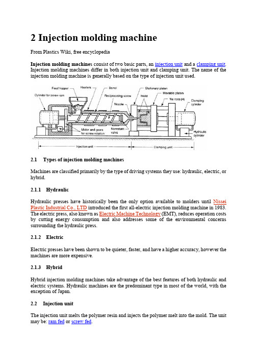
2 Injection molding machineFrom Plastics Wiki, free encyclopediaInjection molding machines consist of two basic parts, an injection unit and a clamping unit. Injection molding machines differ in both injection unit and clamping unit. The name of the injection molding machine is generally based on the type of injection unit used.2.1Types of injection molding machinesMachines are classified primarily by the type of driving systems they use: hydraulic, electric, or hybrid.2.1.1HydraulicHydraulic presses have historically been the only option available to molders until Nissei Plastic Industrial Co., LTD introduced the first all-electric injection molding machine in 1983. The electric press, also known as Electric Machine Technology (EMT), reduces operation costs by cutting energy consumption and also addresses some of the environmental concerns surrounding the hydraulic press.2.1.2ElectricElectric presses have been shown to be quieter, faster, and have a higher accuracy, however the machines are more expensive.2.1.3HybridHybrid injection molding machines take advantage of the best features of both hydraulic and electric systems. Hydraulic machines are the predominant type in most of the world, with the exception of Japan.2.2Injection unitThe injection unit melts the polymer resin and injects the polymer melt into the mold. The unit may be: ram fed or screw fed.The ram fed injection molding machine uses a hydraulically operated plunger to push the plastic through a heated region. The high viscosity melt is then spread into a thin layer by a "torpedo" to allow for better contact with the heated surfaces. The melt converges at a nozzle and is injected into the mold.Reciprocating screw A combination melting, softening, and injection unit in an injection molding machine. Another term for the injection screw. Reciprocating screws are capable of turning as they move back and forth.The reciprocating screw is used to compress, melt, and convey the material. The reciprocating screw consists of three zones (illustrated below):•feeding zone•compressing zone•metering zoneWhile the outside diameter of the screw remains constant, the depth of the flights on the reciprocating screw decreases from the feed zone to the beginning of the metering zone. These flights compress the material against the inside diameter of the barrel, which creates viscous (shear) heat. This shear heat is mainly responsible for melting the material. The heater bands outside the barrel help maintain the material in the molten state. Typically, a molding machine can have three or more heater bands or zones with different temperature settings.Injection molding reciprocating screw An extruder-type screw rotates within a cylinder, which is typically driven by a hydraulic drive mechanism. Plastic material is moved through the heated cylinder via the screw flights and the material becomes fluid. The injection nozzle is blocked by the previous shot, and this action causes the screw to pump itself backward through the cylinder. (During this step, material is plasticated and accumulated for the next shot.) When the mold clamp has locked, the injection phase takes place. At this time, the screw advances, acting as a ram. Simultaneously, the non-return valve closes off the escape passages in the screw and the screw serves as a solid plunger, moving the plastic ahead into the mold. When the injection stroke and holding cycle is completed, the screw is energized to return and the non-return valve opens, allowing plastic to flow forward from the cylinder again, thus repeating the cycle.2.2.1Feed hopperThe container holding a supply molding material to be fed to the screw. The hopper located over the barrel and the feed throat connects them.2.2.2Injection ramThe ram or screw that applies pressure on the molten plastic material to force it into the mold cavities.2.2.3Injection screwThe reciprocating-screw machine is the most common. This design uses the same barrel for melting and injection of plastic.The alternative unit involves the use of separate barrels for plasticizing and injecting the polymer. This type is called a screw-preplasticizer machine or two-stage machine. Plastic pellets are fed from a hopper into the first stage, which uses a screw to drive the polymer forward and melt it. This barrel feeds a second barrel, which uses a plunger to inject the melt into the mold. Older machines used one plunger-driven barrel to melt and inject the plastic. These machines are referred to as plunger-type injection molding machines.2.2.4BarrelBarrel is a major part that melts resins transmitted from hopper through screws and structured in a way that can heat up resins to the proper temperature. A band heater, which can control temper atures in five sections, is attached outside the barrel. Melted resins are supplied to the mold passing through barrel head, shot-off nozzle, and one-touch nozzle.2.2.5Injection cylinderHydraulic motor located inside bearing box, which is connected to injection cylinder load, rotates screw, and the melted resins are measures at the nose of screw. There are many types of injection cylinders that supply necessary power to inject resins according to the characteristics of resins and product types at appropriate speed and pressure. This model employs the double cylinder type. Injection cylinder is composed of cylinder body, piston, and piston load.2.3Clamping unitThe clamping unit holds the mold together, opens and closes it automatically, and ejects the finished part. The mechanism may be of several designs, either mechanical, hydraulic or hydromechanical.Toggle clamps - a type clamping unit include various designs. An actuator moves the crosshead forward, extending the toggle links to push the moving platen toward a closed position. At the beginning of the movement, mechanical advantage is low and speed is high; but near the end of the stroke, the reverse is true. Thus, toggle clamps provide both high speed and high force at different points in the cycle when they are desirable. They are actuated either by hydraulic cylinders or ball screws driven by electric motors. Toggle-clamp units seem most suited to relatively low-tonnage machines.Two clamping designs: (a) one possible toggle clamp design (1) open and (2) closed; and (b) hydraulic clamping (1) open and (2) closed. Tie rods used to guide movuing platens not shown.Hydraulic clamps are used on higher-tonnage injection molding machines, typically in the range 1300 to 8900 kN (150 to 1000 tons). These units are also more flexible than toggle clamps in terms of setting the tonnage at given positions during the stroke.Hydraulic Clamping System is using the direct hydraulic clamp of which the tolerance is still and below 1 %, of course, better than the toggle system. In addition, the Low Pressure Protection Device is higher than the toggle system for 10 times so that the protection for the precision and expensive mold is very good. The clamping force is focus on the central for evenly distribution that can make the adjustment of the mold flatness in automatically. Hydromechanical clamps -clamping units are designed for large tonnages, usually above 8900 kN (1000 tons); they operate by (1) using hydraulic cylinders to rapidly move the mold toward closing position, (2) locking the position by mechanical means, and (3) using high pressure hydraulic cylinders to finally close the mold and build tonnage.2.3.1Injection moldThere are two main types of injection molds: cold runner (two plate and three plate designs) and hot runner– the more common of the runnerless molds.2.3.2Injection platensSteel plates on a molding machine to which the mold is attached. Generally, two platens are used; one being stationary and the other moveable, actuated hydraulically to open and close the mold. It actually provide place to mount the mould. It contains threaded holes on which mould can be mounted using clamps.2.3.3Clamping cylinderA device that actuates the chuck through the aid of pneumatic or hydraulic energy.2.3.4Tie BarTie bars support clamping power, and 4 tie bars are located between the fixing platen and the support platen.3 Injection mouldFrom Wikipedia, the free encyclopediaMold A hollow form or cavity into which molten plastic is forced to give the shape of the required component. The term generally refers to the whole assembly of parts that make up the section of the molding equipment in which the parts are formed. Also called a tool or die. Moulds separate into at least two halves (called the core and the cavity) to permit the part to be extracted; in general the shape of a part must be such that it will not be locked into the mould. For example, sides of objects typically cannot be parallel with the direction of draw (the direction in which the core and cavity separate from each other). They are angled slightly; examination of most household objects made from plastic will show this aspect of design, known as draft. Parts that are "bucket-like" tend to shrink onto the core while cooling and, after the cavity is pulled away, are typically ejected using pins. Parts can be easily welded together after moulding to allow for a hollow part (like a water jug or doll's head) that couldn't physically be designed as one mould.More complex parts are formed using more complex moulds, which may require moveable sections, called slides, which are inserted into the mould to form particular features that cannot be formed using only a core and a cavity, but are then withdrawn to allow the part to be released. Some moulds even allow previously moulded parts to be re-inserted to allow a new plastic layer to form around the first part. This system can allow for production of fully tyred wheels.Traditionally, moulds have been very expensive to manufacture; therefore, they were usually only used in mass production where thousands of parts are being produced.Molds require: Engineering and design, special materials, machinery and highly skilled personnel to manufacture, assemble and test them.Cold-runner moldCold-runner mold Developed to provide for injection of thermoset material either directly into the cavity or through a small sub-runner and gate into the cavity. It may be compared to the hot-runner molds with the exception that the manifold section is cooled rather than heated to maintain softened but uncured material. The cavity and core plates are electrically heated to normal molding temperature and insulated from the cooler manifold section.3.1.1Types of Cold Runner MoldsThere are two major types of cold runner molds: two plate and three plate.3.1.2Two plate moldA two plate cold runner mold is the simplest type of mold. It is called a two plate mold because there is one parting plane, and the mold splits into two halves. The runner system must be located on this parting plane; thus the part can only be gated on its perimeter.3.1.3Three plate moldA three plate mold differs from a two plate in that it has two parting planes, and the mold splits into three sections every time the part is ejected. Since the mold has two parting planes, the runner system can be located on one, and the part on the other. Three plate molds are used because of their flexibility in gating location. A part can be gated virtually anywhere along its surface.3.1.4AdvantagesThe mold design is very simple, and much cheaper than a hot runner system. The mold requires less maintenance and less skill to set up and operate. Color changes are also very easy, since all of the plastic in the mold is ejected with each cycle.3.1.5DisadvantagesThe obvious disadvantage of this system is the waste plastic generated. The runners are either disposed of, or reground and reprocessed with the original material. This adds a step in the manufacturing process. Also, regrind will increase variation in the injection molding process, and could decrease the plastic's mechanical properties.3.1.6Hot runner moldHot-runner mold -injection mold in which the runners are kept hot and insulated from the chilled cavities. Plastic freezeoff occurs at gate of cavity; runners are in a separate plate so they are not, as is the case usually, ejected with the piece.Hot runner molds are two plate molds with a heated runner system inside one half of the mold.A hot runner system is divided into two parts: the manifold and the drops. The manifold has channels that convey the plastic on a single plane, parallel to the parting line, to a point abovethe cavity. The drops, situated perpendicular to the manifold, convey the plastic from the manifold to the part.3.1.7Types of Hot Runner MoldsThere are many variations of hot runner systems. Generally, hot runner systems are designated by how the plastic is heated. There are internally and externally heated drops and manifolds.3.1.8Externally heated hot runnersExternally heated hot runner channels have the lowest pressure drop of any runner system (because there is no heater obstructing flow and all the plastic is molten), and they are better for color changes none of the plastic in the runner system freezes. There are no places for material to hang up and degrade, so externally heated systems are good for thermally sensitive materials.3.1.9Internally heated hot runnersInternally heated runner systems require higher molding pressures, and color changes are very difficult. There are many places for material to hang up and degrade, so thermally sensitive materials should not be used. Internally heated drops offer better gate tip control. Internally heated systems also better separate runner heat from the mold because an insulating frozen layer is formed against the steel wall on the inside of the flow channels.3.1.10 insulated hot runnersA special type of hot runner system is an insulated runner. An insulated runner is not heated; the runner channels are extremely thick and stay molten during constant cycling. This system is very inexpensive, and offers the flexible gating advantages of other hot runners and the elimination of gates without the added cost of the manifold and drops of a heated hot runner system. Color changes are very easy. Unfortunately, these runner systems offer no control, and only commodity plastics like PP and PE can be used. If the mold stops cycling for some reason, the runner system will freeze and the mold has to be split to remove it. Insulated runners are usually used to make low tolerance parts like cups and frisbees.3.1.11 DisadvantagesHot-runner mold is much more expensive than a cold runner, it requires costly maintenance, and requires more skill to operate. Color changes with hot runner molds can be difficult, since it is virtually impossible to remove all of the plastic from an internal runner system.3.1.12 AdvantagesThey can completely eliminate runner scrap, so there are no runners to sort from the parts, and no runners to throw away or regrind and remix into the original material. Hot runners are popular in high production parts, especially with a lot of cavities.Advantages Hot Runner System Over a Cold Runner System include:•no runners to disconnect from the molded parts•no runners to remove or regrind, thus no need for process/ robotics to remove them•having no runners reduces the possibility of contamination•lower injection pressures•lower clamping pressure•consistent heat at processing temperature within the cavity•cooling time is actually shorter (as there is no need for thicker, longer-cycle runners)•shot size is reduced by runner weight•cleaner molding process (no regrinding necessary)•nozzle freeze and sprue sticking issues eliminated中文翻译注塑模具设计与制造2 注射机选自《维基百科》注射机由两个基本部分组成,注射装置和夹紧装置。
- 1、下载文档前请自行甄别文档内容的完整性,平台不提供额外的编辑、内容补充、找答案等附加服务。
- 2、"仅部分预览"的文档,不可在线预览部分如存在完整性等问题,可反馈申请退款(可完整预览的文档不适用该条件!)。
- 3、如文档侵犯您的权益,请联系客服反馈,我们会尽快为您处理(人工客服工作时间:9:00-18:30)。
模具设计与制造模具是制造业的重要工艺基础,在我国,模具制造属于专用设备制造业。
中国虽然很早就开始制造模具和使用模具,但长期未形成产业。
直到 20 世纪 80年代后期,中国模具工业才驶入发展的快车道。
近年,不仅国有模具企业有了很大发展,三资企业、乡镇(个体)模具企业的发展也相当迅速。
虽然中国模具工业发展迅速,但与需求相比,显然供不应求,其主要缺口集中于精密、大型、复杂、长寿命模具领域。
由于在模具精度、寿命、制造周期及生产能力等方面,中国与国际平均水平和发达国家仍有力,今后更要着重于行业内部结构的调整和技术发展水平的提高。
结构调整方面较大差距,因此,每年需要大量进口模具。
中国模具产业除了要继续提高生产能,主要是企业结构向专业化调整,产品结构向着中高档模具发展,向进出口结构的改进,中高档汽车覆盖件模具成形分析及结构改进、多功能复合模具和复合加工及激光技术在模具设计制造上的应用、高速切削、超精加工及抛光技术、信息化方向发展。
近年,模具行业结构调整和体制改革步伐加大,主要表现在,大型、精密、复杂、长寿命、中高档模具及模具标准件发展速度高于一般模具产品;塑料模和压铸模比例增大;专业模具厂数量及其生产能力增加;“三资”及私营企业发展迅速;股份制改造步伐加快等。
从地区分布来看,以珠江三角洲和长江三角洲为中心的东南沿海地区发展快于中西部地区,南方的发展快于北方。
目前发展最快、模具生产最为集中的省份是广东和浙江,江苏、上海、安徽和山东等地近几年也有较大发展。
虽然我国模具总量目前已达到相当规模,模具水平也有很大提高,但设计制造水平总体上落后于德、美、日、法、意等工业发达国家许多。
当前存在的问题和差距主要表现在以下几方面:(1)总量供不应求国内模具自配率只有 70左右。
其中低档模具供过于求,中高档模具自配率只有 50左右。
(2)企业组织结构、产品结构、技术结构和进出口结构均不合理我国模具生产厂中多数是自产自配的工模具车间(分厂),自产自配比例高达 60左右,而国外模具超过 70属商品模具。
专业模具厂大多是“大而全”、“小而全”的组织形式,而国外大多是“小而专”、“小而精”。
国内大型、精密、复杂、长寿命的模具占总量比例不足 30,而国外在 50以上。
2004 年,模具进出口之比为 3.7:1,进出口相抵后的净进口额达 13.2 亿美元,为世界模具净进口量最大的国家。
(3)模具产品水平大大低于国际水平,生产周期却高于国际水平产品水平低主要表现在模具的精度、型腔表面粗糙度、寿命及结构等方面。
(4)开发能力较差,经济效益欠佳我国模具企业技术人员比例低,水平较低,且不重视产品开发,在市场中经常处于被动地位。
我国每个模具职工平均年创造产值约合 1 万美元,国外模具工业发达国家大多是 15~20 万美元,有的高达25~30 万美元,与之相对的是我国相当一部分模具企业还沿用过去作坊式管理,真正实现现代化企业管理的企业较少。
造成上述差距的原因很多,除了历史上模具作为产品长期未得到应有的重视,以及多数国有企业机制不能适应市场经济之外,还有下列几个原因:(1)国家对模具工业的政策支持力度还不够虽然国家已经明确颁布了模具行业的产业政策,但配套政策少,执行力度弱。
目前享受模具产品增值税的企业全国只有 185 家,大多数企业仍旧税负过重。
模具企业进行技术改造引进设备要缴纳相当数量的税金,影响技术进步,而且民营企业贷款十分困难。
(2)人才严重不足,科研开发及技术攻关投入太少模具行业是技术、资金、劳动密集的产业,随着时代的进步和技术的发展,掌握并且熟练运用新技术的人才异常短缺,高级模具钳工及企业管理人才也非常紧张。
由于模具企业效益欠佳及对科研开发和技术攻关重视不够,科研单位和大专院校的眼睛盯着创收,导致模具行业在科研开发和技术攻关方面投入太少,致使模具技术发展步伐不大,进展不快。
(3)工艺装备水平低,且配套性不好,利用率低近年来我国机床行业进步较快,已能提供比较成套的高精度加工设备,但与国外装备相比,仍有较大差距。
虽然国内许多企业已引进许多国外先进设备,但总体的装备水平比国外许多企业低很多。
由于体制和资金等方面的原因,引进设备不配套,设备与附件不配套现象十分普遍,设备利用率低的问题长期得不到较妥善的解决。
(4)专业化、标准化、商品化程度低,协作能力差由于长期以来受“大而全”“小而全”影响,模具专业化水平低,专业分工不细致,商品化程度低。
目前国内每年生产的模具,商品模具只占 40左右,其余为自产自用。
模具企业之间协作不畅,难以完成较大规模的模具成套任务。
模具标准化水平低,模具标准件使用覆盖率低也对模具质量、成本有较大影响,特别是对模具制造周期有很大影响。
(5)模具材料及模具相关技术落后模具材料性能、质量和品种问题往往会影响模具质量、寿命及成本,国产模具钢与国外进口钢材相比有较大差距。
塑料、板材、设备性能差,也直接影响模具水平的提高。
目前,我国经济仍处于高速发展阶段,国际上经济全球化发展趋势日趋明显,这为我国模具工业高速发展提供了良好的条件和机遇。
一方面,国内模具市场将继续高速发展,另一方面,模具制造也逐渐向我国转移以及跨国集团到我国进行模具采购趋向也十分明显。
因此,放眼未来,国际、国内的模具市场总体发展趋势前景看好,预计中国模具将在良好的市场环境下得到高速发展,我国不但会成为模具大国,而且一定逐步向模具制造强国的行列迈进。
“十一五”期间,中国模具工业水平不仅在量和质的方面有很大提高,而且行业结构、产品水平、开发创新能力、企业的体制与机制以及技术进步的方面也会取得较大发展。
模具技术集合了机械、电子、化学、光学、材料、计算机、精密监测和信息网络等诸多学科,是一个综合性多学科的系统工程。
模具技术的发展趋势主要是模具产品向着更大型、更精密、更复杂及更经济的方向发展,模具产品的技术含量不断提高,模具制造周期不断缩短,模具生产朝着信息化、无图化、精细化、自动化的方向发展,模具企业向着技术集成化、设备精良化、产批品牌化、管理信息化、经营国际化的方向发展。
我国模具行业今后仍需提高的共性技术有:(1)建立在 CAD/CAE 平台上的先进模具设计技术,提高模具设计的现代化、信息化、智能化、标准化水平。
(2)建立在 CAM/CAPP 基础上的先进模具加工技术与先进制造技术相结合,提高模具加工的自动化水平与生产效率。
(3)模具生产企业的信息化管理技术。
例如 PDM(产品数据管理)、ERP(企业资源管理)、MIS(模具制造管理信息系统)及 INTERMET 平台等信息网络技术的应用、推广及发展。
(4)高速、高精、复合模具加工技术的研究与应用。
例如超精冲压模具制造技术、精密塑料和压铸模具制造技术等。
(5)提高模具生产效率、降低成本和缩短模具生产周期的各种快速经济模具制造技术。
(6)先进制造技术的应用。
例如热流道技术、气辅技术、虚拟技术、纳米技术、高速扫描技术、逆向工程、并行工程等技术在模具研究、开发、加工过程中的应用(7)原材料在模具中成形的仿真技术。
(8)先进的模具加工和专有设备的研究与开发。
(9)模具及模具标准件、重要辅件的标准化技术。
(10)模具及其制品的检测技术。
(11)优质、新型模具材料的研究与开发及其正确应用。
(12)模具生产企业的现代化管理技术。
模具行业在“十一五”期间需要解决的重点关键技术应是模具信息化、数字化技术和精密、超精、高速、高效制造技术方面的突破。
随着国民经济总量和工业产品技术的不断发展,各行各业对模具的需求量越来越大,技术要求也越来越高。
虽然模具种类繁多,但其发展重点应该是既能满足大量需要,又有较高技术含量,特别是目前国内尚不能自给,需大量进口的模具和能代表发展方向的大型、精密、复杂、长寿命模具。
模具标准件的种类、数量、水平、生产集中度等对整个模具行业的发展有重大影响。
因此,一些重要的模具标准件也必须重点发展,而且其发展速度应快于模具的发展速度,这样才能不断提高我国模具标准化水平,从而提高模具质量,缩短模具生产周期,降低成本。
由于我国的模具产品在国际市场上占有较大的价格优势,因此对于出口前景好的模具产品也应作为重点来发展。
根据上述需要量大、技术含量高、代表发展方向、出口前景好的原则选择重点发展产品,而且所选产品必须目前已有一定技术基础,属于有条件、有可能发展起来的产品。
根据“十一五”模具行业发展规划,“十一五”期间模具产品发展重点主要有如下几类:(1)汽车覆盖件模具冲压模具占模具总量的 40以上。
汽车覆盖件模具主要为汽车配套,也包括为农用车、工程机械和农机配套的覆盖件模具,它在冲压模具中具有很大的代表性,模具大都是大中型,结构复杂,技术要求高。
尤其是为轿车配套的覆盖件模具,要求更高,可以代表冲压模具的水平。
此类模具我国已有一定的技术基础,已为中档轿车配套,但水平还不高,能力不足,目前满足率只有一半左右。
中高档轿车覆盖件模具主要依靠进口,已成为汽车发展的瓶颈,极大的影响着车型开发。
(2)精密冲压模具多工位级进模和精冲模代表了冲压模具的发展方向,精度要求寿命要求极高,主要为电子工业、汽车、仪器仪表、电机电器等配套。
这两种模具,国内已有相当基础,并已引进了国外技术及设备,个别企业生产的产品已达到世界水平,但大部分企业仍有较大差距,供应总量不足,进口很多。
(3)大型精密塑料模具塑料模具占模具总量近 40,而且这个比例还在上升。
塑料模具中为汽车和家电配套的大型注塑模具,为集成电路配套的塑封模,为电子信息产业和机械及包装配套的多层、多腔、多材质、多色精密注塑模,为新型建材及节水农业配套的塑料异型材挤出模及管路和喷头模具等,目前虽然已有相当技术基础并正在快速发展,但技术水平与国外仍有较大差距,总量供不应求,每年的进口额达几亿美元。
(4)主要模具标准件目前国内已有较大产量的模具标准件主要是模架、导向件、推杆推管、弹性元件等。
这些产品不但国内配套大量需要,出口前景也很好,应继续大力发展。
氮气缸和热流道元件主要依靠进口,应在现有基础上提高水平,形成标准并组织规模化生产。
(5)其他高技术含量的模具占模具总量给 8的压铸模具中,大型薄壁精密压铸技术含量高,难度大。
镁合金压铸模具目前虽然刚起步,但发展前景好,有代表性。
子午线橡胶轮胎模具也是发展方向,其中活络模技术难度最大。
与快速成型技术相结合的一些快速制模技术及相应的快速经济模具具有很好的发展前景。
这些高技术含量的模具在“十一五”期间也应重点发展。
Mold design and manufactureThe mold is the manufacturing industry important craft foundation in ourcountry the mold manufacture belongs to the special purpose equipmentmanufacturing industry. China although very already starts to make the mold and theuse mold but long-term has not formed the industry. Straight stabs 0 centuries 80slater periods the Chinese mold industry only then drives into the developmentspeedway. Recent years not only the state-owned mold enterprise had the very bigdevelopment the three investments enterprise the villages and towns individual themold enterprises development also quite rapid . Although the Chinese mold industrial development rapid but compares with thedemand obviously falls short of demand its main gap concentrates precisely tolarge-scale is complex the long life mold domain. As a result of in aspect and so onmold precision life manufacture cycle and productivity China and the internationalaverage horizontal and the developed country still had a bigger disparity thereforeneeded massively to import the mold every year . The Chinese mold industry except must continue to sharpen the productivityfrom now on will have emphatically to the profession internal structure adjustmentand the state-of-art enhancement. The structure adjustment aspect mainly is theenterprise structure to the specialized adjustment the product structure to center theupscale mold development to the import and export structure improvement centerthe upscale automobile cover mold forming analysis and the structure improvementthe multi-purpose compound mold and the compound processing and the lasertechnology in the mold design manufacture application the high-speed cutting thesuperfinishing and polished the technology the information direction develops . The recent years the mold profession structure adjustment and the organizationalreform step enlarges mainly displayed in large-scale precise was complex the longlife center the upscale mold and the mold standard letter development speed is higherthan the common mold product The plastic mold and the compression casting moldproportion increases Specialized mold factory quantity and its productivity increasequotThe three investmentsquot and the private enterprise develops rapidly The joint stocksystem transformation step speeds up and so on. Distributes from the area lookedtake Zhujiang Delta and Yangtze River delta as central southeast coastal areadevelopment quickly to mid-west area south development quicklyto north. Atpresent develops quickest the mold produces the most centralized province isGuangdong and Zhejiang places such as Jiangsu Shanghai Anhui and Shandong alsohas a bigger development in recent years . Although our country mold total quantity had at present achieved the suitablescale the mold level also has the very big enhancement after but design manufacturehorizontal overall rise and fall industry developed country and so on Yu De Americadate France Italy many. The current existence question and the disparity mainlydisplay in following several aspects: 1 The total quantity falls short of demand Domestic mold assembling oneself rate only about 70. Low-grade mold center upscale mold assembling oneself rate only has 50 about . 2 The enterprise organizational structure the product structure the technicalstructure and the import and export structure does not gather Iin our country mold production factory to be most is from the labor moldworkshop which produces assembles oneself branch factory from producesassembles oneself the proportion to reach as high as about 60 but the overseas moldultra 70 is the commodity mold. The specialized mold factory mostly is quotlarge andcompletequot quotsmall and entirequot organization form but overseas mostly is quotsmall butquotquotis specially small and finequot. Domestic large-scale precise complex the long lifemold accounts for the total quantity proportion to be insufficient 30 but overseas in50 above 2004 years ratio of the mold import and export is 3.7:1 the import andexport balances the after net import volume to amount to 1.32 billion US dollars isworld mold net import quantity biggest country . 3 The mold product level greatly is lower than the international standard The production cycle actually is higher than the international water broadproduct level low mainly to display in the mold precision cavity aspect and so onsurface roughness life and structure .4 Develops the ability badly economic efficiency unsatisfactory our countrymold enterprise technical personnel proportion low The level is lower also does not take the product development frequently is inthe passive position in the market. Our country each mold staff average year creationoutput value approximately ten thousand US dollars overseas mold industrydeveloped country mostly 15 to10000 US dollars some reach as high as 25 to10000US dollars relative is our country quite part of molds enterprises also continues to usethe workshop type management with it truly realizes the enterprise which themodernized enterprise manages few To create the above disparity the reason to be very many the mold long-term hasnot obtained the value besides the history in as the product which shouldhave as wellas the most state-owned enterprises mechanism cannot adapt the market economy butalso has the following several reasons: . 1 Country to mold industry policy support dynamics also insufficiently Although the country already was clear about has promulgated the moldprofession industrial policy but necessary policy few carried out dynamics to beweak. At present enjoyed the mold product increment duty enterprise nation 185 themajority enterprise still the tax burden is only overweight. The mold enterprise carrieson the technological transformations introduction equipment to have to pay theconsiderable amount the tax money affects the technology advancement moreoverprivately operated enterprise loan extremely difficult . 2 Talented person serious insufficient the scientific research development andthe technical attack investment too urine Mold profession is the technology the fund the work crowded industry alongwith the time progress and the technical development grasps the talented personwhich and skilled utilizes the new technology exceptionally short the high-qualitymold fitter and the enterprise management talent extremely is also anxious. Becausethe mold enterprise benefit unsatisfactory and takes insufficiently the scientificresearch development and the technical attack the scientific research unit and theuniversities colleges and institutes eye stares at is creating income causes the moldprofession invests too few in the scientific research development and the technicalattack aspect causes the mold technological development step not to be bigprogresses not quick . 3 The craft equipment level to be low also necessary is not good the use factorlow recent years our country engine bed profession progressed quickly has been ableto provide the quite complete precision work equipment but compared with theoverseas equipment still had a bigger disparity. Although the domestic manyenterprises have introduced many overseas advanced equipment but the overallequipment level low are very more than the overseas many enterprises. As a result ofaspect the and so on system and fund reason introduces the equipment not notnecessary the equipment and the appendix not necessary phenomenon are extremelycommon the equipment utilization rate low question cannot obtain the comparativelyproperly solu.。