ASME中国制造-常压储罐计算
ASME中国制造-中英文计算书-永业

用途
Spec
标准号
N1
80
6
Inlet进气口
ASME B16.5
N2
80
6
Outlet出气口
ASME B16.5
N3
80
6
DRAIN疏水口
ASME B16.5
Design formula forpipe:接管计算公式
Appendix附录1 1-1(a)(1)
Design formula for cylindrical shell :圆柱形壳体计算公式
ProductNo.产品编号:A2012001
Doc. No.:文件号:DCS-1201
1
REVISION
0
First issue
REV.
DESCRIPTION
PREPARED BY
REVIEWED BY
APPROVED BY
CONTENT
Cover封面1
Content目录2
1.Designparameters and the condition设计参数和条件3
注:摘自ASME第Ⅱ卷D篇2010版及2011增补,表1A。
3.Strength Calculations强度计算
3.1Calculationof shell wall thickness壳体壁厚计算
checking condition校核条件:UG-27 ( c )( 1 )
t=8mm< R/2 =300/2=150mm
Design formula:设计公式
ts/L=7.2/0.9D=7.2/0.9×600=0.015>0.002 (ts=7.2mm)
UG-32(d)(1)
ASME取证用储罐强度计算书汇总

设计计算书Design Calculation Sheet1. 设计参数和条件Design Data and Condition:1) 设计所遵循的规范Applicable Design Code:ASME SectionⅧ,Div.1, 20132) 设计压力(p) : 内部1.3MpaDesign Pressure (p): Internal 1.3 MPa3) 设计温度: 60℃Design Temperature: 60℃4) 焊接接头系数(E): 壳体为0.85,封头为0.85(无缝)Joint Efficiency (E): 0.85 for Shell and 0.85 for Heads(seamless)5) 材料最大许用应力Material Max. Allowable Stress:Based on ASME Code Sec.Ⅱ, Part D Table 1A壳体和封头: SA516 Gr. 485,60℃时为138MPaShell & Heads: SA516 Gr. 485 Material Max. Allowable Stress is 138MPa at 60℃;接管: SA105M钢,60℃时为138MPaNozzles:SA105M Steel Material Max. Allowable Stress 138 MPa at 60℃;6) 媒介: 空气Medium: Air (Non lethal)7) 封头类型: 2:1椭圆封头Head type: 2:1Ellipsoidal Head;8) 其他载荷: 依据“客户设计说明书”(Doc. No. TS-15-01 Rev.0)Others Loadings: As Shown in“Customer’s Design Specification”(Doc. No. TS-15-01 Rev. 0)9) 腐蚀余度:2.0 mmCorrosion Allowance: 2.0 mm10) 容器外形和尺寸:依据“客户设计说明书”(Doc. No. TS-15-01 Rev.0)Layout of Vessel and Dimension:As Shown in“Customer’s Design Specification”(Doc. No. TS-15-01 Rev. 0) 11) 钢印要求: 要求ASME标识Stamp required: ASME Certification Mark required12) NB要求: 不要求NB钢印NB stamp required: NO “NB” stamp required.Verify for UG-22 LoadingPressure符号 Symbols:t= 壳体要求最小厚度,mmt = minimum required thickness of shell, mm P = 内部设计压力, 1.3MPaP = internal design pressure, 1.3 MPa [see UG-21] R = 预计容器筒内半径, 250mmR = inside radius of the shell course under consideration, 250mm S = 最大许用应力值,138MPaS = maximum allowable stress value, 138MPa [ see ASME Code Part II DTable 1A for material SA-516 Gr.485] E = 焊接接头系数,0.85E = joint efficiency, 0.85 [see Table UW-12(1)]Since P=1.3MPa is less than 0.385SE=45.16MPa, Formula UG-27(c)(1) is used:)(2.811.36.085.0381)2025(3.16.0mm P SE PR t =⨯-⨯+⨯=-=考虑腐蚀裕量:Consider of corrosion allowable: tr= t + Ca = 2.81 + 2.0 = 4.81mmThese formulas will govern only when the circumferential joint efficiency is less than one-half the longitudinal joint efficiency, according to UG-27(c) (2) note 20, the formula UG-27(c) (2) for longitudinal stress needn’t considered. 公称钢板规则厚度=10mmNominal Plate Thickness Ordered = 10 mm钢板厚度可允许下偏差=0.25mm[see UG-16(c)] Plate Under tolerance=0.25 mm [ see UG-16(c)]UG-16 (b)(4) the minimum thickness of pressure retaining components >2.5mm for air service(exclusive any corrosion allowance). 实际使用厚度=10-0.25=9.75> 4.81mm ,并且也>2.5+2mm,可以。
压缩空气储罐计算书-ASMEU钢印

CALCULATION SHEET FOR COMPRESSED AIR STORAGE TANK(JOB NO.: SP09-U-001)(DRAWING NO.: SP09-001-1. REV. 1)SUZHOU PFAUDLER GLASS-LINED EQUIPMENT CO., LTD苏州法德尔搪玻璃设备有限公司.TABLE OF CONTENTS1. DESIGN DATA:(1) APPLICABLE CODECUSTOMER SPECIFICA TIONASME SEC.ⅧDIV. 1 2007EDITION AND2009 ADDENDA.DOC. NO. DC-09-1/Rev 0(2) DESIGN PRESSURE INTERNAL 1.3MPa(3) DESIGN TEMPERA TURE 50℃(4) TYPE OF JOINTS OF CA TEGORIES A AND B TYPE NO.1(5) RADIOGRAPHY SPOT per UW-11(b)(6) JOINT EFFICIENCY SHELL: 0.85, HEAD: 0.85, SHEEL to HEAD: 0.85(7) CORROSION ALLOWANCE 1 mm.(8) MA TERIAL SHELL & HEAD :SA-516M Gr.485NOZZLE: SA-106Gr.BFLANGE: SA-105MSUPPORT LEGS:20(GB/T8163-2008)SUPPORT PLA TE: SA-285M Gr.CLUG:SA-516M Gr.485(9) MAX. ALLOWABLE STRESS A T DESIGNTEMPERA TURE SA-285M Gr.C:108MPa at 50℃SA-105M: 138MPa at 50℃SA-106Gr.B: 118MPa at 50℃SA-516M Gr.485: 138MPa at 50℃(10) HEAD TYPE 2:1 Standard Ellipsoidal Head(11) TANK CAPACITY 1.5 m3(12) SERVICE FLUID COMPRESSED AIR (no lethal)(13) MIN. SERVICE TEMPERA TURE -10℃(14) THE LOADING CONSIDERED IN DESIGNING SEE TABLE 1-1(15) TANK DIMENSIONS SEE FIG. 1-1TABLE 1-1 LOADING CONSIDERED IN DESIGNINGItem Description Yes No1 Internal pressure [ √ ] [ ]2 External pressure [ ] [ √ ]3 Weight of vessel [ √ ] [ ]4 Weight of normal contents under operation conditions [ ] [√ ]5 Weight of normal contents under test conditions [ √ ] [ ]6 Superimposed static reactions from weight of attached equipment [ ] [ √ ]7 The attachments of internals[ ] [ √ ]8 The attachments of vessel supports (skirt, legs, saddles etc.) [ √ ] [ ]9 The attachments of lifting lugs [ √ ] [ ]10 Cyclic and dynamic reactions due to pressure [ ] [ √ ]11 Cyclic and dynamic reactions due to thermal variations [ ] [ √ ]12 Cyclic and dynamic reactions due to equipment mounted on the vessel [ ] [ √ ]13 Cyclic and dynamic reactions due to mechanical loadings [ ] [ √ ]14 Wind reactions [ ] [ √ ]15 Snow reactions [ ] [ √ ]16 Seismic reactions [ ] [ √ ]17 Impact reactions, such as those due to fluid shock [ ] [ √ ]18 Temperature gradients [ ] [ √ ]19 Differential thermal expansion [ ] [ √ ]20 Abnormal pressure, such as those caused by deflagration [ ] [ √ ]21 Test pressure and coincident static head acting during the test[√ ] [ ] (See UG-99)LIST OF NOZZLESFIG.1-1 Brief Drawing of Shell2. THICKNESS OF CYLINDRICAL SHELL UNDER INTERNAL PRESSUREASME SEC.Ⅷ DIV.1 UG-27 ● Part: Shell ● Design pressure P (MPa) : 1.3 ● Design temperature (℃):50● Material: SA-516M Gr.485● Maximum allowable stress value at design temperature S d (MPa) : 138 ● Maximum allowable stress value at test temperature S t (MPa) : 138 ● Height to point under considerationH (m) : 1.900 ● Density of test medium (water) at test temperature ρ (kg/m 3) : 1000 ● Type of welded joints in TABLE UW-12 : Type No. (1)● Radiographic examination:SPOT Per UW-11(b)● Joint efficiency (specified in UW-12) E : 0.85 ● Corrosion allowance (designated by customer) C (mm) : 1.0 ● N ominal shell thickness tn (mm) 10 ● Inside radius corroded R (mm) : 501 ● Final center line radiusR f (mm) : 505● Original center line radius (specified in UCS-79) R o (mm):∞(Infinity )(1) Required minimum shell thickness excluding allowance (circumferential stress)0.385SE = 0.385×138×0.85=45.16> P according to UG-27(b)&(c) (a) For design conditionmm P E S PR t d 59.53.16.085.01385013.16.01min =⨯-⨯⨯=-=(b) For hydrostatic test conditionmmH E S R H P E S PR t t t 67.508.059.5)10/1000900.181.9(6.085.013850110/1000900.181.93.16.085.01385013.1)10/81.9(6.0)10/81.9(6.066662min =+=⨯⨯⨯-⨯⨯⨯⨯+⨯-⨯⨯=-+-=ρρ (2) Design thicknessRequired minimum shell thickness including allowance t=max(t min1,t min2)+C=5.67+1.0=6.67 mm (3) Provided thicknessNominal thickness (mm) 10 > t OK(4) Check minimum required thickness for paragraph UG-16 (b) (4)Minimum thickness required (including corrosion allowance) : 2.5+1=3.5mm, nominal thickness is 10mm>3.5mm, OK(5) Check extreme fiber elongation for paragraph UCS-79Maximum allowable fiber elongation without post weld heat treatment is based on the following formula: For single curvature%5%99.0%50515051050%1500<=⎪⎭⎫⎝⎛∞-⨯⨯=⎪⎪⎭⎫ ⎝⎛-=R R R t r ff None of the conditions in UCS-79 (1~5) apply, so no heat treatment after cold forming need to apply.3.THICKNESS OF ELLIPSOIDAL HEAD, PRESSURE ON CONCA VE SIDEASME SEC.ⅧDIV.1 UG-32●Part : heads●Design pressure P (MPa) : 1.3●Design temperature (℃) : 50●Material : SA-516M Gr.485 ●Maximum allowable stress value at design temperature S d(MPa) : 138●Maximum allowable stress value at test temperature S t(MPa) : 138●Height to point under consideration (bottom head) H (m) : 2.190●Height to point under consideration (top head) H (m) : 0.400●Density of test medium at test temperature ρ(kg/m3) : 1000●Type of welded joints in TABLE UW-12 : Seamless●Radiographic examination (A) : N.A●Weld joining heads to shell : Type No. (1),SPOT Per UW-11(b)●Joint efficiency (specified in UW-12(d)) E : 0.85●Corrosion allowance (designated by customer) C (mm) : 1●Inside diameter of ellipsoidal head (corroded) D 1002●Inside spherical radius of hemispherical head L (mm) : 501R f (mm) : 905●Crown final centerline radius (specified in UG-32(d)and UCS-79)r f (mm): 174.25●Knuckle final centerline radius (specified in UG-32(d)and UCS-79)●Original center line radius (specified in UCS-79) R0 (mm): ∞(Infinity)(1) Required minimum head thicknessWithout joint, according to UW-12(d), E=0.85,L=0.9D=0.9×1002=901.8mm t s /L = 8.5/901.8=0.0094> 0.002 according to UG-32(d) (a) For the top head according to UG-32(d)(a-1) for design conditionRequired minimum head thickness excluding allowance t minmm P E S PD t d 56.53.12.085.0138210023.12.021min =⨯-⨯⨯⨯=-=(b) For the bottom head(b-1) for design conditionRequired minimum head thickness excluding allowance tminmm P E S PD t d 56.53.12.085.0138210023.12.022min =⨯-⨯⨯⨯=-=(b-2) for hydrostatic test condition(Due to same dimension for ellipsoidal heads, the bottom head will be applied forcalculation)mmH E S D H P E S PD t t t 65.509.056.5)10/1000190.281.9(2.085.01382100210/1000190.281.93.12.085.0138210023.1)10/81.9(2.02)10/81.9(2.0266663min =+=⨯⨯⨯-⨯⨯⨯⨯⨯+⨯-⨯⨯⨯=-+-=ρρ (2) Design thicknessRequired minimum head thickness including allowance t=max(t min1,t min2,t min3)+C=5.65+1.0=6.65 mm(3) Provided thicknessNominal thickness (mm) 10Minimum thickness after forming (mm) 8.5 ≥ t OK(4) Check minimum head thickness for hemispherical head from paragraph UG-32 (b) & (f)0.665SE = 0.665 × 138× 1=91.77 MPa >PRequired minimum hemispherical head thicknessmm P SE PL t h 36.23.12.0113825013.12.02min =⨯-⨯⨯⨯=-=tr=t minh /E=2.36/0.85=2.78 mm < 8.5 mm OK(5) Check minimum required thickness for paragraph UG-16(b)(4)Minimum thickness required (including corrosion allowance) : 2.5+1= 3.5mm,minimum thickness after forming is 8.5mm.>3.5mm OK (6) Check extreme fiber elongation for paragraph UCS-79Maximum allowable fiber elongation without heat treatment is based on the following formula: For double curvature Crown radius elongation%5%83.0%90519051075%1750<=⎪⎭⎫⎝⎛∞-⨯⨯=⎪⎪⎭⎫ ⎝⎛-=R R R t r ff Knuckle radius elongation%5%3.4%25.174125.1741075%1750<=⎪⎭⎫⎝⎛∞-⨯⨯=⎪⎪⎭⎫ ⎝⎛-=R r r t r f f None of the conditions listed in UCS-79(d)(1) through (5) exist, so no heat treatment of heads after cold forming need to apply for SA-516M Gr.485 (P-NO.1 Group NO.2).4. THICKNESS OF NOZZLE NECK INTERNAL PRESSURE 4-1 FOR NOZZLE aASME SEC.Ⅷ DIV .1 UG-45●Design pressure P (MPa) : 1.3 ●Design temperature T (℃) : 50●Material of nozzle neck: SA-106Gr.B ●Allowablestress of nozzle neck material at design temperatureS d (MPa):118 ●Allowablestress of nozzle neck material at test temperatureS t (MPa):118●Material of shell: SA-516M Gr.485 ●Allowable stress of shell (or head) at design temperatureS s (MPa):138 ●Height to point under considerationH (m) : 1.580 ●Density of test medium at test temperature (water) ρ(kg/m 3) : 1000 ●Typeof welded joints of nozzle neck in TABLEUW-12:Seamless●Joint efficiency of nozzle neckE : 1.0 ●Corrosion allowance (designated by customer) C (mm) : 1 ●Outside radius of nozzle neckR o (mm) : 30.15 ●Nominal thickness of the standard wall pipe(B36.10M ) t std (mm) : 3.91 ●Inside radius of shell corrodedR s (mm): 501(1) Minimum required thickness of nozzle neck for par. UG-45 (a)0.385SE = 0.385× 118 ×1.00 = 45.43 > P (a) under design condition A ppendix 1-1 Required minimum thickness including allowancemm C P E S PR t d o 33.113.14.0111815.303.14.01min =+⨯+⨯⨯=++=(b)under hydrostatic test conditionRequired minimum thickness including allowancemmC H E S R H P E S PR t t ot o 334.11004.033.01)10/1000580.181.9(4.0111815.3010/1000580.181.93.14.0111815.303.1)10/81.9(4.0)10/81.9(4.066662min =++=+⨯⨯⨯+⨯⨯⨯⨯+⨯+⨯⨯=++++=ρρ(2) Minimum required thickness of shell for par. UG-45 (b) (1),and UG-16 (b) (4), Es = 1.00mm3.512.575.5175.413.16.011385013.16.0=+>=+=+⨯-⨯⨯=+-=mm C P E S PR t s s s s(3) Minimum thickness of standard wall pipe including allowance for par. UG-45 (b) (4)t p = 0.875t std + C = 0.875 × 3.91 + 1 =4.42mm t = (the smaller value of t s or t p ) per UG-45(b) = 4.42mm. > t min1,t min2(4) Provided thicknessNominal thickness (mm) 5.54Minimum thickness (mm) 5.54×0.875 =4.8475 ≥ t OK 4-2 FOR NOZZLE bASME SEC.Ⅷ DIV .1 UG-45●Design pressure P (MPa) : 1.3 ●Design temperature T (℃) : 50●Material of nozzle neck: SA-106Gr.B ●Allowablestress of nozzle neck material at design temperatureS d (MPa):118 ●Allowablestress of nozzle neck material at test temperatureS t (MPa):118●Material of shell: SA-516M Gr.485 ●Allowable stress of shell (or head) at design temperatureS s (MPa):138 ●Height to point under considerationH (m) : 0.680 ●Density of test medium at test temperature (water)ρ(kg/m 3): 1000●Type of welded joints of nozzle neck in TABLE UW-12:Seamless●Joint efficiency of nozzle neckE : 1.0 ●Corrosion allowance (designated by customer) C (mm) : 1 ●Outside radius of nozzle neckR o (mm) : 30.15 ●Nominal thickness of the standard wall pipe(B36.10M ) t std (mm) : 3.91 ●Inside radius of shell corrodedR s (mm): 501(1) Minimum required thickness of nozzle neck for par. UG-45 (a)0.385SE = 0.385× 118 ×1.00 = 45.43 > P (a) under design condition A ppendix 1-1 Required minimum thickness including allowancemm C P E S PR t d o 33.113.14.0111815.303.14.01min =+⨯+⨯⨯=++=(b)under hydrostatic test conditionRequired minimum thickness including allowancemmC H E S R H P E S PR t t o t o 332.11002.033.01)10/1000680.081.9(4.0111815.3010/1000680.081.93.14.0111815.303.1)10/81.9(4.0)10/81.9(4.066662min =++=+⨯⨯⨯+⨯⨯⨯⨯+⨯+⨯⨯=++++=ρρ (2) Minimum required thickness of shell for par. UG-45 (b) (1),and UG-16 (b) (4), Es = 1.00mm3.512.575.5175.413.16.011385013.16.0=+>=+=+⨯-⨯⨯=+-=mm C P E S PR t s s s s(3) Minimum thickness of standard wall pipe including allowance for par. UG-45 (b) (4)t p = 0.875t std + C = 0.875 × 3.91 + 1 =4.42mm t = (the smaller value of t s or t p ) per UG-45(b) = 4.42mm. > t min1,t min2(4) Provided thicknessNominal thickness (mm) 5.54Minimum thickness (mm) 5.54×0.875 =4.8475 ≥ t OK4-3 FOR NOZZLE dASME SEC.Ⅷ DIV .1 UG-45●Design pressure P (MPa) : 1.3 ●Design temperature T (℃) : 50●Material of nozzle neck: SA-106Gr.B ●Allowablestress of nozzle neck material at design temperatureS d (MPa):118 ●Allowablestress of nozzle neck material at test temperatureS t (MPa):118●Material of shell: SA-516M Gr.485 ●Allowable stress of shell (or head) at design temperatureS s (MPa):138 ●Height to point under considerationH (m) : 0.11 ●Density of test medium at test temperature (water) ρ(k/m 3) : 1000 ●Typeof welded joints of nozzle neck in TABLEUW-12:Seamless●Joint efficiency of nozzle neckE : 1.0 ●Corrosion allowance (designated by customer) C (mm) : 1 ●Outside radius of nozzle neckR o (mm) : 24.15 ●Nominal thickness of the standard wall pipe(B36.10M ) t std (mm) : 3.68 ●Inside diameter of ellipsoidal head (corroded)D (mm): 1002(1) Minimum required thickness of nozzle neck for par. UG-45 (a)0.385SE = 0.385× 118 ×1.00 = 45.43 > P (a) under design condition A ppendix 1-1 Required minimum thickness including allowancemm C P E S PR t d o 265.113.14.0111815.243.14.01min =+⨯+⨯⨯=++=(b)under hydrostatic test conditionRequired minimum thickness including allowancemmC H E S R H P E S PR t t ot o 2752.110002.0275.01)10/1000110.081.9(4.0111815.2410/1000110.081.93.14.0111815.243.1)10/81.9(4.0)10/81.9(4.066662min =++=+⨯⨯⨯+⨯⨯⨯⨯+⨯+⨯⨯=++++=ρρ (2) Minimum required thickness of head for par. UG-45 (b) (1),and UG-16 (b) (4), Es = 1.00m m3.512.572.5172.413.12.01138210023.12.02=+>=+=+⨯-⨯⨯⨯=+-=mm C P E S PD t s s s(3) Minimum thickness of standard wall pipe including allowance for par. UG-45 (b) (4)t p = 0.875t std + C = 0.875 × 3.68 + 1 =4.22mm t = (the smaller value of t s or t p ) per UG-45(b) = 4.22mm. > t min1,t min2(4) Provided thicknessNominal thickness (mm) 5.08Minimum thickness (mm) 5.08×0.875 =4.445≥ t OK 4-4 FOR NOZZLE fASME SEC.Ⅷ DIV .1 UG-45●Design pressure P (MPa) : 1.3 ●Design temperature T (℃) : 50●Material of nozzle neck: SA-106Gr.B ●Allowablestress of nozzle neck material at design temperatureS d (MPa):118 ●Allowablestress of nozzle neck material at test temperatureS t (MPa):118●Material of shell: SA-516M Gr.485 ●Allowable stress of shell (or head) at design temperatureS s (MPa):138 ●Height to point under considerationH (m) : 2.300 ●Density of test medium at test temperature (water) ρ(kg/m 3) : 1000 ●Typeof welded joints of nozzle neck in TABLEUW-12: Seamless●Joint efficiency of nozzle neckE : 1.0 ●Corrosion allowance (designated by customer) C (mm) : 1 ●Outside radius of nozzle neckR o (mm) : 24.15 ●Nominal thickness of the standard wall pipe(B36.10M ) t std (mm) : 3.68 ●Inside diameter of ellipsoidal head (corroded)D (mm): 1002(1) Minimum required thickness of nozzle neck for par. UG-45 (a)0.385SE = 0.385× 118 ×1.00 =45.43 > P (a) under design condition A ppendix 1-1 Required minimum thickness including allowancemm C P E S PR t d o 265.113.14.0111815.243.14.01min =+⨯+⨯⨯=++=(b)under hydrostatic test conditionRequired minimum thickness including allowancemmC H E S R H P E S PR t t o t o 27.11005.0265.01)10/1000300.281.9(4.0111815.2410/1000300.281.93.14.0111815.243.1)10/81.9(4.0)10/81.9(4.066662min =++=+⨯⨯⨯+⨯⨯⨯⨯+⨯+⨯⨯=++++=ρρ (2) Minimum required thickness of head for par. UG-45 (b) (1),and UG-16 (b) (4), Es = 1.00m m3.512.572.5172.413.12.01138210023.12.02=+>=+=+⨯-⨯⨯⨯=+-=mm C P E S PD t s s s(3) Minimum thickness of standard wall pipe including allowance for par. UG-45 (b) (4)t p = 0.875t std + C = 0.875 × 3.68 + 1 =4.22mm t = (the smaller value of t s or t p ) per UG-45(b) = 4.22mm. > t min1,t min2(4) Provided thicknessNominal thickness (mm) 5.08Minimum thickness (mm) 5.08×0.875 =4.445 ≥ t OK4-5 FOR NOZZLE cASME SEC.Ⅷ DIV .1 UG-45●Design pressure P (MPa) : 1.3 ●Design temperature T (℃) : 50●Material of nozzle neck: SA-106Gr.B ●Allowablestress of nozzle neck material at design temperatureS d (MPa):118 ●Allowablestress of nozzle neck material at test temperatureS t (MPa):118●Material of shell: SA-516M Gr.485 ●Allowable stress of shell (or head) at design temperatureS s (MPa):138 ●Height to point under considerationH (m) : 0.55 ●Density of test medium at test temperature (water) ρ(kg/m 3) : 1000 ●Typeof welded joints of nozzle neck in TABLEUW-12:Seamless●Joint efficiency of nozzle neckE : 1.0 ●Corrosion allowance (designated by customer) C (mm) : 1 ●Outside radius of nozzle neckR o (mm) : 10.65 ●Nominal thickness of the standard wall pipe(B36.10M )Per UG45(b)(4) note26 OD38 next larger pipe size OD42.2t std (mm): 2.77●Inside radius of shell corrodedR s (mm): 501(1) Minimum required thickness of nozzle neck for par. UG-45 (a)0.385SE = 0.385× 118 ×1.00 = 45.43 > P (a) under design condition A ppendix 1-1 Required minimum thickness including allowancemm C P E S PR t d o 12.113.14.0111865.103.14.01min =+⨯+⨯⨯=++=(b)under hydrostatic test conditionRequired minimum thickness including allowancemmC H E S R H P E S PR t t ot o 1205.110005.012.01)10/1000550.081.9(4.0111865.1010/1000550.081.93.14.0111865.103.1)10/81.9(4.0)10/81.9(4.066662min =++=+⨯⨯⨯+⨯⨯⨯⨯+⨯+⨯⨯=++++=ρρ (2) Minimum required thickness of shell for par. UG-45 (b) (1),and UG-16 (b) (4), Es = 1.00mm3.512.575.5175.413.16.011385013.16.0=+>=+=+⨯-⨯⨯=+-=mm C P E S PR t s s s s(3) Minimum thickness of standard wall pipe including allowance for par. UG-45 (b) (4)t p = 0.875t std + C = 0.875 × 2.77 + 1 =3.42mm t = (the smaller value of t s or t p ) per UG-45(b) = 3.42mm. > t min1,t min2(4) Provided thicknessNominal thickness (mm) 4.78Minimum thickness (mm) 4.78×0.875 =4.1825 ≥ t OK 4-6 FOR MANHOLE NOZZLE eASME SEC.Ⅷ DIV .1 UG-45●Design pressure P (MPa) : 1.3 ●Design temperature T (℃) : 50●Material of nozzle neck: SA-516M Gr.485 ●Allowable stress of nozzle neck material at design temperatureS d (MPa) :138 ●Allowable stress of nozzle neck material at test temperature S t (MPa) 138●Height to point under considerationH (m) : 1.57 ●Density of test medium at test temperature (water) ρ(kg/m 3) : 1000 ●Type of welded joints of nozzle neck in TABLE UW-12 Type No. (1) ●Radiographic examination of nozzle neckSPOT Per UW-11(b)●Joint efficiency of nozzle neck (specified in UW-12) E : 0.85 ●Corrosion allowance (designated by customer) C (mm) : 1 ●Outside radius of nozzle neckR o (mm): 228.5●Inside radius of nozzle corroded R (mm) : 219.5 ●Inside radius of shell corroded R s (mm) : 501 ●Final center line radius of nozzle R f (mm) : 223.5 ●Original center line radius of nozzleR 0 (mm): ∞(Infinity)(1) Minimum required thickness of nozzle par. UG-45 (a) and UG-27 (c) (1)0.385SE = 0.385×138×0.85 = 45.16> P(a) under design conditionRequired minimum thickness including allowancemm C P E S PR t d 25.3125.213.16.085.01385.2193.16.01min =+=+⨯-⨯⨯=+-=(b)under hydrostatic test conditionRequired minimum thickness including allowancemmC H E S R H P E S PR t t t 28.3103.025.21)10/1000590.181.9(6.085.01385.21910/1000590.181.93.16.085.01385.2193.1)10/81.9(6.0)10/81.9(6.066662min =++=+⨯⨯⨯-⨯⨯⨯⨯+⨯-⨯⨯=+-+-=ρρ (c) With supplemental loading by flange and cover●Weight of flange and cover W =170kg ●Bending moment due to supplemental loadingUnder operating condition M 1 =170x9.81x0.260= 433.6N ·mUnder cover opened condition M 2 =170x9.81x0.560=933.9N ·mPer UG-27(c) and Appendix L, Use S = 138 × 1.5 = 207MPa (see UG-23(c))mmmm CSER MP SE PR t 84.1843015.11000015.0843.0185.02075.2286.4333.14.085.020725.2283.14.022213≈≈++=+⨯⨯⨯+⨯+⨯⨯⨯=+++=ππ mm C SE R M t 0.11000032.0185.02075.2289.9332224≈+=+⨯⨯⨯=+=ππ(2) Provided thicknessNominal thickness (mm) 10 > t min1,t min2,t 3,t 4 OK (3) Check extreme fiber elongation for paragraph UCS-79Maximum allowable fiber elongation without post weld heat treatment is based on the following formula: for single curvature%5%24.2%5.22315.2231050%1500<=⎪⎭⎫⎝⎛∞-⨯⨯=⎪⎪⎭⎫ ⎝⎛-=R R R t r ff None of the condition list in UCS-79 (d) (1-5) exists, so no heat treatment after cold forming need to apply.5Max. Allowable working pressure (corroded)The maximum allowable working pressure may be assumed to be the same as the design pressure when calculations are not made to determine the maximum allowable working pressure.(ASME SEC.ⅧDIV.1 UG-99 notes: 34)So we take the maximum allowable working pressure is 1.3MPa at 50 ℃6 HYDROSTATIC TEST PRESSURE AND TEMPERA TUREASME SEC. ⅧDIV.1 UG-99 ●Maximum allowable working pressure (Hot & Corroded) * (MPa) : 1.3 at 50 ℃●Hydrostatic test pressure (MPa) : 1.69●Design temperature (℃) : 50●Test temperature (℃) : 5~40●Minimum design metal temperature (℃) : -29●Material of parts of the vessel : See table 5.1●Allowable stress of vessel wall at design temperature S d (MPa) : See table 5.1●Allowable stress of vessel wall at test temperature S t (MPa) : See table 5.1*: The maximum allowable working pressure may be assumed to be the same as the design pressure.(specified in UG-99 note34)(1)Minimum required test pressure per UG-99 (b)Table 5.1 Hydrostatic Test Pressure per UG-99 (b)(2)Provided test pressure per UG-99 (h)Hydrostatic test pressure (MPa) is 1.69 at 5~40℃7REINFORCEMENT FOR OPENINGS7-1 Since the welded nozzles a(DN50)、f(DN50)、c(DN15)、d(DN40) and f(DN40) are neither subject to rapid fluctuations in pressure nor larger than 89mm, reinforcement of openings is not required. [UG-36 (c) (3)]7-2 For manhole nozzle e(DN450)per UG-37●Internal design pressure P (MPa) : 1.3●Design temperature (℃) : 50●Material of the vessel wall : SA-516M Gr.485 ●Allowable stress of the vessel wall at design temperature S V (MPa) : 138●Material of the nozzle wall : SA-516M Gr.485 ●Allowable stress of the nozzle wall at design temperature S n (MPa) : 138●Corrosion allowance (designated by customer) C (mm) : 1●Inside radius of shell corroded R (mm) : 501●Analysis thickness of the vessel wall corroded t (mm) : 9●Outside radius of the nozzle R no(mm) : 228.5●Inside radius of the nozzle corroded R n (mm) : 219.5●Analysis thickness of nozzle wall corroded t n (mm) : 9●Finished diameter of opening corroded d (mm) : 439●Leg length of outward nozzle fillet weld t nc (mm): 10●Angle of plane with longitudinal axis θ (deg): 0.0●Correction factor F : 1.07-2-1 Size of openingSince ID is 1000mm, according to UG-36(b) (1), one half the vessel diameter is 500mm, and doesn’t exceed 500mm, therefore, 500mm is maximum limit without considering supplementalrules of 1-7.Now, the diameter of opening is 439mm, so supplemental rules of 1-7 are not applied. 7-2-2 Wall thicknesses RequiredShell Required thickness of a seamless shell t r (E=1.0)mm P E S PR t V r 75.43.16.011385013.16.0=⨯-⨯⨯=-=Nozzle Minimum nozzle thickness due to pressure t rn (E 1=1.0)mm P E S PR t n no rn 14.23.14.011385.2283.14.01=⨯+⨯⨯=+=7-2-3 Material Strength Reduction FactorStrength reduction factor for nozzle f r1 f r1=S n /S V =138/138=1.0Strength reduction factor for nozzle f r2 f r2=S n /S V =138/138=1.07-2-4 Check for limits of reinforcement: 7-2-4(a)Limit parallel to the vessel wall:larger of d=439mm or Rn+tn+t=219.5+9+9=237.5mm Use 439mm7-2-4(a)Limit normal to the vessel wall:smaller of 2.5t==2.5×9=22.5mm or 2.5tn+te==2.5×9+0=22.5mm Use 22..5mm7-2-5Area of reinforcement required Area available in shell A 1[][]()()21111175.1865075.419143912mm f Ft t E t Ft t E d A r r n r =-⨯-⨯⨯=----=()()()()()()211112153075.4191992122mm f Ft t E t Ft t E t t A r r n r n =-⨯-⨯⨯+⨯=----+= A 1=the larger of (A 11,A 12)=1865.75 mm 2 Area available in nozzle projecting outward A 2()()22217.3089114.2955mm t f t t A r rn n =⨯⨯-⨯=-=()()22227.3089114.2955mm t f t t A n r rn n =⨯⨯-⨯=-=A 2=the smaller of (A 21,A 22)=308.7 mm 2 Area available in welds A 4 Area available in outward weld A 412222341100110)(mm f t A r L =⨯==A 4=A 41+A 42+A 43=100+0+0=100 mm 2 Total Area availableTotalA=A 1+A 2+A 3+A 4=1865.75+308.7+0+100=2274.75 mm 2 Total Area RequiredTotalA mm f F t t F dt A r r n r <=+⨯⨯=-+=2125.20850175.4439)1(2So the opening is adequately reinforced.GENERAL NOTE8 Strength calculations for nozzle attachment welds for pressure loadingFor nozzle a (DN50)、b (DN50)、c(DN15)、d(DN40)、e(DN450) and f(DN40) because their welded types are follow Fig.UW –16.1 sketch (c) so the strength calculations for nozzle attachment welds for pressure loading are not required [UW – 15 (b)].9.Check the adequacy of the attachment welds at openings9-1 For DN50 nozzle (a and b)Size of weld required [UW – 16 (c), Fig. UW – 16.1 sketch (c)]Outer fillet weld:0.7 t min= 0.7×5.54=3.88 mm (min. Throat required)t c= the smaller of (0.7 t min. or 6mm)= 3.88mmActual fillet weld sizet c = 5mm (actual) > 3.88mm OKWeld sizes are satisfactory.9-2 For DN40 nozzle (d and f)Size of weld required [UW – 16 (c), Fig. UW – 16.1 sketch (c)]Outer fillet weld:0.7 t min. = 0.7×5.08=3.56mm (min. Throat required)t c= the smaller of (0.7 t min or 6mm)= 3.56 mmActual fillet weld sizet c= 5mm (actual) >3.56mm OKWeld sizes are satisfactory.9-3 For DN15 nozzles (c)Size of weld required [UW – 16 (c), Fig. UW – 16.1 sketch (e)] Outer fillet weld:0.7 t min = 0.7 × 4.78= 3.35mmt c= the smaller of (0.7t min or 6mm)= 3.35mmActual fillet weld sizet c = 5mm (actual) > 3.35mm OKWeld sizes are satisfactory.9-4 For DN450 Manhole nozzle (e)Size of weld required [UW – 16 (c), Fig. UW – 16.1 sketch (c)] Outer fillet weld:0.7 t min= 0.7×10 =7mmt c= the smaller of (0.7t min or 6mm)=6mmActual fillet weld sizet c = 7mm (actual) > 6mm OKWeld sizes are satisfactory.10.Check flange to nozzle neck weldsSize of weld required [UW – 21 (b), Fig. UW – 21 sketch (1)] x min=the lesser of 1.4t min or the thickness of the hub,t min= the smaller thickness of nozzle or hub.t hub= the thickness of the hub of Flange accoding to ASME B16.5-2003 10-1 For DN50 nozzle (a and b)t n=5.54mm, t hub =8.05mm, t min=5.54mm.1.4t min= 1.4×5.54 =7.76mmx min=7.76mmActual fillet weld sizex = 8mm (actual) > 7.76mm OK10-2 For DN40 nozzle (d and f)t n=5.08mm, t hub =7.75mm, t min=5.08mm.1.4t min= 1.4×5.08 =7.11mmx min=7.11mmActual fillet weld sizex = 8mm (actual) > 7.11mm OK10-3 For DN15 nozzle (c)t n=4.78mm, t hub =3.95mm, t min=3.95mm.1.4t min= 1.4×3.95 =5.53mmx min=3.95mmActual fillet weld sizex = 4mm (actual) > 3.95mm OK10-4 For DN450 nozzle (e)t n=10mm, t hub =21.6mm, t min=10mm.1.4t min= 1.4×10=14mmx min=14mmActual fillet weld sizex = 14mm (actual) = 14mm OK11 Design of the supporting legs according to ( Appendix A of JB/T4712.4-2007) 11-1 Actual Load Q on Supporting LegEarthquake loading and wind loading need not be considered. Installation Size D=630mmEccentric Load G e =200×9.81=1962N Height from horizontal force acting point to base plate H=1490mm Unequal Factor k=1 Total Mass m 0=900kg Number of Supporting Leg n=3 Vessel outside diameter D 0=1020mm Total Vessel Height H 0=2525mm Eccentric Distance S e =760 mm Actual Load borne on supporting leg:kNQ kN nD S G kn G g m Q e e e 150][8.5106303)7601962431196281.9900104330=<=⨯⎥⎦⎤⎢⎣⎡⨯⨯⨯+⨯+⨯=⨯⎥⎦⎤⎢⎣⎡++=-- Load on supporting leg during hydrostatic test:150kN [Q]53.81031196281.9241010330=<=⨯⨯+⨯=⨯+=--KN kn G g m Q e <[Q] Therefore the B2 supporting leg with an allowable 150kN is safely selected in accordance with JB/T4712.4-2007《Supporting Leg 》.11-2 Verification for Allowable Vertical Load Limited by Vessel HeadEffective thickness of head: mm C n e 5.715.8=-=-=δδ。
储罐设计计算
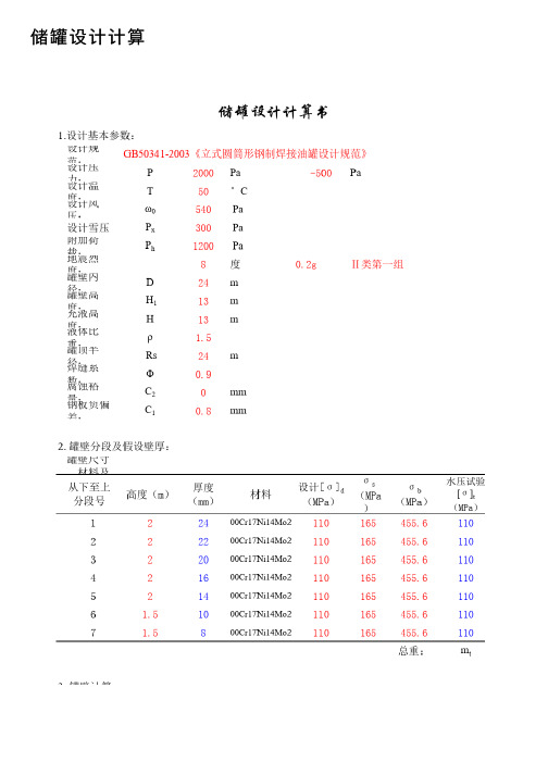
储罐设计计算注:此处的设计压⼒应为设计内压,不可等同于按液柱所确定的设计压⼒。
463.1cm 30.745KPa 0.540KPa1.001.001.38500.00罐壁筒体的临界压⼒:5.611KPat min =7.2mm H E =∑H ei=3.48mH ei ——罐壁各段当量⾼度,m ;H ei =H i (t min /t i )2.5罐壁各段当量⾼度如下:罐壁段号实际⾼度Hi (m )有效壁厚ti (mm )当量⾼度Hei(m )1223.20.112221.20.133219.20.174215.20.315213.20.446 1.59.20.8171.57.21.50罐壁设计外压: 2.2767KPa 0.60KPa如果:按6.4.9的规定选⽤。
P 0/3>[P Cr ]≥P 0/4应设置2个中间抗风圈于H E /3,2HE/3处。
6.1.2.中间抗风圈计算顶部抗风圈的实际截⾯模数 W=按图实际尺⼨计算(近似为T 型钢计算)∵ W>Wz故满⾜要求应设置3个中间抗风圈于HE/4,2HE/4,3HE/4处。
风载荷标准值P 0=2.25ωk +q=q---罐顶呼吸阀负压设定值的1.2倍∵[Pcr]>P0,故不需要设置中间抗风圈。
W z =0.083D 2H 1ωkP 0/2>[P Cr ]≥P 0/3ω0—基本风压值(<300时取300Pa)βz—⾼度Z处的风振系数,油罐取µs —风荷载体型系数,取驻点值µz —风压⾼度变化系数,ωk =βz µs µs ω0P 0>[P Cr ]≥P 0/2应设置1个中间抗风圈于H E /2处。
以此类推==5.2m in 48t E H D cr P8.771392MPa1罐底部垂直载荷 1.8009613MN A1=πDt 1.7492388m 2翘离影响系数取C L 1.4底部罐壁断⾯系数10.495433m 358.038423MN.m 9.921098MN.m 综合影响系数C z⼀般取0.4α=0.450.1404s R=D/212mKc 0.000432δ30.0192m αmax=0.45罐体影响系数Y 1⼀般取1.1m=m 1Fr5107701.9kg 罐内储液总质量8821592.2kg Fr 0.579其中:D/H1.846153828.98188MPa 199875MPa t------罐底圈壁板有效厚度0.0232mσ1<[σcr]合格0.472794m 0.026266Tg 0.35s储液晃动基本周期5.3643825sKs=1.095晃动周期系数(据D/H 按表D.3.3选取)m 1=0.25ρπD 2H动液系数(由D/H ,查D.3.4确定)6.2.2.罐壁许⽤临界应⼒[σcr ]=0.15Et/D储罐内半径储液耦连振动基本周期Q 0=10-6C z αY 1mg 地震影响系数(据Tc ,Tg ,αmax 按图D.3.1选取)地震影响系数(据Tw ,αmax 按图D.3.1选取)Tw=KsD 0.5α最⼤地震影响系数E-----设计温度下材料的弹性模量6.2.3.应⼒校核条件反应谱特征周期(按表D.3.1-1)耦连振动周期系数(据D/H 按表D.3.2选取)距底板1/3⾼度处罐壁有效厚度6.2.4.罐内液⾯晃动⾼度计算:罐内液⾯晃动⾼度h v =1.5αR竖向地震影响系数C v (7,8度地震区取1;9度地震区取1.45) N1=(m d +m t )gZ1=πD 2t/4总⽔平地震⼒在罐底部产⽣的地震弯矩M L =0.45Q 0H 罐壁横截⾯积(其中t 为底部罐壁有效厚度)总⽔平地震⼒在罐底部产⽣的⽔平剪⼒6.2.地震载荷计算:6.2.1.地震作⽤下罐壁底产⽣的最⼤轴向应⼒T c =K c H (R/δ3)0.5=产⽣地震作⽤⼒的等效储液质量M 56mm 地脚螺栓根径:d 150.67mm D b 24.256m n 48个σs235MPa1920647N16248039N 563479N 3416935N.m 15343260N迎风⾯积389.70m 2罐体总⾼16.24m 拱顶⾼度3.24m1130973N 2500.00Pa 7.2.3.储液在最⾼液位时,1.5倍计算破坏压⼒产⽣的升举⼒:2171239N16248039N 1800961N300981N A=2016.47mm 2单个地脚螺栓应⼒:σ=N b /A=149.26MPa每个地脚螺栓的承压⾯积:σ<2/3σs,合格7.4.地脚螺栓(锚栓)校核条件:N b =N/n d -W/n dN=Max[N 1,N 2,N 3,N 4]7.2.1.空罐时,1.5倍设计压⼒与设计风压产⽣的升举⼒之和:7.2.2.空罐时,1.25倍试验压⼒产⽣的升举⼒之和:设计风压产⽣的升举⼒N w =4M w /D b 设计风压产⽣的风弯矩M w =ω0A H H’N 2=PπD 2/4+Ne7.3地脚螺栓计算:N 3=P t πD 2/47.2罐体抗提升⼒计算:地脚螺栓圆直径:地脚螺栓个数:N 1=1.5PπD 2/4+N w 空罐时,设计压⼒与地震载荷产⽣的升举⼒之和地脚螺栓许⽤应⼒:地震载荷产⽣的升举⼒N e =Aσ7.3.2.单个地脚螺栓所承受的载荷:A H =H'D H'=H 1+H g Hg=Rs(1-COSθ)7.3.1.罐体总的锚固⼒为7.2.1,7.2.2.,7.2.3所计算升举⼒中的最⼤值W <N ,由于罐体⾃重不能抗倾覆⼒,故需要设置地脚螺栓W=(m t +m d )g罐体试验压⼒P t =1.25PN 4=1.5P Q πD 2/47. 地脚螺栓(锚栓)计算地脚螺栓直径:7.1地脚螺栓参数:罐体总重量。
ASME中国制造-国外储罐计算 API 620 Tank Calculations
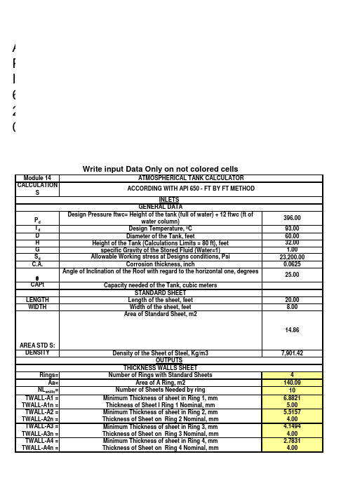
LENGTH WIDTH
STANDARD SHEET Length of the sheet, feet Width of the sheet, feet Area of Standard Sheet, m2
AREA STD S: DENSITY
Net Tanks Capacity (Barrels): Net Tanks Capacity (Gallons):
Net Tanks Capacity (Liters): Net Tanks Capacity (Mts3):
18.00 0.35 9.02 6.35 1.70 13,424.16
18.00 0.31 7.94 10.00 2.68 21,140.41
TWALL-A6 = TWALL-A6n =
TWALL-A7 = TWALL-A7n =
TWALL-A8 = TWALL-A8n =
TWALL-A9 = TWALL-A9n = TWALL-A10 = TWALL-A10n =
Vct=
Pct=
Minimum Thickness of sheet in Ring 5, mm Thickness of Sheet on Ring 5 Nominal, mm Minimum Thickness of sheet in Ring 6, mm Thickness of Sheet on Ring 6 Nominal, mm Minimum Thickness of sheet in Ring 7, mm Thickness of Sheet on Ring 7 Nominal, mm Minimum Thickness of sheet in Ring 8, mm Thickness of Sheet on Ring 8 Nominal, mm Minimum Thickness of sheet in Ring 9, mm Thickness of Sheet on Ring 9 Nominal, mm Minimum Thickness of sheet in Ring 10, mm Thickness of Sheet on Ring 10 Nominal, mm
玻璃钢罐体力学性能校核计算书(基于ASME标准)概要
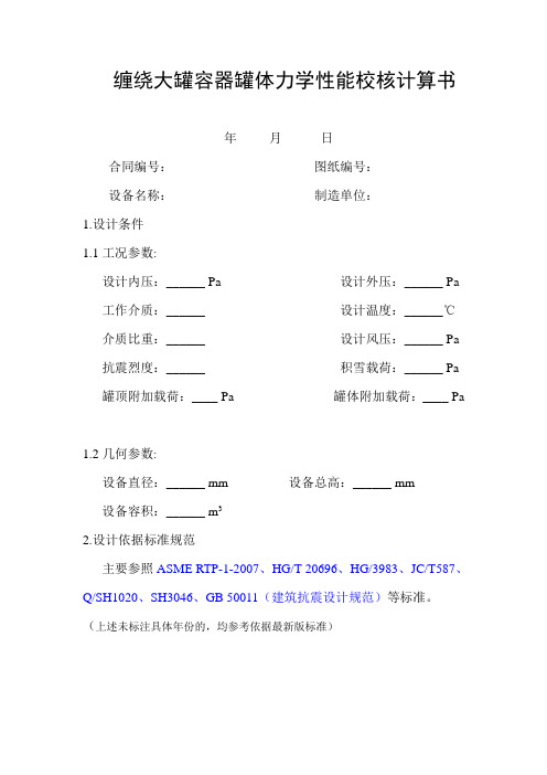
缠绕大罐容器罐体力学性能校核计算书年月日合同编号:图纸编号:设备名称:制造单位:1.设计条件1.1工况参数:设计内压:______ Pa 设计外压:______ Pa 工作介质:______ 设计温度:______℃介质比重:______ 设计风压:______ Pa 抗震烈度:______ 积雪载荷:______ Pa 罐顶附加载荷:____ Pa 罐体附加载荷:____ Pa1.2几何参数:设备直径:______ mm 设备总高:______ mm设备容积:______ m32.设计依据标准规范主要参照ASME RTP-1-2007、HG/T 20696、HG/3983、JC/T587、Q/SH1020、SH3046、GB 50011(建筑抗震设计规范)等标准。
(上述未标注具体年份的,均参考依据最新版标准)3.计算过程(计算参数、抵抗外载荷稳定性、罐体刚度、罐体强度四个方面) 3.1 计算参数根据给定工况条件,按照ASME-RTP-1-2007标准计算方法,初步得出分段计算壁厚(见附件1),具体材料力学参数如下(见表1)。
3.2 载荷计算 3.2.1封头部分3.2.1.1设计内压力计算其中:K ——为超载系数,K=1.2 P max ——为罐内为设计压力q 1 ——为罐顶单位面积自重,pa1max q KPP -=内3.2.1.2设计外压力计算其中:q2——为罐内设计负压q3——为总附加载荷,顶部活载+雪载荷,pa3.2.2筒体部分3.2.2.1 设计内压力计算其中: H ——为罐内任意截面处贮液高度。
γ ——为贮液比重。
3.2.2.2 设计外压力计算 其中: K1——为体形系数。
K1=1.0K2——为风压转换系数,K2=2.25Kz ——为风压高度变化系数, Kz=1.0 W 0——为设计风压,paK3——为滞后系数,K3=1.2。
P ——为设计外压,常压容器取500pa 。
3.2.2.3 地震载荷计算(采用动液压力理论)其中: Cz ——为综合影响系数,取Cz=0.4;αmax ——为地震影响系数,取αmax =0.23W ——为产生地震载荷的贮罐总重量,取 321q q qP ++=外H KPγ+=max P 内P K W K K K z 3021P +=外WC Q z m ax 0α='W F W r =Fr ——为动液系数W'——为贮罐内贮液重量,N地震弯矩:其中: Hw ——为贮罐底面至贮液面的高度,m3.2.2.4风载荷计算 (取风载荷作用于贮罐重心位置)其中: A ——为风载荷作用面积,A=H ×DN ;C ——为形状系数,C=0.7风弯距:3.3 筒身应力计算 3.3.1 环向应力3.3.1.1 环向薄膜应力计算3.3.1.2底端部弯矩引起的环向应力其中: M ——为底部最大弯矩3.3.1.3组合环向应力拉应力: 其中:为有正压时,其他为零;2H M w0Q =AW CK Q z 0=[]拉压y y y y σσσσ≤+=21HQ M 21=()tDNP P y 21外内-=σ2111226tD MD y =σ1y σ压应力: 其中: 为有负压时,其他为零。
储罐计算

D1 15.75
(°) 24.62432 (°) 2.902293 球面拱顶展开计算是按"球罐 展开长L1(mm) 7163.132 和大型储罐"内的有关内容编 大弧长AB(mm) 4163.34 的有关符号和简图请参看本书 小弧长CD(mm) 542.6548 217、218和219页。 大半径R1(mm) 8665.302 小半径R2(mm) 961.2329 大弦长L1(mm) 4123.411 小弦长L2(mm) 535.4773
0 -14.6314 -11.0951 -11.0951
549.5628 35746.65
储罐保温表面积,体积和重量 保温厚度 保温密度 罐壁厚度 表面积 体积 重量 2 3 mm kg/m3 mm m m kg 100 200 10 558.6443 55.86443 11172.89
2) 焊缝系数 φ 0.9 h
间距(mm)
经向的面积折算系数
经向的组合截面形心 距离(mm)
间距(mm) 经向的面积折算系数
经向的组合截面形心 距离(mm)
பைடு நூலகம்
Pa 650 输入数据 te-球壳顶板有效厚度(mm) h1-纬向肋宽度(mm) b1-纬向肋厚度(mm) L1-纬向肋在经向的间距(mm) n1-纬向肋与顶板在经向的面积折算系数 e1-纬向肋与顶板在经向的组合截面形心 (0点)到顶板中面的距离(mm) h2-经向肋宽度(mm) b2-经向肋厚度(mm) L2-经向肋在经向的间距(mm) n2-经向肋与顶板在经向的面积折算系数 e2-经向肋与顶板在经向的组合截面形心 (0点)到顶板中面的距离(mm)
带肋球壳
罐顶厚度初算 拱顶半径 Rn (m) 18.96 拱顶厚度 t (mm) 7.9632 初算名度厚度 t (mm) 10 拱顶体积 m3 2.054067 拱顶重 kg 16124.43 Gk Pa 1012.315 附加载荷 Pa 1250 设计外压 Pa 3261.256 自支锥顶厚度 t (mm) 11.22522 自支拱顶厚度 t (mm) 9.814122 拱顶名度厚度 t (mm) 10 球面拱顶展开计算 输入数据 顶板块数n 系数a 系数b 中心顶板孔D2 12 25 30 1.92 φ φ
15-常压API 650储罐

ATMOSPHERIC API 650 STORAGE TANKS常压API 650储罐FOREWORD序言This specification covers the minimum requirements for the design and fabrication of Field Erected Steel Storage Tanks used in the petroleum and petrochemical industries.This specification is intended to supplement API Standard 650, which is part of this specification. Paragraph numbers of this specification correspond to those in API 650. Paragraph numbers not found in API 650 are new paragraphs.该技术规范包括用于石油和石油化工业现场安装的钢制储罐设计和制造的最低要求。
该技术规范是对API 标准650的补充,是该技术规范的一部分。
该技术规范的段落数与API650的段落数相对应。
API 650中没有的段落为新增加的段落。
Paragraphs shall be highlighted as shown below to indicate the type of change from the API Standard:段落应加以标记(如下所示),以标明由API标准变化的情况:(Addition) New paragraph or supplemental requirements/clarifications to an existing paragraph.(新增)新增段落或对现有段落的补充要求/说明(Deleted) Paragraph deleted.(删减)段落已删除(Revision) A revision has been made as required.(修改)按要求已进行的修改。
- 1、下载文档前请自行甄别文档内容的完整性,平台不提供额外的编辑、内容补充、找答案等附加服务。
- 2、"仅部分预览"的文档,不可在线预览部分如存在完整性等问题,可反馈申请退款(可完整预览的文档不适用该条件!)。
- 3、如文档侵犯您的权益,请联系客服反馈,我们会尽快为您处理(人工客服工作时间:9:00-18:30)。
。主要问题在于未考虑地震倾覆。
储罐计算目录 1.储罐估重量 2.储罐整体计算 3.储罐抗震计算 4.地脚螺栓计算 5.带肋球壳计算 6.罐顶罐壁有效连接面积计算 7.外浮顶罐抗风圈计算 8.拱顶扇形板尺寸计算 9明: 储罐估重 应提供参考系数! 整体计算 基本无误 抗震计算 基本无误 带地脚螺栓时的抗震 有疑问。 地脚螺栓计算 未再次校核 对风载中的一项值有疑问! 带肋球壳计算,未再次校核,但估计没大问题! 罐顶罐壁有效连接面积计算,经过使用比较准确 外浮顶罐抗风圈计算,未校核,也未经过实践! 拱顶扇形板尺寸计算,基本无误! 锥顶板尺寸计算,基本无误! 必须增加外浮盘的计算! 本计算适用于高径比小于1.6的储罐。主要问题在于未考虑地震 如需考虑地震倾覆,可参考API650相关章节。