思科IOU模拟器拓扑搭建教程
思科中文版WEB-IOU使用手册
思科超强模拟器WEB-IOU使用手册
本教程里所使用工具:WEB-IOU、CRT、VM9.0,我已打包上传,请自行下载研究!WEB-IOU里的镜像及iourc都已内置,无需改动其他!
最新版镜像:路由器为15.2版本交换机为:L2Golden版本
原版WEB-IOU为英文版,为方便大家使用而简单汉化网页,不喜勿喷!网页背景如需自定义请
e-mail:索取教程,打造个性化的WEB-IOU!后续会有视频教程发布
因为这是第一次做教程,做的有点粗略,还请各位见谅,菜鸟教程,老鸟勿喷!
在此得感谢那些提供出如果强大模拟器的老鸟们!
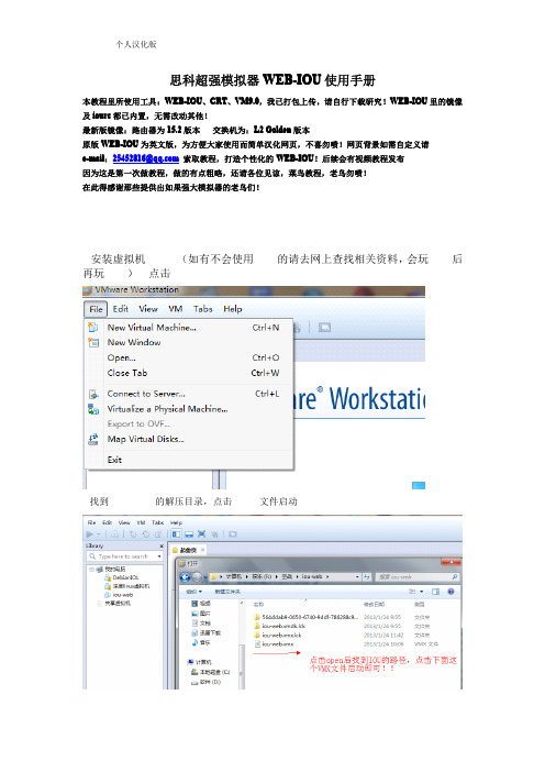
1.安装虚拟机VM9.0(如有不会使用VM的请去网上查找相关资料,会玩VM后再玩IOU)---点击open
2.找到WEB-IOU的解压目录,点击VMX文件启动
3.启动过程...选择第一个启动(默认第一个)
4.启动成功后进入登录界面:用户名root密码cisco
生成VM1和VM8两张网卡,此处我用的是VM8网卡)
如果地址没在同一网段,请下图的命令进行地址修改!
6.确保linux能和本机VM8网卡通信!
7.连通性没问题后,即可用浏览器输入linux 的IP 地址进入WEB-IOU 界面,以下图片就是对WEB-IOU 的一些使用技巧和注意事项!(网页的背景图片不喜勿喷,可以邮件给我教你自定义修改背景图片)
总结:总的来说就是先让linux和本机能够正常通信...在通信的基础上去访问linux里面的WEB-IOU,访问成功后,就得学着如果使用IOU来搭建拓扑,命令write保存配置!
注意点:工具里面的导出和导入实验我个人认为作用不大,因为导出来你用其他软件不能用!。
IOU教程

Cisco思科模拟器大家都不陌生,大部分初学者都是使用GNS3和CiscoPacketTracer这两款。
其中我们一般推荐使用GNS3为主。
原因是GNS3使用的IOS是真实的镜像,命令集很完整。
而CiscoPacketTracer是软件编程实现的,命令集是不完整的。
但GNS3也存在一些缺陷,比如消耗资源多,交换功能不完整等。
因此,更高端的模拟器IOU 就出现了。
下面和大家分享下关于IOU的一些情况。
1.问:什么是IOU?1.答:IOU是IOS on UNIX的简写。
也称为IOL(IOS on Linux)。
是运行在UNIX/Linux环境下的IOS模拟器。
其命令集也是完整的。
2.问:什么是Web IOU?2.答:IOU的拓扑搭建需要使用命令行和vi编辑器,不够直观和方便。
因此有高手进行加工,做出Web操作界面,称为WebIOU。
3.问:GNS3和IOU的区别有哪些?3.答:使用场合区别。
小拓扑建议使用GNS3,大型及超大型拓扑使用IOU。
交换功能区别。
IOU的交换功能强于G NS3。
软件版本区别。
IOU可以使用15.0的最新IOS,功能更加强大。
4.问:Web IOU安装需要哪些条件?4.答:第一种情况,在纯净的Linux环境中安装WebIOU。
第二种情况,在Windows下使用Vmware安装WebIOU。
一般我们的电脑都是安装Windows系统。
所以,建议刚开始,使用第二种情况。
5.下面以Vmware9.0.2和IOU Web 1.2.0.37为对象给大家看看Cisco Web IOU 的使用。
感谢大拿Jeff对WebIOU的技术支持。
思科模拟器单臂路由实验
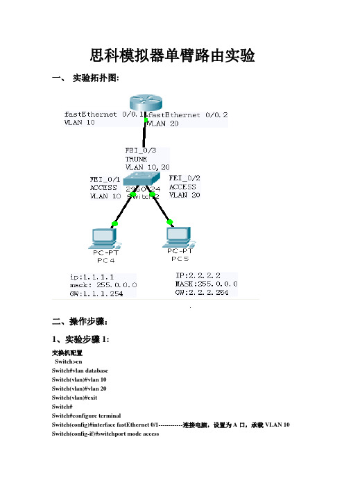
思科模拟器单臂路由实验一、实验拓扑图:二、操作步骤:1、实验步骤1:交换机配置Switch>enSwitch#vlan databaseSwitch(vlan)#vlan 10Switch(vlan)#vlan 20Switch(vlan)#exitSwitch#Switch#configure terminalSwitch(config)#interface fastEthernet 0/1------------连接电脑,设置为A口,承载VLAN 10 Switch(config-if)#switchport mode accessSwitch(config-if)#switchport access vlan 10Switch(config-if)#exitSwitch(config)#interface fastEthernet 0/2------------连接电脑,设置为A口,承载VLAN 20Switch(config-if)#switchport mode accessSwitch(config-if)#switchport access vlan 20Switch(config-if)#exiSwitch(config)#interface fastEthernet 0/3--------连接路由器,设置为T口,承载VLAN 10,20Switch(config-if)#switchport mode trunkSwitch(config-if)#switchport trunk allowed vlan 10,20Switch(config)#exitSwitch#wr路由器配置Router>enRouter#configure terminalRouter(config)#interface fastEthernet 0/0--------进入路由器0/0口Router(config-if)#no shutdown -------开启路由器0/0口Router(config-if)#exitRouter(config)#interface fastEthernet 0/0.1-------进入路由器0/0.1逻辑子接口Router(config-subif)#no shutdown -------开启路由器0/0.1口Router(config-subif)#encapsulation dot1Q 10 ---让路由器0/0.1逻辑子接口承载vlan10 Router(config-subif)#ip address 1.1.1.254 255.255.255.0----给路由器0/0.1逻辑子接口起IP地址(即PC4的网关)Router(config-subif)#exitRouter(config)#interface fastEthernet 0/0.2-------进入路由器0/0.2逻辑子接口Router(config-subif)#no shutdown -------开启路由器0/0.2口Router(config-subif)#encapsulation dot1Q 20---让路由器0/0.1逻辑子接口承载vlan20 Router(config-subif)#ip address 2.2.2.254 255.255.255.0-------给路由器0/0.2逻辑子接口起IP 地址(即PC5的网关)Router(config-subif)#exitRouter(config)#exitRouter#wr三、验证配置结果:在实验步骤3、实验步骤4完成后,分别验证结果:验证方法如下:1、PC4配置相应的IP地址和网关后,与PC5之间互相可以ping通;2、用show ip route观察交换机上的路由表,认识哪些是直连路由,哪些是静态路由信息,哪些是缺省路由;Router>show ip routeCodes: C - connected, S - static, I - IGRP, R - RIP, M - mobile, B - BGPD - EIGRP, EX - EIGRP external, O - OSPF, IA - OSPF inter areaN1 - OSPF NSSA external type 1, N2 - OSPF NSSA external type 2E1 - OSPF external type 1, E2 - OSPF external type 2, E - EGPi - IS-IS, L1 - IS-IS level-1, L2 - IS-IS level-2, ia - IS-IS inter area* - candidate default, U - per-user static route, o - ODRP - periodic downloaded static routeGateway of last resort is not set1.0.0.0/24 is subnetted, 1 subnetsC 1.1.1.0 is directly connected, FastEthernet0/0.12.0.0.0/24 is subnetted, 1 subnetsC 2.2.2.0 is directly connected, FastEthernet0/0.2。
IOU拓扑生成器使用指南

IOU拓扑生成器使用指南
第一步,运行文件
注意,这两个文件一定要在一个文件夹下
选择需要的路由器跟交换机的个数,以及存放的位置,注意,这里选择的文件夹要是英文的,因为它会被导入cdlinux里面
,在这里,我选择了一个路由器,一个交换机,存放在c盘的iou文件夹下,然后点击设置,找到自己电脑中的(跟winscp.exe在一个文件夹里),以及putty.exe
第二步
选择路由器跟交换机的模块,别忘了点确定
第三步
具体连线方式与小凡模拟器类似
连完以后,依次点击“生成netmap”,“生成执行文件”搞定iou运行所需要的文件当你点击生成执行文件时,他会问你
这里填的文件夹就是我们在第一步设置的文件夹的名字
在这里,如果仅仅是想生成这些文件的话,生成完毕就可以退出了
如果想继续运行设备,点击控制台
第四步
这时候我们看一下虚拟机的地址
注意,目前这个生成器配套cdlinux是大神的cisco-iou-ccie-v4-ts-rack-livecd-v2.0.iso
虚拟机开启后,我们想更新虚拟机的密钥,点击
你会看到这个
这里,程序会自动为你添加密钥,如果没有自动添加,按a即可,上图是添加成功的情况,这样就可以关闭窗口了
如果出现的是这样
恭喜你,已经同步过了
同步过后,我们就可以导入刚才生成的文件了,点击
稍等片刻,因为我们要把L2iou的ios导入
导入完成,我们就可以开启所有设备了
点击
将会开启所有的路由器与交换机
注,第一次可能会报错,再点一次就好了
如果这时候你想登陆所有的设备,就点击如果不想,就从下面一台一台的点击。
IOU+自建拓扑
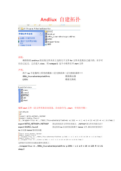
Andliux 自建拓扑前提:确保你的andlinux的安装文件夹有上边的几个文件for文件夹是我自己建立的,名字可以自己定义,之后进入cisco,用notepad 2 这个小软件打开start文件声明:两个ios不是像网上所传的模拟三层交换机和二层交换机那样!!!i86bi_linux-adventerprisek9-ms 模拟路由器L2IOU 模拟交换机编辑start文件(此文件用来启动设备,启动命令为. ./start 中间有空格)export NETIO_NETMAP=./NETMAP 指定你的拓扑文件所在的地方。
./NETMAP指文件在同级目录下export IOURC=./iourc3 指定你的ios启动时候读取哪个license文件。
解决同时使用两个ios启动报license错误的问题这样就可以同时启动路由器和交换机了。
../wrapper-linux -m ../i86bi_linux-adventerprisek9-ms -p 2001 -- -s 1 -e 0 -n 16 -m 128 -R -U 1 & sleep 2../wrapper-linux 指定读取上级文件夹的wrapper-linux运行文件。
-m ../i86bi_linux-adventerprisek9-ms 指定使用的ios的路径在上级目录。
-p 2001 指定telnet端口号-- -s 1 -e 0 -n 16 -m 128 -R -U 1 & sleep 2 是要发送给ios的选项-s 1 设备使用一个串口模块(包含四个接口)-e 0 不使用一台口模块(一个模块包含四个接口)-n 16 指定设备nvram的大小(默认为16K)-m 128 指定设备的内存大小(默认128M)-R 忽略iourc文件内的选项-U 不使用unix文件系统位置1 设备的编号(与NETMAP文件中设备的编号呼应)& sleep2 设备启动后等待2s后启动下一台设备。
cisco-iou-ccie思科IOU模拟器下载使用教程
本文档的主要目的,旨在让大家了解CDlinux-IOU是什么,可以做什么,并且能让大家快速入门。
1 CDlinux-IOU1.1 CiscoIOUCis coIOU全称是Cis co IOS on Unix ,最早的版本是运行于Solaris,后来出现了iMAC和UNIX 版本。
目前的I OU 只有L3IOU ,对于模拟交换机的L2IOU 还没放出来,目前CCIE RS的排错考试就是用IOU搭建的。
1.2 CDlinux-IOUCDLinux-IOU是集成了IOU的一个Linux Live CD发行版由鼎鼎大名的撒加制作,目前已经发布了CDLinux-IOU 2.0的版本。
其作用主要皆在帮助那些需要进行CCIE TS的考生有相应的模拟环境的用户使用,并且资源占用非常可观,镜像大小依旧保持在60M左右。
该版本已经可以支持自定义拓扑,因为在系统启动的时候没有没有加载任何IOU的镜像,同时提供了启动设备的脚本,故我们现在可以用CDLinux-IOU 2.0来做实验。
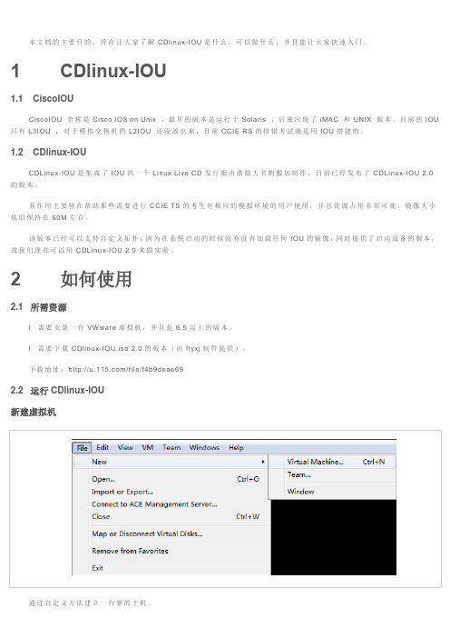
2 如何使用2.1 所需资源l 需要安装一台VWware虚拟机,并且是6.5以上的版本。
l 需要下载CDlinux-IOU.is o 2.0的版本(由flyxj制件提供)。
下载地址:/file/f4b9deae692.2 运行CDlinux-IOU新建虚拟机通过自定义方法建立一台新的主机。
大都只要默认即可,到以下点时,只要注意选择CDlinux-IOU.iso的路径。
选择安装Linux系统。
然后到了如下可以选择NAT或者桥接,都行桥接的话,后续在Linux系统要设置,#ifconfig eth0 192.168.0.1 netm ask 255.255.255.0 up,初学者可用NAT。
接下来一路默认即可完成虚拟机的安装。
完成后,如下:初次运行等待一段时间后,即可出现如下画面(注,2.0版里面有不同的人作的拓扑和启动画面)这个是由flyxj制件提供的,show后,可以看到IP地址,以便用SSH登录。
思科模拟器7.2使用教程

思科模拟器7.2使用教程简介思科模拟器是一款用于模拟网络设备的软件,可以帮助用户进行网络配置和故障排除的实验。
本教程将介绍如何使用思科模拟器7.2进行网络设备模拟和配置。
安装思科模拟器7.2首先,您需要从思科官方网站下载思科模拟器7.2的安装包。
安装包通常以.exe格式提供,您只需双击安装包并按照提示进行安装即可。
启动思科模拟器7.2安装完成后,您可以在开始菜单中找到思科模拟器7.2的快捷方式,双击打开即可启动程序。
启动后,您将看到思科模拟器的主界面。
创建网络拓扑在思科模拟器中,您可以创建多个网络设备的拓扑,以模拟真实的网络环境。
要创建网络拓扑,请按照以下步骤进行操作:1.在思科模拟器的主界面中,点击菜单栏的“File”选项。
2.在下拉菜单中,选择“New”来创建一个新的拓扑。
3.在弹出的对话框中,选择您想要模拟的设备类型,并设置所需的数量。
4.点击“OK”按钮,即可创建一个新的网络拓扑。
配置网络设备创建完网络拓扑后,您可以开始配置网络设备。
思科模拟器提供了交互式的命令行界面,可以让您像在真实设备上一样进行配置。
要配置网络设备,请按照以下步骤进行操作:1.在思科模拟器的主界面中,选择您想要配置的设备。
2.右键点击设备,选择“Console”以打开设备的命令行界面。
3.在命令行界面中,您可以输入命令来进行设备的配置。
4.配置完成后,您可以保存配置,并在需要时加载配置。
模拟网络流量除了配置网络设备,思科模拟器还可以模拟网络流量,帮助您进行网络性能测试和故障排查。
要模拟网络流量,请按照以下步骤进行操作:1.在思科模拟器的主界面中,选择您想要模拟的设备。
2.右键点击设备,选择“Send/Receive”以打开设备的流量模拟界面。
3.在流量模拟界面中,您可以设置流量的源和目的地,并配置其他相关参数。
4.点击“Start”按钮,即可开始模拟网络流量。
运行网络拓扑实验思科模拟器还支持创建和运行网络拓扑实验,以帮助用户在模拟环境中进行网络配置和故障排查。
IOU拓扑

在这里,感谢撒加提供的基于VMware的L2IOU的系统平台,为我们学习Cisco提供非常大的助力!本人在撒加的基础上对拓扑做了更改,方便大家使用。
1、对“NETMAP”做的修改,具体内容如下:(备注:R1=1;R2=2;R3=3;R4=4;R5=5;R6=6;F-R=7;SW1=8;SW2=9;SW3=10;SW4=11)1:0/0 8:0/01:0/1 9:0/01:0/2 10:0/01:0/3 11:0/01:1/0 7:0/01:1/2 2:1/32:0/0 8:0/12:0/1 9:0/12:0/2 10:0/12:0/3 11:0/12:1/0 7:0/12:1/2 3;1/33:0/0 8:0/23:0/1 9:0/23:0/2 10:0/23:0/3 11:0/23:1/0 7:0/23:1/2 4:1/34:0/0 8:0/34:0/1 9:0/34:0/2 10:0/34:0/3 11:0/34:1/0 7:0/34:1/2 5:1/35:0/0 8:1/05:0/1 9:1/05:0/2 10:1/05:0/3 11:1/05:1/0 7:1/05:1/2 6:1/36:0/0 8:1/16:0/1 9:1/16:0/2 10:1/16:0/3 11:1/12、对"start.sh"做了修改,具体如下/wrapper-linux -m ./i86bi_linux-adventerprisek9-ms -p 2001 -- -e 1 -s 1 1 & sleep 10./wrapper-linux -m ./i86bi_linux-adventerprisek9-ms -p 2002 -- -e 1 -s 1 2 & sleep 10./wrapper-linux -m ./i86bi_linux-adventerprisek9-ms -p 2003 -- -e 1 -s 1 3 & sleep 10./wrapper-linux -m ./i86bi_linux-adventerprisek9-ms -p 2004 -- -e 1 -s 1 4 & sleep 10./wrapper-linux -m ./i86bi_linux-adventerprisek9-ms -p 2005 -- -e 1 -s 1 5 & sleep 10./wrapper-linux -m ./i86bi_linux-adventerprisek9-ms -p 2006 -- -e 1 -s 1 6 & sleep 10./wrapper-linux -m ./i86bi_linux-adventerprisek9-ms -p 2007 -- -e 0 -s 2 7 & sleep 10./wrapper-linux -m ./i86bi_linuxl2-upk9-ms -p 3001 -- -e 4 -s 0 8 &sleep 10./wrapper-linux -m ./i86bi_linuxl2-upk9-ms -p 3002 -- -e 4 -s 0 9 &sleep 10./wrapper-linux -m ./i86bi_linuxl2-upk9-ms -p 3003 -- -e 4 -s 0 10 &sleep 10./wrapper-linux -m ./i86bi_linuxl2-upk9-ms -p 3004 -- -e 4 -s 0 11 &sleep 103、拓扑图:感谢HC2的指正,第一张拓扑图的链接关系为R1:E0/0<-->SW1:E0/0R1:E0/1<-->SW2:E0/0R1:E0/2<-->SW3:E0/0R1:E0/3<-->SW4:E0/0R2:E0/0<-->SW1:E0/1R2:E0/1<-->SW2:E0/1R2:E0/2<-->SW3:E0/1R2:E0/3<-->SW4:E0/1R3:E0/0<-->SW1:E0/2R3:E0/1<-->SW2:E0/2R3:E0/2<-->SW3:E0/2R3:E0/3<-->SW4:E0/2R4:E0/0<-->SW1:E0/3R4:E0/1<-->SW2:E0/3R4:E0/2<-->SW3:E0/3R4:E0/3<-->SW4:E0/3R5:E0/0<-->SW1:E1/0R5:E0/1<-->SW2:E1/0R5:E0/2<-->SW3:E1/0R5:E0/3<-->SW4:E1/0 R6:E0/0<-->SW1:E1/1 R6:E0/1<-->SW2:E1/1 R6:E0/2<-->SW3:E1/1 R6:E0/3<-->SW4:E1/1。
- 1、下载文档前请自行甄别文档内容的完整性,平台不提供额外的编辑、内容补充、找答案等附加服务。
- 2、"仅部分预览"的文档,不可在线预览部分如存在完整性等问题,可反馈申请退款(可完整预览的文档不适用该条件!)。
- 3、如文档侵犯您的权益,请联系客服反馈,我们会尽快为您处理(人工客服工作时间:9:00-18:30)。
交流群: 思科 CCNP 交流群:69721386Here’s an example topology for Cisco IOU to help you get started:In this example, SF is an IOU instance running on host “solaris”. IOUlive is also running on this host, bridging SF’s Ethernet0/0 interface to my physical network (and to the world).SJ1, SJ2, and SJ3 are IOU instances running on host “helium”.The Ethernet1/0 interface on SF is connected to Ethernet0/1 on SJ1 are connected, even though they are on separate physical hosts.The Ethernet0/0 interfaces on SJ1, SJ2, and SJ3 are connected, sharing a common network segment.Last, SJ2 and SJ3 are connected via their Serial1/0 interfaces.Hopefully, this should be good enough to demonstrate the various options for connecting IOU instances.The NETMAP file交流群: 思科 CCNP 交流群:69721386When connecting IOU instances across physical hosts, the hosts should share a common NETMAP file. If it isn’t possible to use NFS, you’ll need to duplicate the file on each host. I’m not running NFS at home, so I’ve simply copied the file over to both hosts.The IOU instance IDs are assigned as follows:• SF : 100 • SF : 199 (IOUlive) • SJ1 : 151 • SJ2 : 152 • SJ3 : 153Here’s what my NETMAP file looks like:100:0@solaris 199:0@solaris100:1@solaris 151:16@helium151:0@helium 152:0@helium 153:0@helium152:1@helium 153:1@heliumConnect SF to the real worldI’ll start by firing up the SF router on solaris:$ ./unix-js-m 100 ./unix-js-IOS On Unix - Cisco Systems confidential, internal use onlyPort 0 is connected to:199:0@solarisPort 16 is connected to:151:16@helium交流群: 思科 CCNP 交流群:69721386...output snipped...Next, I’ll startup IOUlive so that SF is connected to my physical network:$ ./ioulive /dev/hme0 199Port 0 is connected to:100:0@solaris/dev/hme0 is the NIC on solaris that is connected to my network.I’ll bring up the Ethernet0/0 interface on SF:SF# conf tEnter configuration commands, one per line. End with CNTL/Z.SF(config)# interface ethernet 0/0SF(config-if)# ip address 203.0.113.2 255.255.255.0SF(config-if)# no shutdownVerify I can ping my (physical) router:SF(config-if)# do ping 203.0.113.1Type escape sequence to abort.Sending 5, 100-byte ICMP Echos to 203.0.113.1, timeout is 2 seconds:.!!!!交流群: 思科 CCNP 交流群:69721386Success rate is 80 percent (4/5), round-trip min/avg/max = 20/33/40 msSo SF, an IOU instance, has connectivity with my physical router at home, a Cisco 1811. Just for good measure, let’s add a default route and see if we can ping hosts on the Internet:SF(config-if)# exitSF(config)# ip route 0.0.0.0 0.0.0.0 203.0.113.1 203.0.113.1SF(config)# do ping 4.2.2.2Type escape sequence to abort.Sending 5, 100-byte ICMP Echos to 4.2.2.2, timeout is 2 seconds:!!!!!Success rate is 100 percent (5/5), round-trip min/avg/max = 40/50/72 msLooks like we’re all set!Bring up SJ1Now let’s bring up the SJ1 IOU instance on helium:$ ./i86bi_linux-ipbase-ms -e 1 -s 0 151 ./i86bi_linux-ipbase-***************************************************************IOS On Unix - Cisco Systems confidential, internal use onlyUnder no circumstances is this software to be provided to anynon Cisco staff or customers. To do so is likely to resultin disciplinary action. Please refer to the IOU Usage policy at交流群: 思科 CCNP 交流群:69721386 for more information.***************************************************************Port 0/0 is connected to:152:0@helium153:0@heliumPort 0/1 is connected to:100:1@solaris...output snipped...Connect SJ1 to SFNow that SJ1 is up, let’s get it connected to the SF router:SF(config)# int e1/0SF(config-if)# ip addr 10.0.0.1 255.255.255.0 10.0.0.1SF(config-if)# no shutdownSJ1# conf tEnter configuration commands, one per line. End with CNTL/Z.SJ1(config)# int e0/1SJ1(config-if)# ip address 10.0.0.2 255.255.255.0SJ1(config-if)# no shutdown交流群: 思科 CCNP 交流群:69721386Note that SF is running on the physical host “solaris”, a Solaris 8/SPARC box, and SJ1 is running on the physical host “helium”, an Ubuntu 10.04/x86 box.Let’s verify we have connectivity:SJ1(config-if)# do ping 10.0.0.1Type escape sequence to abort.Sending 5, 100-byte ICMP Echos to 10.0.0.1, timeout is 2 seconds:.!!!!Success rate is 80 percent (4/5), round-trip min/avg/max = 20/28/40 msNow we’ll bring up the Ethernet0/0 interface on SJ1 that shares a segment with SJ2 and SJ3:SJ1(config-if)# int e0/0SJ1(config-if)# ip addr 10.123.123.1 255.255.255.0 10.123.123.1SJ1(config-if)# no shutdownBring up SJ2Let’s bring up the SJ2 instance:$ ./i86bi_linux-ipbase-ms -e 1 -s 1 152 ./i86bi_linux-ipbase-***************************************************************IOS On Unix - Cisco Systems confidential, internal use onlyUnder no circumstances is this software to be provided to anynon Cisco staff or customers. To do so is likely to result交流群: 思科 CCNP 交流群:69721386in disciplinary action. Please refer to the IOU Usage policy at for more information.***************************************************************Port 0/0 is connected to:151:0@helium153:0@heliumPort 1/0 is connected to:153:1@helium...output snipped...Let’s configure the Ethernet0/0 and Serial1/0 interfaces:SJ2# conf tEnter configuration commands, one per line. End with CNTL/Z.SJ2(config)# interface ethernet 0/0SJ2(config-if)# ip address 10.123.123.2 255.255.255.0SJ2(config-if)# no shutdownSJ2(config-if)# interface serial 1/0SJ2(config-if)# ip address 10.10.23.2 255.255.255.0 255.255.255.0SJ2(config-if)# no shutdownVerify we can ping SJ1′s Ethernet0/0 interface:交流群: 思科 CCNP 交流群:69721386SJ2(config-if)# do ping 10.123.123.1Type escape sequence to abort.Sending 5, 100-byte ICMP Echos to 10.123.123.1, timeout is 2 seconds.!!!!Success rate is 80 percent (4/5), round-trip min/avg/max = 4/6/8 msBring up SJ3Now we’ll bring up the SJ3 router:$ ./i86bi_linux-ipbase-ms -e 1 -s 1 153 ./i86bi_linux-ipbase-***************************************************************IOS On Unix - Cisco Systems confidential, internal use onlyUnder no circumstances is this software to be provided to anynon Cisco staff or customers. To do so is likely to resultin disciplinary action. Please refer to the IOU Usage policy at for more information.***************************************************************Port 0/0 is connected to:151:0@helium152:0@heliumPort 1/0 is connected to:交流群: 思科 CCNP 交流群:69721386152:1@helium...output snipped...Configure Ethernet0/0 and Serial1/0:SJ3# conf tEnter configuration commands, one per line. End with CNTL/Z.SJ3(config)# interface ethernet 0/0SJ3(config-if)# ip address 10.123.123.3 255.255.255.0SJ3(config-if)# no shutdownSJ3(config-if)# interface serial 1/0SJ3(config-if)# ip address 10.10.23.3 255.255.255.0 255.255.255.0SJ3(config-if)# no shutdownVerify we can ping SJ1 and SJ2′s Ethernet0/0 interfaces:SJ3(config-if)# do ping 10.123.123.1Type escape sequence to abort.Sending 5, 100-byte ICMP Echos to 10.123.123.1, timeout is 2 seconds:.!!!!Success rate is 80 percent (4/5), round-trip min/avg/max = 1/1/1 msSJ3(config-if)# do ping 10.123.123.2交流群: 思科 CCNP 交流群:69721386Type escape sequence to abort.Sending 5, 100-byte ICMP Echos to 10.123.123.2, timeout is 2 seconds:.!!!!Success rate is 80 percent (4/5), round-trip min/avg/max = 1/1/4 msVerify we can ping SJ2 over the Serial1/0 interface:SJ3(config-if)# do ping 10.10.23.2Type escape sequence to abort.Sending 5, 100-byte ICMP Echos to 10.10.23.2, timeout is 2 seconds:!!!!!Success rate is 100 percent (5/5), round-trip min/avg/max = 12/12/12 msGreat, full connectivity so far! Let’s enable OSPF on SF and SJ1:SF(config-if)# router ospf 42SF(config-router)# network 10.0.0.1 0.0.0.0 area 0SJ1(config-if)# router ospf 42SJ1(config-router)# network 10.0.0.2 0.0.0.0 area 0SJ1(config-router)# network 10.123.123.1 0.0.0.0 area 0Make sure the OSPF adjacency between SF and SJ1 came up:交流群: 思科 CCNP 交流群:69721386SF(config-router)# do sh ip ospf neighNeighbor IDPriStateDead TimeAddressInterface10.123.123.11FULL/BDR00:00:3610.0.0.2Ethernet1/0Let’s look at the routing table on SF:SF(config-router)# do sh ip route | begin GatewayGateway of last resort is 203.0.113.1 to network 0.0.0.0C203.0.113.0/24 is directly connected, Ethernet0/010.0.0.0/24 is subnetted, 2 subnetsO10.123.123.0 [110/20] via 10.0.0.2, 00:00:50, Ethernet1/0C10.0.0.0 is directly connected, Ethernet1/0S*0.0.0.0/0 [1/0] via 203.0.113.1Inject default route into OSPFSince SF has a route to the world, let’s inject a default route there into OSPF:SF(config-router)# default-information originate default-Make sure it shows up on SJ1:SJ1(config-router)# do sh ip route | begin GatewayGateway of last resort is 10.0.0.1 to network 0.0.0.0交流群: 思科 CCNP 交流群:69721386O*E2 0.0.0.0/0 [110/1] via 10.0.0.1, 00:00:44, Ethernet0/110.0.0.0/8 is variably subnetted, 4 subnets, 2 masksC10.0.0.0/24 is directly connected, Ethernet0/1L10.0.0.2/32 is directly connected, Ethernet0/1C10.123.123.0/24 is directly connected, Ethernet0/0L10.123.123.1/32 is directly connected, Ethernet0/0Configure default route on SJ2 and SJ3On SJ2 and SJ3, let’s configure a default route towards SJ1:SJ2(config-if)# ip route 0.0.0.0 0.0.0.0 10.123.123.1SJ3(config-if)# ip route 0.0.0.0 0.0.0.0 10.123.123.1 routeMake sure SF can talk to SJ2 and SJ3:SF(config-router)# do ping 10.123.123.2Type escape sequence to abort.Sending 5, 100-byte ICMP Echos to 10.123.123.2, timeout is 2 seconds:!!!!!Success rate is 100 percent (5/5), round-trip min/avg/max = 28/44/60 msSF(config-router)# do ping 10.123.123.3交流群: 思科 CCNP 交流群:69721386Type escape sequence to abort.Sending 5, 100-byte ICMP Echos to 10.123.123.3, timeout is 2 seconds:!!!!!Success rate is 100 percent (5/5), round-trip min/avg/max = 28/52/88 msConfigure NAT on SFNow that we have full connectivity, let’s configure NAT on the SF router so that SJ1, SJ2, and SJ3 can talk to the outside world:SF(config-router)# interface ethernet 0/0SF(config-if)# ip nat outsideSF(config-if)# interface ethernet 1/0SF(config-if)# ip nat insideWe’ll need an ACL matching the source addresses to match, of course:SF(config-if)# ip access-list standard NAT access-SF(config-std-nacl)# permit 10.0.0.0 0.0.0.255SF(config-std-nacl)# permit 10.123.123.0 0.0.0.255SF(config-std-nacl)# permit 10.10.23.0 0.0.0.255Last, we’ll use “ip nat …” to tell SF how to work its magic:SF(config-std-nacl)# ip nat inside source list NAT int e0/0 overload intVerify connectivity交流群: 思科 CCNP 交流群:69721386At this point, all routers should have connectivity to the outside world. Let’s verify from SJ2 and SJ3 by pinging a couple of well-known public DNS servers:SJ2(config)# do ping 4.2.2.2Type escape sequence to abort.Sending 5, 100-byte ICMP Echos to 4.2.2.2, timeout is 2 seconds:!!!!!Success rate is 100 percent (5/5), round-trip min/avg/max = 28/55/128 msSJ3(config)# do ping 8.8.8.8Type escape sequence to abort.Sending 5, 100-byte ICMP Echos to 8.8.8.8, timeout is 2 seconds:!!!!!Success rate is 100 percent (5/5), round-trip min/avg/max = 80/100/120 msLooks like everything is working properly.Verify Internet connectivityLast, just for good measure, let’s connect to the web server this site runs on and issue a request:SJ3(config)# do telnet 206.125.175.18 80Trying 206.125.175.18, 80 ... OpenHEAD / HTTP/1.0交流群: 思科 CCNP 交流群:69721386HTTP/1.0 200 OKDate: Sat, 22 Jan 2011 22:52:01 GMTServer: Apache/2.2.17 (FreeBSD) mod_ssl/2.2.17 OpenSSL/0.9.8nX-Pingback: /xmlrpc.phpLink: <http://wp.me/nzh6>; rel=shortlinkConnection: closeContent-Type: text/html; charset=UTF-8[Connection to 206.125.175.18 closed by foreign host]SummaryThis post demonstrated a number of concepts that should be useful for those wanting to use IOU.First, we showed how the routers connect “physically”.Second, we showed how to construct a working NETMAP file to match our topology.Third, we started up our IOU instances and connect them across hosts and to the outside world.Fourth, we configured our routers (even configuring OSPF).Last, we showed how to verify we had connectivity with the outside world.交流群: 思科 CCNP 交流群:69721386I hope this post was helpful. I welcome your feedback in the comments section below!。