LSD4WN-2N717M91驱动程序使用说明书_V1.0.1.170118
YASKAWA717使用说明
安川PLC控制软件CP-717内部功能完善,通讯及运算功能强大,能对PLC及变频器实施精密控制.
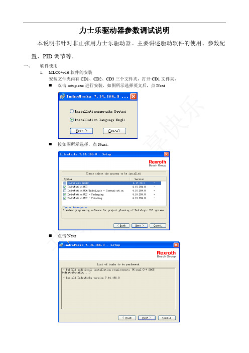
1)高速扫描程序结构
N01S01中的高速扫描程序主要实现对起升机构,大车机构,小车机构,俯仰机构的运行控制,位置检测及对各机构变频器实施精密控制,并实时采集变频器的各项参数,进行运算判断保证各机构安全,可靠的运行.
215通讯
RIO-2000单元
I/O模块I
I/O模块I
I/O模块I
I/O模块I
I/O模块I
I/O模块I
216通讯
大车PG小车PG
大车PG
起升PG
6)故障查找流程
联机打开程序的步骤
程序寄存器,MBnnnnnn对应MWnnnnn的一位
MWnnnnn及MBnnnnnn在全部程序中通用
DWnnnnn
DBnnnnnn
子程序寄存器,DBnnnnnn对应DWnnnnn的一位
DWnnnnn及DBnnnnnn只在子程序中有效
Iwnnnnn
IBnnnnnn
输入寄存器,IBnnnnnn对应IWnnnnn的一位
IWnnnnn及IBnnnnnn在全部程序中通用
Ownnnnn
OBnnnnnn
输出寄存器,OBnnnnnn对应OWnnnnn的一位
OWnnnnn及OBnnnnnn在全部程序中通用
SWnnnnn
SBnnnnnn
系统寄存器,SBnnnnnn及SWnnnnn为系统专用寄存器,有特定含义,用户只可利用,不可定义.
MB003
3
4
5
6
7
8
9
A
B
C
D
E
D1驱动器操作使用手册

D1驅動器使用者操作手冊第1版2010年12月13號D1驅動器使用者操作手冊此頁空白目錄關於本操作手冊 (iv)產品警告........................................................................................................................................................................................ i v 修訂記錄. (v)1:規格介紹 (1)1.1: 安規認證 (2)1.2: 伺服驅動器基本規格 (2)1.3: 驅動器尺寸規格 (4)1.4: 驅動器安裝 (5)1.5: 電腦規格需求 (5)2:動作原理 (6)2.1: 操作模式(Modes) (7)2.1.1: 位置模式(Position mode) (7)2.1.2: 使用電壓指令之兩種模式(V command) (8)2.1.3: 使用PWM指令之兩種模式(PWM command) (8)2.1.4: 獨立作業模式(Stand alone) (8)2.2: 編碼器(Encoders) (9)2.2.1: 數位式(Digital) (9)2.2.2: 類比式(Analog) (9)2.3: 編碼器緩衝輸出與模擬編碼器輸出 (10)2.4: 路徑規畫(Path Planning) (11)2.4.1: 位置(Position) (11)2.4.2: 速度(Velocity) (11)2.4.3: 加速度(Acceleration) (11)2.4.4: 平滑運動(Smooth Factor) (11)2.4.5: 緊急停止(Emergency Stop) (12)2.5: 伺服迴路(Control Loops model) (12)2.6: 伺服增益(Common Gain ) (12)2.7: 移動與整定(Move & Settle) (13)2.7.1: 跟隨誤差(Postion error) (13)2.7.2: 目標框(Target radius) (13)2.7.3: 移動與整定之時間總和(Total time) (13)2.8: 誤差補償(Error map誤差補償) (14)2.9: 速度漣波(Velocity Ripple) (15)2.10: 激磁(Enable) (15)2.10.1: 步進模式(SM Mode) (15)2.10.2: 相位初始化(Phase Initialization) (15)2.11: 馬達基本規格 (16)2.11.1: 連續電流(Continuous Current) (16)2.11.2: 瞬間電流(Peak Current) (16)2.11.3: 反電動勢(Back EMF) (16)2.12: 驅動器基本規格 (16)2.12.1: 驅動器內部電源 (16)2.13: 均方根與振幅值(Rms與Amplitude) (17)2.14: 基本常用物理量(Basic Variable List) (17)3:配線 (19)3.1: 系統結構和配線 (20)3.1.1: 總配線圖 (20)3.1.2: 接頭規格 (21)3.2: 主電路配線 (22)3.3: 馬達配線 (23)3.4: 回生電阻配線(回生電阻為選配件) (23)3.5: 控制用電源與煞車配線 (24)3.6: RS232通訊(CN1) (25)3.7: 控制信號配線(CN2) (26)3.7.1: 數位輸入配線圖 (27)3.7.2: 數位輸出配線圖 (29)3.7.3: 脈波指令輸入配線圖 (31)3.7.4: 編碼器回授脈波輸出配線圖 (32)3.7.5: 類比指令輸入配線圖 (33)3.8: 回授信號配線(CN3) (35)3.8.1: 數位式增量型編碼器配線圖 (36)3.8.2: 類比式增量型編碼器配線圖 (36)3.9.1: 馬達動力線 (38)3.9.2: 回授信號線 (38)3.9.3: 控制信號線 (39)3.9.4: RS232通信線 (39)3.9.5: 接頭配件包 (40)3.9.6: EMC配件包 (40)3.9.7: 回生電阻 (40)3.9.8: 散熱片 (40)4:驅動器設定 (41)4.1: 安裝與連線 (42)4.1.1: 程式安裝檔 (42)4.1.2: 連線設定 (43)4.1.3: 人機畫面 (44)4.2: 參數設定中心(Configuration Center) (45)4.2.1: 馬達類型設定(Motor Type) (46)4.2.2: 編碼器參數設定(Encoder Parameter) (50)4.2.3: 霍爾感測器(Hall sensors) (55)4.2.4: 操作模式設定(Operation Mode) (56)4.2.5: 參數設定完成步驟 (58)4.3: 自動相位初始設定中心(Auto phase center) (59)4.3.1: 自動相位初始化前置作業 (60)4.3.2: 自動相位初始設定步驟 (60)4.3.3: 自動相位初始化注意事項 (61)4.4: I/O設定 (63)4.4.1: 數位輸入 (63)4.4.2: 數位輸出: (64)4.5: In-Position設定 (66)4.5.1: 功能介紹 (66)4.5.2: 設定 (66)4.5.3: 歸原點 (68)5:驅動器調整 (69)5.1: 狀態顯示與Quick view (70)5.1.1: 狀態顯示(Status) (70)5.1.2: Quick view (70)5.1.3: 軟體快速鍵 (71)5.2: Performance Center運動功能 (72)5.3: 圖形示波器(Scope) (74)5.4: Data collection (76)5.4.1: 資料擷取(Data collection) (76)5.5: Plot view (77)5.5.1: 圖形顯示方式: (77)5.5.2: 存檔/讀檔: (81)5.5.3: 數學運算(Math): (82)5.6: 進階增益調整(Advanced Gains) (85)5.6.1: 濾波器(Filter) (85)5.6.2: 加速度前饋(Acc feedforward) (88)5.6.3: 增益切換時間表與速度迴路增益(Schedule Gains+vpg) (91)5.6.4: 類比輸入偏壓修正(Analog input) (93)5.6.5: 電流迴路(current loop) (94)5.7: 編碼器(Encoder)信號確認 (94)5.7.1: 編碼器信號確認功能 (94)5.7.2: 確認編碼器讀值 (95)5.7.3: 確認Index信號 (95)5.7.4: Lissajous圓 (95)5.8: 誤差補償功能(Error Map) (96)5.8.1: 誤差補償操作說明 (96)5.8.2: 啟動誤差補償 (98)5.8.3: 誤差表之存檔與讀檔 (99)5.8.4: 誤差補償值與編碼器解析度 (99)6:保護功能 (100)6.1: 運動保護 (101)6.1.4: 平滑運動 (102)6.2: 位置與速度誤差保護 (102)6.2.1: 跟隨誤差限制 (102)6.2.2: 跟隨誤差與速度誤差警告 (102)6.3: 煞車輸出 (103)6.3.1: 功能介紹 (103)6.3.2: 煞車/停止順序 (103)6.3.3: 設定 (103)6.4: 硬體極限保護 (104)6.4.1: 功能介紹 (104)6.4.2: 設定 (104)6.5: 軟體極限保護 (105)6.5.1: 功能介紹 (105)6.5.2: 設定 (105)6.6: 馬達過溫保護 (105)6.6.1: 功能介紹 (105)6.7: Soft-Thermal (106)6.7.1: 功能介紹 (106)6.8: 驅動器過溫保護 (106)6.8.1: 功能介紹 (106)6.9: 回生電阻(選配) (106)6.9.1: 功能介紹 (106)7:錯誤與警告 (108)7.1: 驅動器的錯誤警告 (109)7.2: 所更的錯誤/警告訊息 (109)8:常見錯誤排除 (111)8.1: 常見錯誤排除 (112)8.1.1: 驅動器狀態指示燈號說明 (112)8.1.2: 錯誤說明與排除 (112)A:驅動器熱曲線 (115)A.1: 操作溫度及冷卻配置 (116)A.2: 散熱片配置 (117)B:自動相位初始化進階功能 (118)B.1: 自動相位初始化進階功能介面 (119)B.2: 步進模式閉迴路測詴(SMCL test)說明 (120)B.2.1: SMCL參數 (120)B.2.2: 頻域分析器(Freq analyzer)使用 (120)B.2.3: 濾波器(Filters)設定使用 (121)C:激磁啟動設定 (123)C.1: 硬體激磁啟動方式 (124)C.2: 內部啟動激磁功能 (124)C.3: 確認硬體激磁狀態 (124)C.4: 外部啟動激磁 (125)D:參數比對功能 (126)D.1: Compare parameter RAM to flash (127)關於本操作手冊產品警告危險電擊危險。
WD TV Live IP Driver for Control4说明书

WD T V L ive I P D river f or C ontrol4Version: 1.0.0Filename: m ediaplayer_WDTVLIVE_IP.c4iRelease d ate: 04/19/2014IntroductionThis driver enables IP control of mediaplayer from Western Digital, models Live and Play. It replaces ordinary b ug I R d rivers.IP control is considerably better than IR control due to its reliability, avoiding complains from the customer a bout b uggy I R c ommunications.FeaturesThe driver provides remote control of the WD TV using applications from Control4 as MyHomePC, MyHome f or i OS a nd A ndroid.RecommendationsA l ist o f s hort r ecommendations t o m ake i t a b etter e xperience o f u sing t his d river.1)Use Ethernet cable for connection. Wi-‐fi can create problems of communication betweenControl4 a nd W D (set s tatic I P a lways);2)Assign s hortcuts t o t he n umbers o f r emote c ontrol (check f ollowing t opics i n t his m anual)3)Do not power off the WD to control ON/OFF using a relay for instance. When WD starts fromcold boot, it takes longer to start up. Tell the user to use the default red button to start it up (you c an c hange i t i f y ou w ant).LimitationsThis d river h as t he f ollowing l imitations:1.No power discrete codes. WD TV Live don’t have discrete ON and OFF codes. This issue makesdifficult f or C ontrol4 t o u nderstand w hen t he d evice i s O N o r O FF. T o p ower o n o r p ower o ff t he device t his d river i s c onfigured t o u se t he R ED B UTTON. T he u ser m ust t urn o n/off m anually. Y ou can c hange t o a nother b utton b y c hanging t he p roperties o f t he d river.2.Mute t oggle c annot b e i dentified b y C ontrol4 a s W D T V d o n ot h ave d iscrete c odes f or t hat. B utthe m ute b utton w ill w ork p roperty.3.Models s upported: W D T V L ive a nd W D T V P lay.Test b efore i nstallYou should test this driver on your shop before install on customer’s site. The installation is straightforward. I n c ase o f n eed f or s upport, p lease c ontact u s o n y our h elpdesk.Installing t he D riverFirst o ff a ll, m ake s ure t he W D T V M edia p layer h as s tatic I P a ddressThe driver communicates directly with the media player through the TCP/IP Network. Make sure that you have set up a static IP address for the media player. Otherwise if the IP changes, the driver cannot connect t o t he m edia p layer. Y ou c an s et t his d irectly o n t he m edia p layer o r i n t he r outer b y s etting t he MAC A ddress o f m edia p layer i n t he r outer’s c onfiguration.Add t he d river t o y our p rojectIn Composer go to the menu named Driver à Add Driver, and select the file that you have received in this p ackage n amed “mediaplayer_WDTVLIVE_IP.c4i”Then y ou n eed t o a dd t he d river t o y our p roject.Making C onnectionsFROM T HIS P OINT O NWARDS Y OU W ILL N EED T O H AVE P URCHASED A ND A CTIVATED T HE D RIVER I N ORDER T O S EE T HE D RIVER W ORKING. R EMEMBER Y OU C AN A LWAYS R UN A 24 H OURS T RIAL.Initial S etupAll n ecessary i s t o e nter l icense k ey a nd m ake s ettings i f n ecessary.Enter t he L icense K ey o n t he p roper t ext b ox. T he l icense s tatus w ill c hange t o O K i s t he k ey i s c orrect. I f you a re r unning o n T RIAL m ode y ou h ave a f ully f unctional d river f or 24 h ours. I t w ill a ppear s omething like 24 H OUR T RIAL -‐ S tarted a t: W ed N ov 28 17:18:21 2013, r emember t hat y ou s hould r egister b efore it e xpires.Remote c onfiguration1 23758964 1010 1 412 6973WD S hortcuts S etupIt is possible to assign buttons to create a shortcut to the required service or any WD menu using the WD S etup f or i t.Follow t he p rocedure i n W D:1)Go to Setup Screen,Press O K2)Go to Operation,Press O K3)Go t o R emoteSettings, P ress O K4)Select t he b utton t hatyou w ant t o a ssign aservice o r s hortcut,press O K5)Select a s ervice o r a nyitem i ndicated a ndpress O K6) The s etup i s f inished,you h ave s et t he number o r c olored buttons t o t he s ervice (in t his e xample, number 1 w ill s tart the N etflix s ervice ). Test i t b y p ressing t he assigned b utton i n the C ontrol4 u ser interface t o s tart t he service i n W D.OBS: by default, the red button in Control4 is assigned to Power Toggle; you can change it in the Composer d river’s p roperties Example o f s ervices:Netflix, AccuWeather, ADC, AOL HD, Asian Crush, Bolly Mistures, CommedyTime, Creeoster Channel, DailyMotion, D eezer, e uronews, F acebook, F lickr, F lixter, e tc.Driver’s p arametersLicense K ey: t ype y our l icense k ey g iven b y C ontrol4 D ealer t o r egister t he d river. License S tatus: s how s tatus o f t he l icensing o f t his d river i n y our s ystem. Driver V ersion: s how t he c urrent d river’s v ersionControl4 M AC A ddress: c urrent M AC a ddress o f C ontrol4 c ontroller. Driver I nformation: s how i nformation a bout t he d river f unctioning.WD T V I P A ddress: s et t he I P a ddress o f t he m ediaplayer t hat y ou w ant t o c ontrol. RED B UTTON t o S TAR B UTTON: s et c ommand f or t he c olored b utton.Debug Mode: you can use this parameter when you are facing problems with the driver. With this you can s ee w hat t he d river i s d oing u nder t he L UA t ab.Queue Speed (milliseconds): delay in milliseconds between each command sent to the mediaplayer. The d efault 50ms i s e nough f or t he r egular n etwork, b ut in s ome c ases y ou m ust c hange t hat.。
杰拉迪兹Digilube可编程脱漆系统操作手册说明书

DL-5003 HEAD CONTROLLER.......................................................................................2DL-5003 WIRING DIAGRAM..........................................................................................3DL-9000 POWER SUPPLY..............................................................................................4DL-9000PS 24B WIRE DIAGRAM..................................................................................5SUGGESTED SPARE PARTS..........................................................................................6SYSTEM DETAILS1.0 THE DIGILUBE PROGRAMMABLE LUBRICATION SYSTEM............................72.0 SPECIFICATIONS.....................................................................................................73.0 SEQUENCE OF OPERATIONS..............................................................................94.0 INDICATOR LAMPS...............................................................................................105.0 INSTALLATION........................................................................................................106.0 MOUNTING THE LUBRICATORS........................................................................117.0 POWER CONNECTIONS........................................................................................118.0 DL-5003HC DEFINITIONS......................................................................................129.0 MAINTAINING THE LUBRICATION SYSTEM..................................................1410.0 PROGRAMMING MODES FOR THE DL-5003HC.............................................1410.1 LINK MODE............................................................................................................1510.2 TIME MODE............................................................................................................1610.3 CONFIGURE MODE..............................................................................................1610.4 TEST MODE............................................................................................................1710.5 QUICK TEST MODE................................................................................................1710.6 FORCE LUBE CYCLE. (18)11.0 LIMITED WARRANTY (18)Springboro, OH 45066937-748-2209******************DL-5003 HEAD CONTROLLER123A 456B 789C *#DDL-5003 HCCH1 CH2 CH3 CH4OFF COUNTS # OF LINKS0000 0000 0000 0000 0000 0000 0000 0000USER INSTRUCTIONS• Press A: Advance Screens • Press D: Return to CountScreen• Press A 1x: Program Mode • Press A 2x: Test Mode • Press B: Force Lube Cycle • 7YLZZ *! *VUÄN\YL 4VKL • For more Information see “Installation Manual”Springboro, OH 45066 • 937-748-2209134567891011INCOMING POWEROUT OF LUBEITEMQTYDESCRIPTION11KEYBOARD 21LED DISPLAY3124VDC LED LAMP GREEN - CLEAR COVER 4124VDC CLEAR LAMP - AMBER COVER 5124VDC CLEAR LAMP - RED COVER 618X10 FULLY HINGED BOX 74SENSORS 84POWER IN & OUT 95VALVES 101LUBE PUMP 111GND/28VDC121DL-5003 CIRCUIT BOARD 131FACE PLATE141POWER SUPPLY (not pictured)--BLUE --BROWN --BLACK --BLUE --BROWN --BLACK --BLUE --BROWN --BLACK TERMINAL STRIPINCOMING POWER BTERMINALDL-9000 POWER SUPPLY115V A C N E U TG R O U N DE A R T H115V A C H O TF U S E D H O TL U B E L E V E L S WP U M P M T R N E U TP U M P M T R H O TP R E S S U R E S W N C1 2 3 4 5 6 7 8 9 ON POWERDL-9000 PSOFFSpringboro, OH 45066 • 937-748-220923745691HINGE SIDE20 AMP FUSECLEARAMBERREDITEM #QTY.PART #11E05650FUSE HOLDER 21OF120 AMP FUSE 31OLTC2CLEAR LENS COVER 41OLTC3AMBER LENS COVER 51OLTC1RED LENS COVER 6option 1OB18 x 10 x 4 ENCLOSURE 7option 2OB28 x 10 x 6 ENCLOSURE 81OS1ON/OFF SWITCH 91OS2-9000MOMENTARY SWITCH 101OT112 POSITION TERMINAL STRIP 111OFP1-9000FACE PLATEDL-9000 PS 24B WIRE DIAGRAMSUGGESTED SPARE PARTSSYSTEM DETAILSThe Digilube Programmable Lubrication System is designed for lubricating a wide variety of conveyors and machines. The DL-5003 Head Controller (HC) controls the lubricator. It is the most advanced, yet easy to use microprocessor in the industry. This manual provides complete information needed to install, program, service and order replacement components for your system.Each system has a lubricator which consists of the DL-5003HC, valve sensor(s) and a lubricant tank. The DL-5003HC controls the system which includes:»Four (4) independent channels»24 VDC outputs»Four digit PIN security code»Easy-to-read LCD screen & 16 button key pad»Provides on-screen instructions for programming the unit and adjusting the lubricator for your particular conveyor.Digilube’s programmable lubricators provide pinpoint accuracy of lubricant to many different types of conveyors’ lube points. Typical areas of lubrication include:»Chain pins, Open trolley bearings, Free carriers, Swivels, Cat drive chains and Roller chainsLUBRICANT CYCLEWhen a lubrication cycle is about to begin (actually 8 sensor activation’s prior to operation), the pump/motor will start and maintain lubricant pressure to the valve(s) throughout the lubrication cycle. Each time a sensor is activated, the valve will dispense lubricant onto the desired point(s). After completion of the lubrication cycle, the valve(s) will deactivate to normally closed. The pump/motor will continue to run for approximately five (5) minutes and shut off.DURING LUBRICANT CYCLEDuring a lubrication cycle, if the conveyor stops, the pump/motor will run for approximately five (5) minutes then shut off. Once the conveyor restarts and the channels sensor activates, the pump/ motor will restart, thus completing the lubrication cycle.LUBRICANT LEVELIf the Lubricant Tank’s lubricant level runs low, the pump/motor will also shut off and the red indicator lamp will turn on at the DL-5003HC. The DL-5003HC will turn off sensors and valves, and a screen will also indicate the following flashing message: OUT OF LUBRICANT. Once the tankis refilled with lubricant, the lamp will turn off, the pump/motor will turn on and the DL-5003HC will resume lubricating where it left off in the ON CYCLE mode. Note: If intermittent power loss occurs, the DL-5003HC will retain its memory count in the program.THIN FILM LUBRICANTSAll Digilube Lubrication systems are designed to use only thin film lubricants. A pressure setting between 30-80 PSI, depending on the length and elevation of supply tubing from the tank to the lubricator(s) and the number of solenoid valve(s) in the system.OFF CYCLES (NON-LUBRICATION MODE)When all channels in the system are in the OFF CYCLES (NON-LUBRICATION MODE) the pump/ motor is off. The lubricant pressure in the supply tubing is maintained at the High Pressure Level Regulator setting of 30-80 PSI by a check valve at the lubricant tank. The solenoid valve(s) will not be operating although the LED sensor(s) will be counting each detection.LUBRICATION CYCLEWhen a channel’s OFF CYCLES reaches 0000, it goes into a lubrication cycle. As the valve(s) open and close, the lubricant pressure in the supply tubing begins to drop. Once it reaches the Low Pressure Level Switch setting the pump/motor turns on. The pump/motor will continue torun until the High Pressure Level Regulator setting has been maintained for 5-10 minutes. Once this occurs, the pump/motor will turn off, indicating that the solenoid valve(s) have been closed for that period of time.PUMP/MOTORThe pump/motor will also turn off if the lubricant tank runs low of lubricant and a red indicator lamp on the DL-9000PS turns on. Filling the tank will automatically restart the pump/motor and turn off the red lamp.PUMP/MOTOR SHUT DOWNThe pump/motor will shut down if one of the three situations are present:»The channel(s) on the DL-5003HC have completed their lubricant cycle(s)»Conveyor has stopped for more than 25 minutes»The fluid level in the tank is lowSITE SELECTIONThe best location for a lubricator on a conveyor with a washer/oven is on a straight level section of rail between the load and unload area where there are no parts present. However, many times the load & unload area is in the same place where people are also working. The next best location would be after the raw parts are loaded before the washer. If lubricant does drip on a part it is washed off prior to painting. If the installation is before the washer, a minimum of 5-7 minutes travel time if chain goes through washer. It is very important that the conveyor chain be properly protected in the washer. Mount at a point on the conveyor that ensures chain stability and that the chain is under tension. Vibration should be minimal and bearings should be rolling as they pass the lubricator. Avoid unstable or hazardous environments like high temperatures, water or chemical exposure.We recommend that the 12 gallon tank be located on a structural column waist high for easeof filling. When using a 65 gallon tank with multiple lubricators, centralize the tank within the circumference of the lubricators and out of high traffic fork truck areas.An Enclosed Track Lubricator comes mounted on a 28” track rack and a Monorail I-Beam Lubricator comes pre-mounted on a 24” track section of an I-Beam for ease of installation. The lubricator can also be installed on the customers’ existing conveyor and is usually done by a contractor or a Digilube Systems Service Representative.STEPS FOR REMOTE INSTALLATION:1. All lubricant tanks w/o DL-9000PS require that the power source (115vac) be run from thelubricator back to the lubricant tank.2. When installing nylon tubing, push the tubing firmly and as far as possible into the quick-connect fitting located next to the motor on the tank.3. Make sure the proper connection is made by pulling back on the tubing. This will lock-in thetubing. The supply tubing is fastened to the electrical conduit connecting the tank to thelubricator with wire ties. The tubing can also be connected to overhead building structural members with wire ties or beam clamps. Sharp bends in the supply tubing will slow or stop lubricant flow and must be avoided.4. To remove the tubing, push in on the fitting collar while pulling out on the tubing. The self-locking fitting is reusable. The nylon tubing is usually 1/4” O.D. However, steel or coppertubing should be used for high-temperature service, which will require different fittings.5. If there is power to the DL-5003HC the red lamp will be on. Once the tank is filled withlubricant the red lamp will turn off.DL-812 LUBRICANT TANKS - FROM A REMOTE LOCATION1. If the tank is installed at a remote location, run five (5) 16 gauge wires (1 black, 1 white, 1green, 2 red) from the DL-5003HC to the motor and float.2. At the DL-5003HC’s terminal strip, the black and white wires connect to J13 and the two redwires connect to J7.3. At the Tank, connect the two red wires to the two yellow float switch wires.4. Connect the black and white wires to the motor leads for low voltage - 115 VAC.5. Connect incoming power to hot, neutral, and ground to J19 on the DL-5003HC’s terminalstrip.The Digilube system is controlled by the DL-5003HC. This microprocessor-based circuitry has four (4) independent channels which provide the user with the ability to insert the desired lubrication settings and to change settings whenever required while in the field. The DL-5003HC will automatically read these settings and incorporate them into its performance.EXAMPLES:1. A conveyor 500 feet long having an X348(3”) pitch chain will activate the detection sensor2.0 times per foot of chain length. Therefore 2 x 500 = 1000 “ON COUNTS.”2. A conveyor 500 feet long having an X458(4”) pitch chain will activate the detection sensor1.5 times per foot of chain length. Therefore 1.5 x 500 = 0750 “ON COUNTS”.3. A conveyor 500 feet long having an X678(6”) pitch chain will activate the detection sensor1.0 times per foot of chain length. Therefore 1.0 x 500 = 0500 “ON COUNTS”.4. An enclosed track conveyor with 6” pitch chain will activate the detection sensor 2.0 timesper foot of chain length. Therefore 2.0 x 500 = 1000 “ON COUNTS”.5. An enclosed track conveyor with 8” pitch chain will activate the detection sensor 1.5 timesper foot of chain length. Therefore 1.5 x 500 = 0750 “ON COUNTS”.EXAMPLE SETTINGS: Please keep in mind every conveyor and application is different. The settings listed below are good starting points - check your chain and trolleys frequently making changes as needed. On Enclosed Tracks (Unibilt/Rapid) the vertical load wheelsThe Digilube Lubrication System with the DL-5003HC is one of the most advanced lubricator on the market today. It will provide many years of trouble free lubrication. However, regular maintenance is a must to insure the equipment is operating properly, dispensing tubes properly adjusted and that the conveyor is getting the correct amount of lubricant. The plant maintenance personnel should inspect the system at least monthly if not weekly.The following maintenance steps should be adhered to closely:1. Check lubricator to make sure dispensing tubes are properly adjusted. Make sure alldispensing tube outlets for each valve are at the same level to prevent dripping from lower tubes.2. Inspect the sensor(s) LED for proper activation and make sure the sensor is tightly securedonto the bracket.3. Inspect conveyor chain, trolleys, etc for sufficient amount of lubricant4. Check and maintain a sufficient amount of lubricant in the tank to prevent automaticshutdown caused by an empty tank.5. If the maintenance department does not have the personnel to devote to maintainingthe equipment, a Preventative Maintenance Service Contract by Digilube Systems or anauthorized representative is recommended.Programming the DL-5003HC is very easy if a few things are kept in mind.While programming a channel, remember the following:1. Press A to advance screens2. Press D anytime to return to Main Screen3. Follow the Screen Prompts4. When changing values, press * button to save the new valuesCHANNEL ASSIGNMENTSThe Link Mode is one of two ways to program the DL-5003HC. It is typically used on most applications that require a sensor to detect moving lube points. ie: x-chain pins, trolleys, vertical wheels, pivot points, guide rollers, horizontal rollers, slides, etc.1. From the four channel main screen, press A2. Press * to enter Program Mode3. Enter pin # 0000 = factory default (to change pin #, see configure mode)4. Correct pin #, press * to continue5. Select channel to program (1 to 4), press A to continue6. Ch1 operation mode, link mode, press A to continue7. Ch1 select # of off cycles, press * to save, press A to continue8. Ch1 select # of links, press * to save, press A to continue9. Ch1 select valve setting, press * to save, press A to continue10. Ch1 select delay (if applicable), press * to save, press A to continueYou’ve just completed programming Ch1, press A to program the remaining channel(s), you must now choose another channel or you will scroll through previous channel’s screens or press D to return to the main count screen.By pressing A you return to the first programming screen.The Time Mode is the second way to program the DL-5003HC. It is an elapsed timer that is used to lubricate sprockets and/or high speed chains where a sensor(s) cannot be used on a wide variety of machines. In this mode, the user programs the channel for cycle time which indicates the time between lubrication cycles, on counts which indicates the number of shots of lubricant, lube time which determines how long the valve remains open, and duration between which indicates the length of time between each shot of lubricant.The factory default is in the Link Mode. To change it to time mode, press A from the main screen.1. From the four channel main screen, press A, Press * to enter Program Mode2. Enter pin # 0000 = factory default (to change pin #, see configure mode)3. Correct pin #, press * to continue4. Select channel to program (1 to 4) press A to continue.5. Press * to disable link mode6. Press #* for Time Mode, press A to continue7. Enter cycle time (the time between lubrication cycles), press * to save, press A to continue8. Enter # of on counts (indicates # of shots of lubricant), press * to save, press A to continue9. Enter valve setting (amount of lubricant), press * to save, press A to continue10. Enter duration between (length of time between each shot), press * to save, press A tocontinueYou’ve just completed programming one channel in the Time Mode. Select another channel or press D to return to the main count screen.The Configure Mode allows user to change pin numbers, real time clock (in the time mode only) and choose different baud rates for ASCII communication (not functional at this time).1. From the four channel main screen, press A, Press * to enter Configure Mode2. Enter pin # 0000, press * to continue3. Press * to begin new pin #4. Enter new pin #, press * to save, press A to continue5. Use buttons to change time as indicated on the screen, press A to continue(2=up, 8=down, 4=left, 6=right)6. Baud rate not functional, press A to continue7. Press D to return to the four channel main screenYou have now completed changes to your pin number and/or time clock.Allows the user to:»Enable/Disable a Channel:This feature is used primarily during installation and is routine maintenance checks. When adjusting the dispensing tubes for the first time, it allows theinstaller, to remove air from the supply line(s) and/or to adjust the dispensing tubes, onevalve at a time. This reduces an accumulation of lubricant on the rail, floor, parts, etc from misdirected dispensing tubes.»Open/Close a Valve:This feature is used mainly during installation/startup to bleed air out of the nylon supply tubing, or whenever air is trapped in the tubing.»Continuous Lube: This feature will immediately put the channel into a continuous lube cycle.Use this mode if the conveyor chain is extremely dry, and you want to lube it several cycles or if the conveyor requires continuous lubrication.First you must select the channel you want to program.1. From the four channel main screen, press A2. Press * to enter Program Mode3. Enter pin # 0000 = factory default (to change pin #, see configure mode)4. Correct pin number, press * to continue5. Select channel to program (1 to 4), press A to continue, press D to exitAfter selecting the channel you want to program, Test Mode allows the user to enable/disable any channel, open/close any valve or begin a continuous lube cycle.1. From the four channel main screen, press A TWICE2. Press * to enter Test Mode3. Enter pin number = 0000, press * to continue4. Press * to toggle - enable/disable selected channel, press A to continue5. Press * to toggle - open/close a valve manually, press A to continue6. Press * to toggle yes or no - continuous lube cycle, press A to continue7. Press D to return to the main count screenThe Quick Test Mode allows you to begin a lubrication cycle with a pre-determined amount of links/shots of lubricant. Once the number of links/shots is completed, the lubricator will go back to the previous off cycle settings. This mode is a great way to check the working condition of the lubricator and determine the correct position of the dispensing tubes without over lubricating the conveyor chain.1. From the four channel main screen, press B#2. Enter the number of links/shots, press # to start3. After the initial programming of the links, press #** to check for proper lubricationThe Force Lube Cycle allows the user to begin a lube cycle immediately. This is usually done if the chain looks unusually dry and you want to lube it but keep the existing program.»Press B to advance screen to Force Lube Cycle»Press * to Force Lube Cycle»Enter appropriate channel and Press * to startThe Digilube Lubrication System is pretested and guaranteed to be in optimum condition whenit leaves our factory. The DL-5003HC is fully guaranteed against defective materials and/or workmanship for a period of thirty-six (36) months from the date of purchase.Any portion of the DL-5003HC which fails during this period for either of the above reasons, excluding normal replacement parts such as indicator lamps, fuses, etc., will be repaired or replaced at our option, if returned prepaid to our factory. All defective parts returned for warranty service is fully inspected to determine cause of failure before warranty is approved.All other equipment components are guaranteed against defective materials or workmanship for a period of twelve (12) months from the date of purchase. Our warranty is limited to the obligation to repair or replace our equipment only. The warranty is parts only and does not include labor. This warranty gives you specific legal rights and you may have other rights which vary from state to state.The Digilube warranty will be void if any of the following conditions are found to exist relative to Digilube’s equipment:»Electronics components tampered with, or short circuited»Damaged caused from voltage or environmental conditions exceeding the operating conditions:»Operating Temperatures 45°F minimum - 120°F maximum»Relative Humidity 5% – 90% Non Condensing»Failure due to using lubricants that do not fall with the specified viscosity range.»All non Digilube lubricants must be approved, in advance by Digilube Systems to maintain warranty coverage.。
力士乐驱动器使用说明
力士乐驱动器参数调试说明本说明书针对非正弦用力士乐驱动器。
主要讲述驱动软件的使用、参数配置、PID调节等。
一、软件使用1.MLC04v16软件的安装安装文件夹内有CD1、CD2、CD3三个文件夹,打开CD1文件夹,⏹双击setup.exe进行安装,如图所示选择英文后,点Next⏹按如图所示选择,点Next。
⏹点击Next⏹点击Next⏹选择接受,后点击Next⏹输入名称,点击Next⏹选择安装目录,然后点击Next⏹点Install⏹安装进度如下:真个过程可能要10多分钟,看电脑性能。
⏹完成窗口如下:⏹完成后需要重启。
点”是”自动重启,点”否”则不重启。
2.软件操作⏹打开软件●双击桌面快捷方式,如下图所示。
●通过点击开始菜单->程序->Rexroth->IndraWorks7.14.166.0->Engineering.来打开。
⏹软件使用●工程的使用如下图点击Create an empty project为建立一个新工程。
点击Open project打开一个现有工程。
点击Scan for devices扫描串口总线上的设备点击Restore project把保存的已压缩工程,解压缩。
点击下面快捷按钮,第一个为新建工程,第二个位打开现有工程。
点击File下拉菜单后,New:新建工程;Open:打开工程。
与伺服启动器联机打开工程后变为点黄色图标进入虚拟模式。
点蓝色图标连接实际驱动器。
如果端口配置正常则直接联机,否则会弹出如下窗口。
点击Scan for Device后弹出如下窗口点Next后自动寻找设备。
未找到设备则弹出下面创库示波器功能点Diagnostics下拉菜单,点击Oscilloscope下图所示为示波器窗口。
采集时间配置:点击右上角的Configure后弹出,时间配置。
其中Memory depth,采集的点数Time period:每10ms采集一个点Recording time:前面两项相乘得出的总采样时间。
Kinetix 7000高功率伺服驱动器固件修订版1.101-1.107说明书
Release NotesKinetix 7000 High-power Servo Drives, Firmware Revisions 1.101…1.107Catalog Numbers 2099-BM06-S, 2099-BM07-S, 2099-BM08-S, 2099-BM09-S, 2099-BM10-S,2099-BM11-S, 2099-BM12-SAbout This PublicationThese release notes describe hardware and software enhancements, anomalies, restrictions, and other usage considerations for Kinetix®7000 drive firmware revisions 1.101…1.107 when used with RSLogix ™5000 software or the Studio 5000 Logix Designer™ application.The -S at the end of the catalog number indicates a Kinetix 7000 high-power servo drive with the safe-off feature.Topic Page About This Publication 1 Enhancements 2Corrected Anomalies 2 Known Anomalies 3Restrictions 4Additional Resources4IMPORTANTFor Kinetix 7000 safe-off (SO) connector wiring and troubleshooting information, refer to the Kinetix Safe-off Feature Safety Reference Manual, publication GMC-RM002.IMPORTANTUsing the Kinetix 7000 drives with the Motor Feedback Noise fault-action set to Status Only can result in absolute position offset due to the loss of feedback information. For applications requiring precise absolute positioning or axis synchronization, verify the Motor Feedback Noise Status Only setting. IMPORTANTIf you currently use a custom RSLogix 5000 motion database in RSLogix 5000 software, version 12…16, you need an updated motion database to use RSLogix 5000 software or the Logix Designer application. To initiate the process of updating the database, email your reque st to ***************************.com . If your current database includes non-Rockwell Automation motors, include any prior technical support case numbers.2 Kinetix 7000 High-power Servo Drives, Firmware Revisions 1.101...1.107EnhancementsThese enhancements correspond to Kinetix 7000 drive firmware revisions 1.104 and 1.107.Table 1 - Enhancements with Revision 1.107Table 2 - Enhancements with Revision 1.104Corrected AnomaliesThese corrections apply to firmware revisions 1.101…1.107.Table 3 - Corrected Anomalies with Revision 1.107Table 4 - Corrected Anomalies with Revision 1.106Cat. No.Enhancements2099-BM06-S, 2099-BM07-S, 2099-BM08-S, 2099-BM09-S, 2099-BM10-S, 2099-BM11-S, 2099-BM12-SAdded detection of motor movement when the Stegmann encoder is read during initialization of the position and commutation variables. If motor movement is excessive during these times (typically occurring at powerup, sercos ring phase-up, or during a fault reset), an E31 fault is generated.Lgx00145274Added support for detecting when a motor has changed, so that absolute positioning applications can programmatically detect when re-referencing of the axis is necessary. When the absolute reference is set by the user, the serial number of the motor is stored into non-volatile memory. Subsequently, upon power up, the serial number of the motor (encoder) is read and compared to the serial number previously stored in non-volatile memory. If the encoder serial numbers match (same motor), the absolute reference flag remains set. If a different serial number is detected, the absolute flag reference is cleared and the reference offsets are set to 0.When updating a drive to an older firmware revision to revision 1.107, the absolute flag reference is cleared.Lgx00097123Cat. No.Enhancements2099-BM06-S, 2099-BM07-S, 2099-BM08-S, 2099-BM09-S, 2099-BM10-S, 2099-BM11-S, 2099-BM12-SSupport for the 2090-K7CK-KENDAT EnDat to Hiperface feedback module has been added for the 2099-BM xx -S drives. IMPORTANT: Use of the 2090-K7CK-KENDAT feedback module requires motion database version 5.14 or later.Setting the Current Low Pass Filter Override IDN (16 bit, P00065) to a value of 1 permits the filter values to be set to any value in the range of 0…8000 radians/second.Cat. No.Description2099-BM06-S, 2099-BM07-S, 2099-BM08-S, 2099-BM09-S, 2099-BM10-S, 2099-BM11-S, 2099-BM12-SThe brake never releases for Hookup test.Lgx00094258The current command filter maximum value is not configurable via IDN.Lgx00095941Cat. No.Description2099-BM06-S, 2099-BM07-S, 2099-BM08-S, 2099-BM09-S, 2099-BM10-S, 2099-BM11-S, 2099-BM12-SThe Kinetix 7000 drive eventually posts an E71 Memory Init fault when attempting a homing operation with the DC bus down if it had previously been up since the last power cycle.Kinetix 7000 High-power Servo Drives, Firmware Revisions 1.101...1.107 3Table 5 - Corrected Anomalies with Revision 1.105Table 6 - Corrected Anomalies with Revision 1.101Known AnomaliesThese known anomalies apply to firmware revisions 1.101…1.107.Cat. No.Description2099-BM06-S, 2099-BM07-S, 2099-BM08-S, 2099-BM09-S, 2099-BM10-S, 2099-BM11-S, 2099-BM12-SThe absolute reference status in the drive is no longer cleared if control power is cycled without the DC bus being present.Cat. No.Description2099-BM06-S, 2099-BM07-S, 2099-BM08-S, 2099-BM09-S, 2099-BM10-S, 2099-BM11-S, 2099-BM12-SThe feedback communication detection was corrected to reduce incorrect auxiliary feedback loss faults.Cat. No.Description2099-BM06-S, 2099-BM07-S, 2099-BM08-S, 2099-BM09-S, 2099-BM10-S, 2099-BM11-S, 2099-BM12-SIf a Motion Axis Home (MAH) command with Mode = Absolute and Sequence = Immediate is executed while the drive is in a faulted state with Regen_PS_OK fault (E111), the absolute reference status is initially set and cleared during the next drive power-up cycle.In a system where the rated current of the drive is less than the rated current of the motor, certain torque attributes (torque limits and motor torque feedback) are incorrect. RSLogix 5000 software assumes that 100% current is always motor rated current, but in the case of a drive limiting the rated current, the values are incorrect.The Test Command and Feedback Hook-up Test fails with a missing feedback error when used on dual-loop configurations.If dual-position servo-loop configuration is selected and auxiliary feedback is set to none, an Encoder Feedback Loss fault (E07) is displayed rather than an Auxiliary Feedback fault (E62) following the drive enable command.When using an induction motor, a program should wait approximately 200 ms after a Motion Servo On (MSO) command before commanding an aggressive move profile. Not doing so could result in an Excess Following Error (E19). Also, Autotune may not produce accurate results. Manual tuning can be necessary. This is due to the time it takes to flux the field on the motor producing full torque.Home to Torque Level in Forward Bi-directional or Reverse Bi-directional mode should reverse direction and move until Homing Torque Above Threshold status is low. Then the process complete (PC) bit should set. However, when the torque level is reached, the PC bit is set and the motor remains at that torque level. If the Peak Torque/Force Limit value is not reduced, the motor remains at the Dynamic Torque-limit value.Allen-Bradley, CompactLogix, ControlLogix, HPK-Series, Kinetix, Rockwell Software, Rockwell Automation, RSLogix, SoftLogix, and Studio 5000 Logix Designer are trademarks of Rockwell Automation, Inc.T rademarks not belonging to Rockwell Automation are property of their respective companies.Rockwell Otomasyon Ticaret A.Ş., Kar Plaza İş Merkezi E Blok Kat:6 34752 İçerenköy, İstanbul, T el: +90 (216) 5698400Publication 2099-RN003F-EN-P - June 2014Supersedes Publication - 2099-RN003E-EN-P - June 2014Copyright © 2014 Rockwell Automation, Inc. All rights reserved. Printed in the U.S.A.RestrictionsThese restrictions apply when using RSLogix 5000 software in conjunction with a 1756-M xx SE (ControlLogix®), 1769-M04SE (CompactLogix ™), or1784-PM16SE (SoftLogix ™) sercos module, and Kinetix 7000 servo drives.Additional ResourcesThese documents contain additional information concerning related products from Rockwell Automation.You can view or download publications at/literature . T o order paper copies of technical documentation, contact your local Allen-Bradley distributor or Rockwell Automation sales representative.Cat. No.Description2099-BM06-S, 2099-BM07-S, 2099-BM08-S, 2099-BM09-S, 2099-BM10-S, 2099-BM11-S, 2099-BM12-SWhen removing an axis association on the Associated Axes tab of the Module Properties dialog box, control power to the drive must be cycled to clear the previous associations. Failing to do so results in the Kinetix 7000 drive reporting a Sercos Ring fault (E38).When changing from a dual-loop configuration (dual-position servo, dual-command servo, auxiliary dual-command servo, and dual-command/ feedback servo) to a single-loop configuration (position servo, auxiliary position servo, velocity servo, and torque servo), control power to the drive must be cycled to clear out the previous loop-configuration setting. Failing to do so results in the Kinetix 7000 drive reporting an Auxiliary Feedback fault (E62) when the auxiliary feedback device is removed.When using a dual-loop configuration, the resolution units setting (Rev, Inch, and Millimeter) on the Motor Feedback and Aux Feedback tabs of the Axis Properties dialog box must be the same.After issuing a Set System Variable (SSV) on a drive parameter, wait at least 3 ms after the ConfigUpdateComplete bit is set before acting on the result of the setting.The auxiliary encoder channel does not generate a marker from any sine/cosine device, including SRS/SRM feedback. Setting the low-pass output filter bandwidth to a value greater than 3183Hz causes a configuration error when downloaded. An E19 or E05 fault can occur if a Motion Servo On (MSO) command is executed when the motor shaft is still rotating.When in the Position Servo mode, the Kinetix 7000 drive does not execute a Motion Axis Jog command above 80 revolutions per second to a Bulletin 8720SM or HPK-Series ™ induction motor.Resource Description Kinetix 7000 High Power Servo Drives Installation Instructions, publication 2099-IN003Information on installing, setting up with RSLogix 5000 software, applying power, and troubleshooting your Kinetix 7000 drive.Kinetix 7000 High Power Servo Drives User Manual, publication 2099-UM001Detailed mounting, wiring, setting up with RSLogix 5000 software, applying power, and troubleshooting information with an appendix to support firmware upgrades.Home to Torque Level Application Note, publication MOTION-AT001Information on the use and restrictions of the Home to Torque Level feature.。
4N系列达林顿输出光电耦合器--中文说明书

4N系列达林顿输出光电耦合器简译中文说明书日本东芝公司 PHOTOCOUPLER GaAs IRED & PHOTO-TRANSISTOR 4N29(Short) 4N29A(Short) 4N30(Short) 4N31(Short) 4N32(Short) 4N32A(Short) 4N33(Short)应用:交流线性/数字量逻辑隔离传输模块AC L INE/D IGlT AL L OGIC IS OLA TOR数字量/数字量逻辑隔离传输模块DIGIT AL LOGIC/D IGIT AL L OGIC IS OLA TOR电话线路接收机TELEPHONE LINE RECEIVER复对线接收机TWISTED PAIR LINE RECEIVER继电器接触监视器RELAY CONTACT MONITOR这是日本东芝公司生产的二极管发光、达林顿光电管接收放大的双列标准组合模块。
特性:开关时间Switc hing Time:100us(最大)直流电流传递比率DC Current Transfer Ratio:500%11Ω(典型)绝缘电阻隔离电压Isolation V oltage:2500rms(最小)UL Recognized :UL1577,File No.E67349极限参数(*)环境温度25℃。
电气特性(*)联合电子设备工程会议注册的大多数最小绝缘电压,然而,日本东芝公司记录的大多数最小绝缘电压是2500v 1分钟。
标准正向电流 I F (m A )环境温度 Ta (℃)准许集电极功率消耗功率P C (m W )环境温度 Ta (℃)脉动正向电流P U L S E F O R W A R D C U R R E N TI F P (m A )任务周期比率 D R正向电流I F (m A )正向电压 V F (v)正向电压温度系数⊿V F /⊿T a (m A /℃)正向电流 I F (mA)脉动正向电流I F P (m A )脉动正向电压 V Fp(v)集电极电流 I C (m A )集电极-发射极压降 V CE (v)集电极电流 I C (m A )正向电流 I F (mA)当前转换比例C U R R E N T T R A N S F E R R A T I O I C /I F (%)正向电流 I F (mA)集电极漏电流 I C E O (A )环境温度 Ta (℃)集电极电流 I C (m A )环境温度 Ta (℃)开关时间(u s )负载电阻 R L (K Ω)961001EBC2 TOSHIBA is continually working to improve the quality and the reliability of itsproducts.Nevertheless,semiconductor devices in general can malfunction or faiI due to their inherent electrical sensitivity and vulnerabilitv to Physical stress.lt is the responsibilitv of the buver,when utiIizing TOSHIBA products to observe standards of safety and to avoid situations in which a malfunction or failure ofa TOSHIBA product could cause loss of human life,bodily injury or damage to Property.in developing yourdesigns,please ensure that TOSHIBA Products are used within specified operating ranges as set forth in the most recent products specifications Also Please keeP in mind the Precautions and conditions set forth in theTOSHIBA Semiconductor ReIiability Handbook.Gal um a rsenIde(GaAs)s a su6stance used i1 the products desc r bed n th s document 6aAs dust and fumes a re to~c DO not break cut o r0uIver ze the product,o r use chemicls to dls$o[ve them when disposi na Of the products,fo¨ow the approp riate reguIation s Do not dispose of theproducts with othe[indust r!al wa ste or with d~mestic ga rbageThe P roducts desc ribed ln this document a re subJect tO fo reion exchange and fore g n t rade contro aw$ The nfOrma¨on conta ned he reln is P resented on v as a guIde for the appl cat On s of ou‘prod ucts NO responsib l tv l…ass ed bv TOSHIBACORPORATION for a ny nfr ngements of nte ectua P rope rtv o r othe r rluhts Of the thi rd pa rt es wh曲maY resu t f rom lts use No I cense s q ca ntedby implicetion o r otherwise uhd…nvl几i te|_ectu…I Pfo rtv…the r riqhb of TOsH}BA CORPORATIoN…the r5The nformation conta ned here n is subject to cha nge withour noti~e。
IGBT驱动板IGQD4使用手册说明书

IGBT 驱动板IGQD4使 用 手 册VER10产品安装,使用之前请认真阅读本使用手册.请妥善保管好本手册以备今后参阅株洲市华维变流数控设备有限公司地址地址::湖南省株洲市石峰区红旗北路186号 邮编邮编邮编::412004120011 电话电话::07310731--28436893 0738436893 07311-22967089 967089 138138138--07336044 07336044 传真传真::07307311-2262605939 05939 05939 E E -mail:mail:huaweiacdc huaweiacdc huaweiacdc@126.@126.@ net net 网站网站:: http://www.China http://www.Chinaa a c d net net1.概述概述绝缘栅双极晶体管(IGBT)是80 年代出现的新型复合器件。
其响应速度快,工作电流大, 耐压高等优点使得它在开关电源、变频器、逆变器等领域里很受青睐。
但由于IGBT 自身的特性, 使其工作时会发生擎住效应而导致门极失控, 或者因电流电压过大或不稳定, 造成IGBT 损坏而不能正常工作。
为此,对IGBT 的驱动和保护(特别是短路过流保护) 提出了很高的要求。
IGBT 的驱动电路的形式很多, 为了提高可靠性, 我们在此采用专用驱动模块M57962AL来驱动,它能驱动大电流大功率的应用, 能实现对IGBT的过流过压保护, 同时, 所设计的外围应用电路采用限制基极限流电阻和基射极限幅器, 确保了IGBT 基极不被烧坏和击穿。
主应用于逆变器、不间断电源、变频器、电焊机、伺服系统。
2.产品名称及型号名称:高频IGBT驱动板(4单元)。
型号:IGQD4。
3.IGBT驱动板产品特点四单元驱动板,驱动功率大, 可以驱动600A/600V 或400A/1200V的IGBT模块。
半桥应用时,双管信号互锁,用户可以设置死区时间,确保不直通。
- 1、下载文档前请自行甄别文档内容的完整性,平台不提供额外的编辑、内容补充、找答案等附加服务。
- 2、"仅部分预览"的文档,不可在线预览部分如存在完整性等问题,可反馈申请退款(可完整预览的文档不适用该条件!)。
- 3、如文档侵犯您的权益,请联系客服反馈,我们会尽快为您处理(人工客服工作时间:9:00-18:30)。
T
LSD4WN-2N717M91应用驱动说明书文件版本:Rev01
提交时间:2017年1月18日
文件修订历史
目录
1概述 (4)
2 M91模块驱动及介绍 (4)
2.1 模块IO口初始化 (4)
2.2 模块工作模式选择 (5)
2.2 模块网络参数配置 (5)
2.3 模块发送和接收 (7)
2.4 模块低功耗发送和接收流程 (10)
3 M91模块驱动使用说明 (12)
3.1 IO口配置实现 (12)
3.2 串口收发接口实现 (12)
3.3 关于低功耗发送函数说明 (13)
敬告用户 (14)
1概述
本说明书主要介绍了LSD4WN-2N717M91模块(以下称模块)的驱动程序,该驱动程序基于LSD4WN-2NTEST01A开发,主要实现了模块的几种典型用例,如命令模式、透传模式以及数据发送与接收等。
该文档描述了模块在数据发送与接收过程中,
表2-1
2.2 模块工作模式选择
通过改变MODE脚的电平状态来选择模式,高电平为“命令模式”,低电平为“透传模式”。
示例代码:
示例代码:
2.3 模块发送和接收
1)发送和接收时序
图2-3 模块发送和接收工作时序
2)发送和接收流程
2.4 模块低功耗发送和接收流程
1)低功耗发送和接收流程
3 M91模块驱动使用说明
3.1 IO口配置实现
在IO口初始化函数中用户需要根据实际的硬件连接来初始化IO口,并将Lorawan.h中的管脚宏定义进行修改和替换,以及控制IO口电平输出的函数、获取IO状态的函数也要一并替换。
3.2 串口收发接口实现
在驱动中很多的配置和控制都是通过串口发送AT指令来实现的,所以实现串口收发的接口尤为关键。
和模块通信的串口配置参数为波特率9600,8数据位,1停止位。
在串口的接受处理上,最好使用“串口的接收空闲中断”。
所需修改函数位于lorawan.c。
发送实现:
将自身的发送字符功能函数需替换函数内的“LPUART1_SendString(at_buf);”来实现AT指令发送接口。
接收实现:
在该函数内设置自身的接收标志,并将接收到的数据传入“str”。
接收AT指令的延时可以根据自身的mcu处理能力做调整。
3.3 关于低功耗发送函数说明
Lorawan.c文件中的LoRaNode_LowPower_Send函数,主要用于实例如何处理低功耗状态下的发送流程,用户需要自己实现自身MCU 的睡眠处理,以及唤醒处理。
1、实现对超时唤醒的中断设置,最长的发送时间不应该超过40s。
2、实现进入睡眠,设置好超时唤醒后,应该对MCU进行低功耗休眠处理。
3、当超时唤醒中断来临时,应该设置相应的标志位。
4、当串口唤醒中断来临时,应当设置相应的标志位。
5、当BUSY脚拉高中断来临时,应该设置相应的标志位。
敬告用户
1、欢迎您使用利尔达科技有限公司的产品,在使用我公司产品前,请先阅读此敬
告;如果您已开始使用说明您已阅读并接受本敬告。
利尔达科技有限公司保留所配备全部资料的最终解释和修改权,如有更改恕不另行通知。
编制:利尔达科技集团股份有限公司无线传感网
2017年2月。