DC无刷风扇转速测试仪说明书
DC 无刷散热风扇测试系统-开发要求
DC 无刷散热风扇测试系统
1.此设计是专为测试无刷散热风扇及电脑散热器而设计,
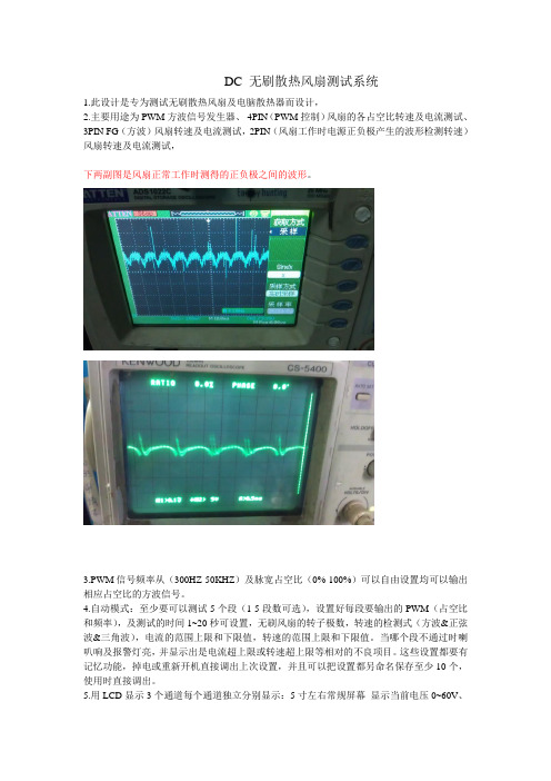
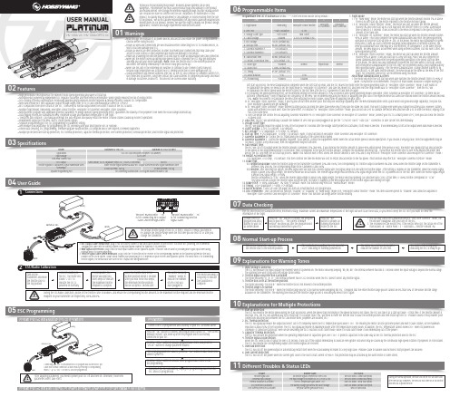
2.主要用途为PWM方波信号发生器、4PIN(PWM控制)风扇的各占空比转速及电流测试、3PIN FG(方波)风扇转速及电流测试,2PIN(风扇工作时电源正负极产生的波形检测转速)风扇转速及电流测试,
下两副图是风扇正常工作时测得的正负极之间的波形。
3.PWM信号频率从(300HZ-50KHZ)及脉宽占空比(0%-100%)可以自由设置均可以输出相应占空比的方波信号。
4.自动模式:至少要可以测试5个段(1-5段数可选),设置好每段要输出的PWM(占空比和频率),及测试的时间1~20秒可设置,无刷风扇的转子极数,转速的检测式(方波&正弦波&三角波),电流的范围上限和下限值,转速的范围上限和下限值。
当哪个段不通过时喇叭响及报警灯亮,并显示出是电流超上限或转速超上限等相对的不良项目。
这些设置都要有记忆功能,掉电或重新开机直接调出上次设置,并且可以把设置都另命名保存至少10个,使用时直接调出。
5.用LCD显示3个通道每个通道独立分别显示:5寸左右常规屏幕显示当前电压0~60V、
电流0~3A以上、功率、转速0~30000RPM(加大加粗字号重点显示)、占空比、测试结果及不良项目闪烁显示。
注意:一般频率变化4次=1RPM,RPM单位指的是转每分钟。
如针对4极转子风扇3000RPM=200HZ,6极定子风扇3000RPM=300HZ,8极定子风扇3000RPM=400HZ,
6.每测试完一个风扇后,再重新接上风扇系统会自动开始测试。
测试完毕LCD显示测试结果PASS&NG,并提示“请接下个产品”。
欧林-风机盘管无极调速(直流无刷)说明书

CERTIFICATE: CE RoHS WARRANTY: TWO YEARS精确度:±1℃ 温度设定范围:5℃-35℃ 功耗:<1W 风机输出控制:0~10VDC 输出 感温元件:NTC三、使用方法1.开、关机:通电状态下,请按开关键。
2.工作模式:请按模式键实现制冷、制热、手动(通风模式)等3种工作模式间的转换。
3.温度设定:请按加键或减键来调整温度;温度可设置为5-35℃。
4.风速设定:按设置键,可选择风速FAN1(超低), FAN2(低)、FAN3(中)、FAN4(高)、FAN5(超高)、FAN6(自动)。
当风速处于自动运行模式,如果“室内温度”与“设置温度”相差4℃以上时,风机将超高风速运行;如果相差3℃~4℃时,温控器选择风机高风速运行;如果相差2℃~3℃时,风机将中风速运行; 如果相差1℃~2℃时,风机将低风速运行; 如果相差0℃~1℃时,风机将超低风速运行;当室温与设置温度相同时,阀门关闭,同时风机关闭(风机是否受控可选择)。
5.菜单模式:按下模式切换键4秒,温控器进入菜单选择模式,连续按下模式切换键可以实现屏幕下侧数值在”1,2,3”之间转换:数值“1”--温度校正界面,按加键或减键调整温度校正值,默认值为0。
数值“2”--风机可控与不可控设置界面,C0代表风机可控,C1代表风机不可控。
按加键或减键,可实现CO 与C1间的切换;默认为C0。
数值”3”—机组型号和静压选择,首先按加键或减键选择机组型号,再按设置键转换选择静压。
注意:设定完毕等待5秒钟自动返回主界面。
风机输出电压设置方法按住设置键4秒以上,会自动跳出设置界面。
通过上下键调节电压输出,如显示的是555,表示实处电压为5.55VDC.然后按一下设置键松开,转换风机组合。
一共27个组合。
长按上下键,实现0.1步进的快速设置。
酷炫科技 DC 风扇温度控制器说明书

Purposes
The purpose of the device is to control the fan speed depending on the temperature. Any other use than specified in the manual is not allowed.
Installation
Connect the device according to the scheme. The device itself must be fastened to the metal, so that heat losses of the module can be easily dispersed. The connection does not need to be isolated, because there is no voltage drop on it.
无刷电动调速器用户手册说明书
0103Specifications04User Guide05ESC Programming06Programmable Items07Data CheckingProgrammable Item List of Platinum 60A V4 ESC. (“*” in the form below indicate factory defaults. )USER MANUALHV 130A V4 / HV 130A OPTO V4Brushless Electronic Speed Controller1. Flight Mode:1.1 In “Fixed-wing” mode, the motor will start up when the throttle amount reaches 5% or above. There is no soft start-up, the motor responds to the throttle increase rapidly.1.2 In “Helicopter (Linear Throttle)” mode, the motor will start up when the throttle amount reaches 5% and it will start up in a soft way with the throttle (from 0 to 100%) acceleration time is fixed to 3.5 seconds. It will accelerate to the RPM corresponds to the specific throttle amount at the fixed rate.1.3 In “Helicopter (Elf Governor)” mode, the motor will start up when the throttle amount reaches 40% or above. And it will complete the speed standardization and enter the speed-governing operation in the preset start-up time (4~25s). In this mode, the motor will standardize its speed every time it starts up. Due to different discharge rates/capabilities of different batteries, the RPM you standardize each time may be a little different. In consequence, at the same throttle amount, the RPM may be a bit different when using different batteries, but this won’t affect the speed-governing effect.1.4 In “Helicopter (Store Governor)” mode, the motor will start up when the throttle amount reaches 40% or above. It will also start up in a very soft way. And it will also complete the speed standardization and enter the speed-governing operation in the preset start-up time. In this mode, the motor will only standardize its speed the first time when it starts up. When performing RPM standardization for the first time, we recommend using a fully-charged battery with good discharge capability. After the RPM standardization, change another battery to fly your aircraft. At the same throttle amount, the RPM should be the same as the RPM of the first flight. For consistent control feel, we recommend using this mode. About RPM Standardization & OthersI. The motor will enter the soft start-up when user switches the throttle amount from 0 to 40% or above (50%throttle is recommended). The pitch of main blades should be 0 degree during the• High performance microprocessor for excellent motor speed-governing and super soft start-up.• Microprocessor powered by independent DC regulator has better anti-interference performance, which greatly reduces the risk of losing control.• DEO (Driving Efficiency Optimization) Technology adopted greatly improves throttle response & driving efficiency, reduces ESC temperature.• New switch-mode BEC with adjustable output voltage ranges from 5V to 8V and continuous/peak current of 10A/25A.• BEC is separated from other circuits of the ESC, it will keep its normal output when the MOSFET board of the ESC is burnt. • Multiple flight modes: Fixed-wing, Helicopter (Linear Throttle), Helicopter (Elf Governor),Helicopter (Store Governor).• New governor program with adjustable governor parameter P/I brings excellent speed-governing effect, guarantees the stability of the propeller’s revs when the load changes dramatically. • Data logging records the standardized RPM, minimum voltage and maximum temperature of the flight.• "Restart in auto rotation" can manually interrupt the auto rotation and quickly restart the motor to avoid crashes caused by incorrect operations. • Independent output port for RPM (that is: motor speed) signals.• Separate programming port for ESC programming or parameter setting.• WIFI module (sold separately) for programming the ESC wirelessly with your smart phone (IOS or Android).• Online data checking, ESC programming, firmware upgrade (Multifunction LCD program box or WIFI Express is needed) supported.• Multiple protections like start-up protection, ESC thermal protection, capacitor thermal protection, over-current protection, overload protection, and throttle signal loss protection.Model Applications Input Voltage Cont./Peak Current (10s)BEC OutputThrottle Signal/BEC Output/RPM Signal Transmission WiresSize/WeightSeparate Programming PortPlatinum HV 130A V4White Throttle Signal Wire/Red & Black BEC Output Wires/Yellow RPM Signal Transmission WireFor connecting Multifunction LCD Program Box/WIFI module or fanSwitch-mode, 5V-8V Adjustable (Step:0.1V), 10A/25A Cont./Peak101x45.5x27mm / 168.5gProgrammingConnect the LCD program box and a battery to your ESC as shown above.successfully connected to your ESC.relates to the ESC.main blades =R ÷ Motor Poles ÷ 2 ÷ Gear Ratio × Throttle Amount (%).channel on the VBAR system. About which channel you should plug it in, it depends on your receiver and flybarless system. The White wire is for transmitting Program Your ESC with a WIFI Express: For detailed information, please refer to the user manual of WIFI Express.The ESC will record the standardized RPM, minimum voltage, maximum current and maximum temperatures of the flight but won’t save these data, so you need to keep the ESC on if you want to check theinformation of the flight.08Normal Start-up ProcessTurn on the transmitter, and then move the throttle stick to the bottom position.After connected to a battery, the ESC will emit “♪123” indicating it’s normally powered on.The motor will emit several beeps to indicate the number of LiPo cells.The motor emits a long beep indicating the ESC is ready to go.09Explanations for Warning Tones1. Input voltage is abnormal:The ESC will measure the input voltage the moment when it’s powered on. The motor will keep beeping “BB, BB, BB” (the interval between two BBs is 1 second) when the input voltage is beyond the normal range. The warning tone won’t stop until the voltage turns normal. 2. Throttle signal loss protection is activated:The motor will beep “B-, B-, B-” (the interval between two B-s is 2 seconds) when the ESC doesn’t detect any throttle signal. 3. Throttle stick is not at the bottom position:The motor will beep “B-B-B-B-B-” when the throttle stick is not moved to the bottom position.4. Throttle range is to narrow:The motor will beep “B-B-B-B-B-” when the throttle range you set is too narrow (when designing this ESC, it requires that the entire throttle range you set cannot be less than 50% of the whole throttle range available on the transmitter.) The warning tone indicates the throttle range you set is void and you need to set it again.10Explanations for Multiple Protections11Different Troubles & Status LEDs1. Start-up Protection:The ESC will monitor the motor speed during the start-up process. When the speed stops increasing or the speed increase is not stable, the ESC will take it as a start-up failure. At that time, if the throttle amount is less than 15%, the ESC will automatically try to restart up; if it is larger than 15%, you need to move the throttle stick to back the bottom position and then restart up the ESC. (Possible causes of this problem: poor connection/ disconnection between the ESC and motor wires, propellers are blocked, etc.)2. ESC Thermal Protection:The ESC will gradually reduce the output but won’t cut it off completely when the ESC temperature goes above 110℃. For ensuring the motor can still get some power and won’t cause crashes, so the maximum reduction is about 50% of the full power. The ESC will gradually resume its maximum power after the temperature lowers down. In addition, the ESC temperature cannot exceed 70℃ when it’s powered on. Otherwise, it cannot be started up. (Here we are describing the ESC’s reaction in soft cutoff mode, while if in hard cutoff mode; it will immediately cut off the power.) 3. Capacitor Thermal Protection:The ESC will activate this protection when the operating temperature of capacitors goes over 130℃. It protects capacitors in the same way as the ESC thermal protection does to the ESC .4. Throttle Signal Loss Protection:When the ESC detects loss of signal for over 0.25 second, it will cut off the output immediately to avoid an even greater loss which may be caused by the continuous high-speed rotation of propellers or rotor blades. The ESC will resume the corresponding output after normal signals are received. 5. Overload Protection:The ESC will cut off the power/output or automatically restart itself when the load suddenly increases to a very high value. (Possible cause to sudden load increase is that propellers are blocked.)6. Over-current Protection:The ESC will cut off the power when the current gets close to the short circuit current (of 400A). This protection may be activated by the burnt motor or some others.soft start-up process, the RPM standardization completes when the soft start-up ends, and the ESC makes the motor enter the speed-governing state. In “Helicopter (Store Governor)” mode, if user wants to re-standardize the speed, he needs to set the flight mode to “Helicopter (Elf Governor)” and save this mode first, and then reset the flight mode back to “Helicopter (Store Governor)”, then the ESC will re-standardize the motor speed when the motor rotates for the first time after the ESC is powered off and then on again.II. For ensuring the speed-governing effect, we recommend setting the throttle amount to 85% or below in both speed-governing modes (Helicopter (Store Governor) & Helicopter (Elf Governor)), so there will besufficient compensating room to maintain the consistency of the RPM. We recommend replacing the motor or adjusting the gear ratio if the expected RPM still cannot be reached when the throttle amount exceeds 85%. (Note: You need to re-standardize the RPM after replacing the motor, blades, body frame or adjusting the gear ratio.)III. In “Helicopter (Store Governor)” mode, if you fly your aircraft with another pack that has poor discharge capability after the RPM standardization (with a pack which has good discharge capability), the pack has poor discharge capability will get damaged.IV. In “Helicopter (Store Governor)” mode, different battery packs can bring the same stable RPM only if they have the same cell count. This won’t change even when you change the battery pack. However, battery packs with different cell count don’t have the same effect. For instance, in “Helicopter (Store Governor)” mode, you can not use a 4S to calibrate the motor RPM and then use a 6S to drive the motor, hoping it can run at the same RPM.V. User can decide the control feel via adjusting Governor Parameter P/I. In “Helicopter (Store Governor) or Helicopter (Elf Governor)” mode, connect your ESC to a smart phone or PC, then you can check the throttle vs speed chart.2. LiPo Cells: The ESC will automatically calculate the number of LiPo cells you have plugged in as per the “3.7V/Cell” rule if “Auto Calc.” is selected. Or user can set this item manually. 3. Voltage Cutoff Type:The ESC will gradually reduce the output to 50% of the full power in 3 seconds after the voltage cutoff protection is activated, if soft mode is selected . It will immediately cut off all the output when hard mode is selected. 4. Cutoff Voltage: 2.8V-3.8V (custom), 3.0V (default).5. BEC Voltage: 5-8V (adjustable), 0.1V (step), 6V (default).6. Start-up Time: 4-25s (adjustable), 1s (step), 15s (default). (Note: It only functions in Helicopter (Store Governor) and Helicopter (Elf Governor))7. Governor Parameter P: Control the ESC maintaining the stability of the current motor speed.8. Governor Parameter I: Control the dynamic response. To be specific, control the supplement extent when the actual motor speed is below expectation. If you choose a very big value, then the supplement may be too much. If select a very small value, then the supplement may not sufficient.9. Auto Restart Time:the ESC will cut off its output when the throttle amount is between 25% and 40%. If you increase the throttle amount to above 40% within preset time period (0-90s), the motor will rapidly start up and accelerate to the speed (in the programmed Restart Acceleration Time) corresponds to the specific throttle amount, complete the shutdown and restart up . If you move the throttle stick to over 40% beyond the preset time period, the ESC will enter the soft start-up process. (Note: This function won’t effect unless the throttle amount is over 25% and it only effects in “Helicopter (Store Governor) and Helicopter (Elf Governor)” mode.)10. Restart Acceleration Time:1-3s (adjustable), 0.5s (step), 1.5s (default). This item controls the time the motor will cost to restart and accelerate to the full speed. (This function only effects in “Helicopter Governor Elf/Store” mode) 11. Brake Type:11.1 Proportional Brake: when the throttle range on the transmitter is between 20% and 100%, the corresponding ESC throttle output is between 0% and 100%.When the throttle range on the transmitter is between 20% and 0%, the corresponding brake force is between 0 and 100%.11.2 Reverse: after selecting this option, the RPM signal wire will turn into a reverse signal wire (the signal range is in line with the throttle range). After setting a channel on the transmitter, when the reverse signal length is above 20% signal length, the Reverse mode will be activated. The reverse signal length must be below 20% signal length when the ESC is powered on for the first time. When the reverse signal length is below 20% signal length, 0-100%throttle corresponds to “CW”; when the reverse signal length is above 20% signal length, the motor will stop spinning CW (and then spin CCW); at this time, 0-100% throttle corresponds to “CCW”. Any signal loss will activate the throttle signal loss protection, no matter it happens to the RPM signal wire or the throttle signal cable during the flight.12. Brake Force: 0-100% (adjustable), 1% (step), 0 (default). (Note: this function only effects in “Normal Brake” mode.)13. Timing: 0-30° (adjustable), 1° (step), 15° (default).14. Motor Rotation: CW/CCW. User can adjust this item via a multifunction LCD program box.15. DEO (Freewheel): User can decide this function “Enabled” or “Disabled” in “Fixed Wing” mode or in “Helicopter (Linear Throttle)” mode. This item has been preset to “Enabled” and cannot be adjusted in “Helicopter (Store Governor) and Helicopter (Elf Governor)” mode. This function can brings better throttle linearity.During the normal operation, the Blue LED on the ESC will turn solid after the start-up completes. The Red LED will come on at full throttle and dies out at partial throttle.。
无刷直流电机控制器使用说明书

1无刷直流电机控制器使用说明书
该控制器适用于直流12V/24V、功率200W 以下、转速30000转以内、电气相位为60°/120°的直流无刷电动机。
主要特点:
霍尔传感器解码、电子换相、适用于电气相位为60°/120°的无刷直流电机。
PWM 无级调速,调速范围为额定转速的10%-100%。
提供了开环和闭环两种速度检测方式。
控制方式:启动/停止、制动/运转、正转/反转。
保护功能:过流保护、欠压保护、短路保护、过热保护、电机堵转保护、传感器错相保护。
使用注意事项:
1、电源一定不能接反,否则会损坏电机控制器。
2、电机的各相及检测线必须和控制器正确连接,否则电机无法正常运转。
3、PR1为力度调节电位器,顺时针调节为力度增加,逆时针调节为力度减小;
PR2为速度调节电位器,顺时针调节为速度减小,逆时针调节为速度增加。
4、调节力度、速度电位器时,请用小一字螺丝刀微调多圈。
- 接直流电源正极 - 接直流电源
地 - 接电机绕组A (粗
白线)- 接电机绕组B (粗蓝线)- 接电机绕组C (
粗绿线)- 接红色线(细线) - 接黑色线(细线) - 接电机相位检测器A
(细白线) - 接电机相位检测器B (细蓝线) - 接电机相位检测器C
(细绿线
)
- 接地线(停止)、悬空(运- 未定义 - +15V 电源
- 接地线(正转
)
、
悬
空
(
反- 故障
输出-
地线
电源
指示灯 故障指示灯 - 地线- 接地线(运转)、悬空(制。
DC风扇输入输出特性说明-Forcecon

DC风扇输入输出特性说明:1. 额定电压:风扇正常运转所需要的固定电压.(伏特:Vdc)目前为5 Vdc, 12 Vdc, 24 Vdc, 48 Vdc2. 电压使用范围:风扇能正常运转的电压范围.为额定电压的±10% 3. 起动电压:规定一额定电压(低电压),插上电源让风扇通电检测是否运转.(伏特:Vdc)3.1 标准风扇或PWM控制风扇 6 Vdc .必须能运转3.2 特殊规格 4 Vdc .必须能运转注:依据风扇承认书内容为准.4. 额定电流:在风扇正常运转(额定电压条件下)时最高的电流.(安培:A)4.1须符合安规申请的最大电流以下.4.2若无安规机种:1.驱动IC Datasheet 内的最大承受电流以下.2.线圈温升.常温下不得超过80度.以额定电压的 + 10% 电压量测.5. 额定功率:在额定电压与额定电流下的功率.(瓦特:W)计算公式:W=I*V(功率=电流*电压)6. 转速:风扇转速自启动到稳定之时间,因轴承结构不同而有快慢,同一结构时又因厂商和温度高低而有差异.一般的判定标准时间如下:(25℃,65%)7. 运转方向:依据风扇扇叶的运转方向设计PCB Hall摆放位置(逆时针或顺时针方向).8. 风流方向:风扇运转时出风的方向.有第三条导线(大致为黄线)9.2. 高低电压形RD ( Alarm)用来输出讯号.表示风扇的状况(运转或停止). Vcc( 0.6V Max )VceRunning Locked rotor Auto Restart Running12.PWM控制功能测试:于风扇导线输入端,利用讯号产生器加入25KHZ之DUTY CYCLE讯号,使风扇依照输入之%数,改变风扇运转之转速.13.Soft Start 缓起动功能测试:利用示波器量测风扇插电后,测试其转速从零至最高转速之运转时间,是否有时间差显现,并要符合设计规范需求.14. 操作温度:标准为75℃~-10℃操作温度为风扇运转时的使用温度范围保存温度:标准为85℃~-20℃。
48VDC无刷数显驱动说明书

尊敬的用户:非常感谢您购买本公司生产的无刷直流电机驱动器,在使用本产品前请先认真阅读本说明书,谢谢!无刷直流电机驱动器是我公司重点研究开发的系列产品之一,它的功能更加完善,产品经过严格检测,质量可靠。
一、产品说明无刷直流电机驱动器是我公司自主研发的系列产品之一,该产品选用直流供电,适合驱动我公司开发的无刷直流电机,也适用于其他厂商和形式同规格的无刷直流电机,本产品采用DSP控制,调速比宽,接口功能较多,调速方式灵活,控制简单,保护功能完善可靠,最大限度地方便用户使用,适合绕线机、医疗设备、纺织设备等诸多场合。
二、性能特点★起停及转向控制★过流过载及堵转保护★测速信号输出★电机转速显示★外部模拟量调速★制动快速停机五、功能及使用说明1)调速方式本驱动器提供以下三种调速方式,用户可任选一种:内部电位器调速:逆时针旋转驱动器面板上的电位器,电机转速减小,顺时针则转速增大;由于测速需要响应时间,速度显示会有滞后;用户使用其他两种转速控制方式时必须将电位器设于最小状态。
外部输入调速:将外接电位器的两个固定端分别接于驱动器的“+5”和“地”端上,将调节端接于“A VI”上即可使用外接电位器调速,也可以通过其他的控制单元(如PLC、单片机等)输入模拟电平信号到“A VI”端实现调速(相对于COM),“A VI”的接受范围为DC0V~5V,对应电机转速为0~1000转/分;端子内接电阻10K到COM端,因此悬空不接将被解释为0输入。
电机运行/停止控制(R/S)通过端子“R/S”相对于地的通断可以控制电机的运行和停止,当“R/S”与端子地断开时电机运行,反之电机停止,使用“R/S”端控制电机停止时,电机为自然停车,其运动规律与负载惯性有关。
2)电机正反转控制通过控制端子“DIR”与端子“地”的通断可以控制电机的运行方向。
当“DIR”与端子“地”断开,电机顺时针旋转(面对电机轴),反之逆时针旋转,若电机在运行过程中方向信号改变,则电机会自然停止,等速度信号复位归零,重新启动才变方向运行。
基于单片机的无刷直流风扇转速测量与调节
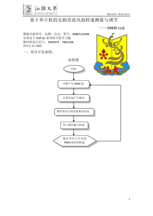
基于单片机的无刷直流风扇转速测量与调节——09ME-LLQ测量风扇型号:品牌:台达,型号:AFB0712HHB东流电子HOT 51系列单片机学习板数码管显示芯片:74HC573 74HC138使用C语言编程一、项目开发流程:流程图开始中断产生PWM波计算风扇产生脉冲数码管显示理论值和实际值串口通信输入转速输出对应占空比的PWM波控制转速二、源程序#include<reg52.h>#define uint unsigned int#define uchar unsigned char#define ulong unsigned longuchar code table[10]={0x3f,0x06,0x5b,0x4f,0x66,0x6d,0x7d,0x07,0x7f,0x6f}; //不带小数点数字uchar code LED_W[8] = {0,1,2,3,4,5,6,7}; //亮数码管位sbit d1=P1^0;ulong number;uint num,tta,ttc,bb,cc,pm;uchar i=0;void Delay(uint i) //用于显示数码管,软件廷时1ms{uchar x,j;for(j=0;j<i;j++)for(x=0;x<=148;x++);}void display(num) //显示程序{P0 = table[num/1000]; //显示转速测量值if((num/1000)!=0){P2 = LED_W[4];}Delay(1);P0 = table[(num/100)%10];P2 = LED_W[5];Delay(1);P0 = table[(num/10)%10];P2 = LED_W[6];Delay(1);P0 = table[num%10];P2 = LED_W[7];Delay(1);P0 = table[bb/1000]; //显示转速目标值if((bb/1000)!=0){ P2 = LED_W[0]; }Delay(1);P0 = table[(bb/100)%10];P2 = LED_W[1];Delay(1);P0 = table[(bb/10)%10];P2 = LED_W[2];Delay(1);P0 = table[bb%10];P2 = LED_W[3];Delay(1);}void Init(void) //程序初始化{EA=0;tta=0;num=0;bb=600;number=0;pm=800;TMOD = 0x26; //T0计数模式3,T1定时模式3 PCON = 0x00;SCON = 0x50;TH0=0xff; //计数器T0,一个脉冲溢出TL0=0xff;TH1 = 0xFd; //设置串口波特率9600TL1 = 0xFd;RCAP2H=(65536-50)/256; //定时器T2,定时0.5msRCAP2L=(65536-50)%256;ET0=1; //开T0、T1、T2中断允许ET2=1;TR0=1;TR1=1;TR2=1; //启动定时器1ES=1; //开串口中断EA=1; //开总中断}void pwm(bb) //调速程序{if(bb>=2100) pm=1910;else if(bb>=2000) pm=1835;else if(bb>=1900) pm=1650;else if(bb>=1800) pm=1500;else if(bb>=1700) pm=1370;else if(bb>=1600) pm=1240;else if(bb>=1500) pm=1150;else if(bb>=1400) pm=1110;else if(bb>=1300) pm=1030;else if(bb>=1200) pm=990;else if(bb>=1100) pm=905;else if(bb>=1000) pm=845;else if(bb>=900) pm=770;else if(bb>=800) pm=718;else if(bb>=700) pm=655;else if(bb>=600) pm=620;else if(bb>=500) pm=575;else if(bb>=400) pm=535;else if(bb>=300) pm=500;}void Main(void) //主函数{Init();while(1){if(num<bb-12) //速度微调pm=pm+1;else if(num>bb+12)pm=pm-1;elsepm=pm;display(num);}}void exter1() interrupt 1 using 1 // 定时器T0,P3.4接口计数方式{i++;number=number+tta;tta=0;if(i==3) //测量三次求平均值,减小转速波动{i=0;num=1800000/number;number=0;}}/* void Timer1 (void) interrupt 4 using 2 //T1,串口接收十六进制格式发送的目标转速{static uchar i=1; //定义为静态变量,当重新进入这个子函数时i的值不会发生改变EA = 0;if(RI == 1) //当硬件接收到一个数据时,RI会置位{if(i==1){cc=SBUF;RI=0;EA=1;}if(i==0){cc=cc*256+SBUF;RI=0;EA=1;i=2;bb=cc;cc=0;}i--;}pwm(bb);} */void Timer1 (void) interrupt 4 using 2 //T1,串口接收字符格式发送的目标转速{static uchar i=3; //定义为静态变量,当重新进入这个子函数时i的值不会发生改变EA = 0;if(RI == 1) //当硬件接收到一个数据时,RI会置位{if(i==3){cc=(SBUF-48);RI=0;EA=1;}if(i==2){cc=cc*10+(SBUF-48);RI=0;EA=1;}if(i==1){cc=cc*10+(SBUF-48);RI=0;EA=1;}if(i==0){cc=cc*10+(SBUF-48);RI=0;EA=1;i=4;bb=cc;cc=0;}i--;}pwm(bb);}void timer2() interrupt 5 using 3 //定时器T2,0.5ms中断产生PWM方波{static uchar i=0;TF2=0;i++;tta++;ttc++;if(ttc>=pm) //占空比0.22以下,风扇不转{d1=0;if(ttc==2000) //PWM波周期为100ms,周期越小,转速越稳定{d1=1;ttc=0;}}}。
- 1、下载文档前请自行甄别文档内容的完整性,平台不提供额外的编辑、内容补充、找答案等附加服务。
- 2、"仅部分预览"的文档,不可在线预览部分如存在完整性等问题,可反馈申请退款(可完整预览的文档不适用该条件!)。
- 3、如文档侵犯您的权益,请联系客服反馈,我们会尽快为您处理(人工客服工作时间:9:00-18:30)。
DC无刷风扇转速测试仪说明书(BK-820A)
一、产品特点
产品性能可靠,LCD点阵显示,体积小,很方便流水线生产使用
使用简单,只需将风扇连接到测试仪就可测试到转速,具有风扇极性反接,短路保护功能。
电流、电压、功率显示,可以单独做直流电源使用。
DC风扇测试:可测试2线、3线、4线和带FG、FD信号无刷风扇。
AC风扇测试:需单独配红外感应头测试,测试时不需要在风扇上做任何标号,可
以准确的测试转速。
PWM输出,分自动/手动控制,手动0-100%占空比可调,自动分四段,每段占的空比都可调,每段的间隔时间可以从1-99秒任意设置。
PWM输出电压可以选择5V或。
可设置转速最大和最小限值,超出限值喇叭报警。
可设置电流最大和最小限值,超出限值喇叭报警。
可以通过示波器连接到测试仪上BNC头方便测试电流波形。
测试方式分快速测试和平均值测试,用平均值测试方式可以测的更准。
二、技术参数
输入电压AC 170-230V
输出电压DC 0V-30V ±
输出电流0mA-20A ±
电流显示0mA-20A 电流小于30mA时只显示0mA
转速显示0-60000RPM 误差<±1%
风扇叶数0-24可调
PWM 占空比 0-100%占空比可调 输出频率25KHz
三、 结构介绍
四、 显示屏介绍 五、
使用
说
明 电源开电压调
微调 粗调 DC 无刷风扇转速测试仪 BK-820A
+ PWM PG - 输入
电压调开功能键 显示输入1 输入2
电压微。