config设置中文解释
config用法 -回复
config用法-回复"config用法"指的是在计算机编程中使用配置文件(config file)的方式来设置程序的参数和选项。
配置文件是一种文本文件,其中包含了程序运行所需的各种配置信息,比如数据库连接信息、日志输出级别、界面风格等。
在本文中,我将详细介绍config的使用方法,包括创建、读取、修改和删除配置文件,在不同的编程语言中,如Python和Java中的具体实现方法。
让我们一起来探索吧。
第一部分:创建配置文件首先我们需要了解配置文件的基本格式。
一般来说,配置文件采用键值对的形式,每个键值对都表示一个配置选项和它的值。
键和值之间使用等号或冒号进行分隔。
举个例子,我们可以创建一个名为config.txt的配置文件,内容如下:database.url = localhostdatabase.port = 3306ername = rootdatabase.password = secret这个配置文件定义了数据库连接信息,如地址、端口、用户名和密码等。
你可以根据自己的需要定义不同的配置选项。
第二部分:读取配置文件接下来,我们将学习如何在程序中读取配置文件的内容。
一种常见的方法是使用操作系统提供的文件读取函数,比如Java中的FileReader或Python中的open函数。
我们可以逐行读取配置文件,并将键值对存储在程序中的数据结构中,比如字典(Dictionary)或Properties对象。
在Python中,我们可以使用ConfigParser模块来读取配置文件。
首先,我们需要导入ConfigParser模块并创建一个ConfigParser对象,然后调用其read方法来读取配置文件。
以下是一个示例代码:pythonimport configparser# 创建ConfigParser对象config = configparser.ConfigParser()# 读取配置文件config.read('config.txt')# 获取特定配置选项的值db_url = config.get('database', 'url')db_port = config.getint('database', 'port')# 输出配置选项的值print(db_url)print(db_port)在上面的示例中,我们使用`get`方法获取了数据库地址和端口的值,并使用`getint`方法将端口的值转换为整数类型。
关于config的配置文件
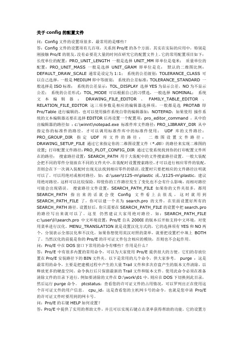
关于config的配置文件问:Config文件的设置项很多,最常用的是哪些?答:Config文件的设置项有几百项,关系到Pro/E的各个方面。
其实在实际的应用中,特别是刚接触Pro/E的朋友,没有必要花大量的时间在研究它的配置文件上。
它的常用配置项目如下:长度单位的配置:PRO_UNIT_LENGT H 一般是选择UNIT_MM即单位是毫米;质量单位的配置:PRO_UNIT_MASS 一般是选择UNIT_GRAM即单位是克;默认的二维图比例:DEFAULT_DRAW_SCALE 通常是设定为1:1;系统的公差级别:TOLERANCE_CLASS 可以自己选择,一般是MEDIUM即中等级别;系统的公差标准:TOLERANCE_STANDARD 一般选择是ISO标准;系统的公差显示:TOL_DISPLAY 选择YES为显示公差,NO为不显示公差;系统的公差形式:TOL_MODE 可以根据自己的习惯选,一般选择NOMINAL;系统文本编辑器:DRAWING_FILE_EDITOR、FAMILY_TABLE_EDITOR、RELATION_FILE_EDITOR这三项参数是相应的编辑器选择项,一般都是选PROTAB即Pro/Table进行编辑的,也可以使用操作系统自带的编辑器如:NOTEPAD;如果使用操作系统的文本编辑器还要在选择EDITOR后再设置一个配置项:pro_editor_command ,从中给出编辑器的路径如:c:\winnt\notepad.exe 标准件库文件路径:PRO_LIBRARY_DIR 从中指定你的标准件的路径,才可以调用标准件库中的标准件使用;UDF库的文件路径:PRO_GROUP_DIR 指定UDF库文件的路径;二维图设置文件路径:DRAWING_SETUP_FILE 通过它来指定你的二维图设置文件(*.dtl)的路径来实现二维图的设置; 打印配置文件路径:PRO_PLOT_CONFIG_DIR 通过它使系统找到你的打印配置文件所在的路径;搜索路径设置:SEARCH_PATH 用于大装配中的文件搜索路径设置。
midas 调音台中英对照表

M32面板中英文对照表1、CONFIG/PREAMP:配置/前置放大2、Home :首页3、GAIN :前置放大器4、Meters :音量输出栏5、FREQUENCY :频率6、ROUTING :路由配比7、VIEW :视图8、EFFECTS :效果器9、GATE :门10、MUTE GRP:静音编组11、THresh :阈值12、UTILITY :通用程序13、Dymanica :动态压缩14、MONITOR :监听15、EQUALISER :均衡16、MONITOR LEVEL:监听音量17、WIDTH :宽度18、STEUP :设置19、HIGH :高频20、LIBRARY :预设21、HI MID:中高频22、Phones LEVEL:话筒音量23、LO MID:中低频24、DIM :监听内部放大25、LOW :低频26、TALK BACK:对讲话筒27、MODE :模式28、EXT MIC:话筒插口29、HCUT :高切30、TALK LEVEL:话筒音量31、HSHV :水平增加,衰减32、TALK A:话筒A 33、PEQ :Q 值大小34、TALK B:话筒 B 35、LSGV :水平增加衰减36、DAW REMORE:声卡配比37、LCUT :低切38、SEL :锁定39、BUS SENDS:总线输出40、SOLO :单独41、RWCORDER :录音机42、INPORT :输入43、ACCESS :访问44、AUX IN:辅线输出45、MAIN BUS:总线46、BUS MAST:总线输出47、M/C LEVEL:单声道/中置音量48、FADER MAINC:推子组设置49、PAN/BAL:声向50、GROUP DCA:编组51、MONO CENTRE:单声道52、BUS :总线53、MAIN STEREO:主立体声54、MTX MAINC:输出阻拦55、SHOW CONTRL:线视控件56、LAST :上一个57、NEXT :下一个58、UNDO :撤销59、ASSIGN :分配60、SET :集合M32系统界面中英文对照表HOME 键一、Home :1、IN :进2、48:48伏供电3、Φ:4、Delay :延时5、Locat :低切6、Link :线路输入7、Gain :增益8、Gate :噪声门9、Thersh :阈值10、E Q:均衡11、Dymanica :动态压缩12、Comp :压缩比13、INS :直进直出14、OUT :出15、MONO :单声道16、MUTE :静音17、L R:左右总输出19、SAFE :安全模式20、DCA :编组模式21、MUTE GROUP:静音编组22、POST :在、、、之后23、COMD EXP:24、CHANNEL :通道25、ASSIGN :分配26、Fader :推子二、config :配置1、input Level:输出电平2、LINK :线路输入3、LO CUT:低切4、DELAY :延时5、INSERT :直进直出6、LINK :线路输入7、LO CUT:低切8、SOURCE :源9、INS POS:插入点10、CONNECT :链接三、gate :噪声门1、RANGE :范围2、ATTACK :开启时间3、HOLD :持续时间4、RELEASE :恢复时间5、KEY FILTER:滤波器6、FRAQ :阈值7、SLOPE/Q:Q 值8、THEWSHOLD :9、MODE :模式10、ATTACK :开启时间11、HOLD :持续时间12、RELEASE :恢复时间13、RANGE :范围14、ACTIVE :15、KEY SOURCE:信号来源16、FILT FREQ:滤波频率17、SELECT :选择18、KEY SOLO:独奏四、dyn :限幅1、RATIO :比值2、KNEE :拐点3、ATTACK :开启时间4、MIX :混合5、COMP :压缩器6、EXP :口7、PEAK :峰值8、RMS :比值9、LIN :锁定10、LOG :退出11、AUTO :12、PRO EQ:EQ 前五、EQ :均衡1、LOW CUT:低切2、LOW :低频3、LOW MID:中低频4、HIGH MID:中高频5、HIGH :高频6、FREQ :频率7、MODE :模式8、BAR :9、SPEC :规格10、RTA PRE:预设置11、RESTE :选择12、RESTE ALL:全部选择六、SENDS :发送1、POST FADER:推子后2、IN\LC:插入点3、PRO EQ:EQ 前4、POST EQ:EQ 后5、PRO :在,,, 之前6、SCROLL :从上到下移动7、JUMP+4:8、MODE1\2:七、MAIN :主输出1、LR+MONO:左右+单声道2、LCR :左中右3、LEFT :左4、MONO :单声道5、RIGHT :右6、MONO LVI:单声道METERS 键一、CHANNEL :通道1、INPUT CHANNEL:输入通道2、GAIN REDUCTION GATE:增益降低门3、GAIN REDUCTION DYN:增益衰减动力学三、AUX\FX:辅线\效果二、MIX BUS:混合总线1、MATRIX :矩阵2、MAIN BUS:主要的总线3、M\C:1、AUX SENDS:辅线输出2、AUX RETURNS:辅线返回3、ST FX RETURNS:总线效果返回四、IN\OUT:进\出1、INPUTS :输入2、AES\EBU:3、MONITOR :监控4、P16 UITRANET OUYPUTS:五、RTA :1、PRE EQ:预均衡2、SPECTROGRAPH :摄谱仪3、USE RTA SOURCE:使用RTA 源4、POST GEQ:均衡后5、SOLO PRIORITY:优先6、SELECTED CH:选择通道7、MONITOR :监控8、PEAK HOLD:峰值保持9、BAR :10、SPEC :规格11、DECAY :衰减12、PEAK :峰值13、RMS :表14、AUTO GAIN:自动增益15、EQ OVERTAY:均衡叠加16、PRE :在,,,之前17、SOURCE :信号18、SET :集ROUTING 键一、HOME :菜单1、CHANNEL PROCESSING BIOCK PATCH :通道处理2、INPUTS 1-8:输入1-83、INPUTS 9-16:输入6-164、INPUTS 17-24:输入17-245、INPUTS 25-32:输入25-326、AUX IN REMAP:辅线映射7、AES50 A:8、AES50 B:9、CONNECTED DEVICES:链接的设备10、CONNECT :链接一、AUX 1-161、ANALOG OUTPUT:模拟输出2、EDIT OUTPUT ASSIGNMENT:输出分配3、CURRENT SETTING:当前设置4、MAIN L:主要5、POST FADER:推子后6、CATEGORY :类别7、DIRECT OUT:直接输出8、OUTPUT SIGNAL:输出信号9、TAP :阀门10、IN\LC:插入11、PRE EQ:EQ 之前12、POST EQ:EQ 之后13、PRE FDR:推子之前二、AUX OUT :辅线输出三、P16 OUT1、DIROUT CH 01:2、IQ SPEAKER:扬声器3、NONE :没有4、LIVE :音量大小5、SPEECH :演讲6、PLAY BACK:播放7、USER :用户8、MODEL :模式9、SPERKER GROUP:编组四、CARD OUT:1、EXPANSION CARD OUTPUTS 1-8:扩展卡的输出1-82、EXTERNAL CONNECTION STATUS:外部的连接状态五、AES50-A :六、AES50-B :七、XIR OUT:SETUP 键一、GLOBAL :全球1、FIRMWARE :固件2、SYSTEM CONTROL:系统控制3、SHUT DOWN:关闭4、REBOOT :重新启动5、UPDATE FW:更新固件6、SAMPLE RATE:采样率7、SYNCHRONIZATION :同步8、INITIALIZATION :初始化9、CONSOLE :操控台10、SHOW DATA:数据显示11、LIBRARIES :图书馆12、FACTORY RST:原厂设置13、TIME\DATA:时间数据14、MAIN LCD BRIGHTNESS:主屏亮度15、LED BRIGHTNESS:LED 亮度16、CHANNEL LCD CONTRAST:通道液晶17、BRIGHE :亮度一、CONFIG :配置1、CONFIRM POP-UPS:确认pop-ups2、GENERAL :一般3、OVERWRITE :覆盖4、SCENE LOAD:现场负荷5、GENERAL PREFS:一般参数6、SCENE GO NEXT:下一个场景7、SAFE MAIN LEVEIS:推子保护8、12G CLOCK MODE:12G 时钟模式9、SHOW CONTROL:显示控制10、CUES :线索11、SCENES :场景12、SNIPPETS :片段13、VIEW PREFERENCES:个人偏好14、RETURN TO LAST:回到上级15、SEF FOLLOWS BANK:16、AUTO SELECT:自动选择17、MUTE SYSTEM:静音系统18、HARD MUTES:强制静音19、DCA GUOUPS:DCA 编组20、INVERT LEDS:转化LED21、LINK PREFERENCES:输入的偏好22、DELAY+HALINK:延时+ 23、EQLINK :EQ 输入24、DYNAMICS LINK :压缩输入25、MUTE\FADER LINK :静音\推子输入26、M\C DEPENDS ON MAIN L\R:27、PANNING MODE:全景模式28、LR+MONO:左右+中置29、LCR+ENABLE:30、BUS PRE-CONFIGURATION:BUS 输出配置三、REMOTE :远程1、REMOTE SECTION:远程部分2、REMOTE BUTTON:遥控按钮3、ENADLE :4、REMOTE PROTOCOL:远程协议5、MACKIE MCU:6、MACKIE HUI:7、GENETIC CC:8、REMOTE INTERFACE:远程接口9、MIDI IN\OUT:10、CARD MIDI:11、RTP MIDI:12、MIDI CONTROL INTERFACE:13、MIDI RECELVE:14、PEOG CHANGE:15、FADER POS CC:16、CH MUTE CC:17、CH PAN CC:18、MIDI TRANSMIT:19、MIDI SYSTEM EXCLUSIVE:20、OSC OVER MIDI SYSEX:四、NETWORK :网络1、IP ADDRESS:IP 地址2、SUBNET MASK:子网掩码3、GATEWAY :网关五、SCRIBBLE STRIP:自定义1、CHANNEL :通道2、COLOR :颜色3、LCON :图标4、SNIPPETS :片段5、NAME :名字六、PREAMPS :前置放大器1、PREAMP BLOCKS:前置放大器模块2、PREAMP CONTROLS:前置放大器控制3、SELECTED DEVICS:选择器件4、GLOBAL OPTIONS:全局选项5、LOCK STAGEBOX:锁定6、HA GAIN SPLIT:增益分裂7、HA REMOTE:遥控8、AES50 PORT A aes50协议A 口9、AES50 PORT B aes50协议b 口七、CARD :1、DN32-USB 32IN\32OUT USB CARD:录音信号32进32出2、CONFIGURATION :配置LIBRARY 键一、CHANNEL :通道1、RECALL SCOPE:召回范围2、HEAD AMP:前置放大器3、CONFIGURATION :配置4、GATE :门5、COMPRESSOR :压缩6、EQUALIZER :均衡器7、SENDS\MAIN:发送\主8、PRESET LIBRARY:预置库一、EFFECTS :效果1、SELECT FX SLOT:选择FX 槽2、EFFECT 1:效果1通道3、VINTAGE ROOM:老式的房间4、BIG CONCERT:大型演唱会5、VOCAL PLATE:发声板6、CATHEDRAL :大教堂7、ECHO HANGAR:回声库8、DRUM TREAT:老式的混响9、SOUND STAGE:舞台音响10、PHIL ’S DRUMS:11、ACK WATDS:12、MEMORY MAN:立体声延迟13、THIRD GEOOVE:14、CANYON :峡谷15、DANISH CHOR:立体声合唱一、ROUTING :路由1、RECALL PATCHING SCOPE:2、CHANNEL IN:通道3、ANAIOG OUT:模拟输出4、AUX OUT:辅线输出5、P16 OUT:p16输出6、CARD OUT:声卡输出7、AES50 OUT:aes50协议输出8、XLR OUT:主输出EFFECTS 键一、HOME :菜单1、FX1-4(SIFE-CHAIN\INSERT) :FX1-42、FX5-8(INSERT) :FX5-8插入MUTE GRP键1、MUTE GROUP:静音编组UTILITY 键一、PRESET :预设1、RECALL SCOPE:召回范围2、HEAD AMP:前置放大器3、CONFIGURATION :配置4、GATE :门5、COMPRESSOR :压缩6、EQUALIZER :均衡器7、SENDS\MAIN:发送\主8、SCROLL :从上到下移动9、LOAD PRESET:载入预设10、SAVE PRESET:保存预置11、DELETE :删除12、COPY :复制13、PASTE :粘贴MONITOR 键一、MINITOR :监测1、SOLO OPTIONS:监听选项2、EXCLUSIVE(LAST) :单独3、SOLO FOLLOWS SELECT:监听如下选择4、SELECT FOLLOWS SOLO:选择如下监听5、CHANNEL SOLO AFL:通道监听6、MIXBUS SOLO AFL:总线监听7、DCA SOLO AFL:编组监听8、USE DIM FOR PFL:放大电路预监听9、USE MASTER FADER:主音量调节10、MID ATTEN:11、SOURCE :信号源二、TALKBACK A:对讲A1、TALK SIGNAL A\B:通话信号2、TALKBACK A\B:对讲3、ENABLE :使用4、ENABLE TALKBACK:使用对讲5、TALK DESTINATION A:通话目的地6、MONITOR DIM MODE A:监控待机模式7、AUTO :自动8、BUTTON MODE A:按键模式9、LATCH :门闩10、LAMP DIM:11、LAMP :灯12、12V DC:12v 自流电三、TALKBACK B:对讲B四、OSCILLATOR :振荡器1、TONE :音2、FREQUENCY :频率3、OSCILLATOR TYPE:振荡器类型4、SINE WAVE:正弦波5、PINK NOISE:粉红噪声6、WHITE NOISE:白噪声7、DESTINATION :目的地8、GENERATE :生成9、FREQ :频率。
midas 调音台中英对照表

1、 CONFIG/PREAMP:配置/前置放大2、 Home :首页3、 GAIN :前置放大器4、 Meters :音量输出栏5、 FREQUENCY :频率6、 ROUTING :路由配比7、 VIEW :视图8、 EFFECTS :效果器9、 GATE :门 10、MUTE GRP:静音编组 11、THresh :阈值 12、UTILITY :通用程序13、Dymanica :动态压缩 14、MONITOR :监听 15、EQUALISER :均衡 16、MONITOR LEVEL:监听音量 17、WIDTH :宽度 18、STEUP :设置 19、HIGH :高频 20、LIBRARY :预设 21、HI MID:中高频 22、Phones LEVEL:话筒音量 23、LO MID:中低频 24、DIM :监听内部放大 25、LOW :低频 26、TALK BACK:对讲话筒 27、MODE :模式 28、EXT MIC:话筒插口 29、HCUT :高切 30、TALK LEVEL:话筒音量 31、HSHV :水平增加,衰减 32、TALK A:话筒A 33、PEQ :Q 值大小 34、TALK B:话筒 B 35、LSGV :水平增加衰减 36、DAW REMORE:声卡配比 37、LCUT :低切 38、SEL :锁定 39、BUS SENDS:总线输出 40、SOLO :单独 41、RWCORDER :录音机 42、INPORT :输入 43、ACCESS :访问 44、AUX IN:辅线输出 45、MAIN BUS:总线 46、BUS MAST:总线输出 47、M/C LEVEL:单声道/中置音量 48、FADER MAINC:推子组设置 49、PAN/BAL:声向 50、GROUP DCA:编组 51、MONO CENTRE:单声道 52、BUS :总线 53、MAIN STEREO:主立体声 54、MTX MAINC:输出阻拦 55、SHOW CONTRL:线视控件 56、LAST :上一个 57、NEXT :下一个 58、UNDO :撤销 59、ASSIGN :分配 60、SET :集合M32系统界面中英文对照表HOME 键一、Home : 1、IN :进 2、48:48伏供电 3、Φ: 4、Delay :延时 5、Locat :低切 6、Link :线路输入 7、Gain :增益 8、Gate :噪声门 9、Thersh :阈值 10、E Q:均衡 11、Dymanica :动态压缩 12、Comp :压缩比 13、INS :直进直出 14、OUT :出 15、MONO :单声道 16、MUTE :静音 17、L R:左右总输出 19、SAFE :安全模式 20、DCA :编组模式 21、MUTE GROUP:静音编组 22、POST :在、、、之后 23、COMD EXP: 24、CHANNEL :通道 25、ASSIGN :分配 26、Fader :推子二、config :配置1、input Level:输出电平2、LINK :线路输入3、LO CUT:低切4、DELAY :延时5、INSERT :直进直出6、LINK :线路输入7、LO CUT:低切8、SOURCE :源9、INS POS:插入点 10、CONNECT :链接三、gate :噪声门 1、RANGE :范围2、ATTACK :开启时间3、HOLD :持续时间4、RELEASE :恢复时间5、KEY FILTER:滤波器6、FRAQ :阈值7、SLOPE/Q:Q 值8、THEWSHOLD :9、MODE :模式 10、ATTACK :开启时间 11、HOLD :持续时间 12、RELEASE :恢复时间 13、RANGE :范围 14、ACTIVE :15、KEY SOURCE:信号来源 16、FILT FREQ:滤波频率 17、SELECT :选择 18、KEY SOLO:独奏四、dyn :限幅1、RATIO :比值2、KNEE :拐点3、ATTACK :开启时间4、MIX :混合5、COMP :压缩器6、EXP :口7、PEAK :峰值 8、RMS :比值 9、LIN :锁定 10、LOG :退出 11、AUTO : 12、PRO EQ:EQ 前五、EQ :均衡1、LOW CUT:低切2、LOW :低频3、LOW MID:中低频4、HIGH MID:中高频5、HIGH :高频6、FREQ :频率7、MODE :模式 8、BAR :9、SPEC :规格10、RTA PRE:预设置 11、RESTE :选择12、RESTE ALL:全部选择六、SENDS :发送1、POST FADER:推子后2、IN\LC:插入点3、PRO EQ:EQ 前4、POST EQ:EQ 后5、PRO :在,,, 之前6、SCROLL :从上到下移动7、JUMP+4:8、MODE1\2:七、MAIN :主输出1、LR+MONO:左右+单声道2、LCR :左中右3、LEFT :左4、MONO :单声道5、RIGHT :右6、MONO LVI:单声道METERS 键一、CHANNEL :通道1、INPUT CHANNEL:输入通道2、GAIN REDUCTION GATE:增益降低门3、GAIN REDUCTION DYN:增益衰减动力学三、AUX\FX:辅线\效果二、MIX BUS:混合总线 1、MATRIX :矩阵2、MAIN BUS:主要的总线3、M\C: 1、AUX SENDS:辅线输出 2、AUX RETURNS:辅线返回3、ST FX RETURNS:总线效果返回四、IN\OUT:进\出 1、INPUTS :输入 2、AES\EBU:3、MONITOR :监控4、P16 UITRANET OUYPUTS:五、RTA :1、PRE EQ:预均衡2、SPECTROGRAPH :摄谱仪3、USE RTA SOURCE:使用RTA 源4、POST GEQ:均衡后5、SOLO PRIORITY:优先6、SELECTED CH:选择通道7、MONITOR :监控8、PEAK HOLD:峰值保持 9、BAR : 10、SPEC :规格 11、DECAY :衰减 12、PEAK :峰值 13、RMS :表14、AUTO GAIN:自动增益 15、EQ OVERTAY:均衡叠加 16、PRE :在,,,之前 17、SOURCE :信号 18、SET :集ROUTING 键一、HOME :菜单1、CHANNEL PROCESSING BIOCK PATCH :通道处理2、INPUTS 1-8:输入1-83、INPUTS 9-16:输入6-164、INPUTS 17-24:输入17-245、INPUTS 25-32:输入25-326、AUX IN REMAP:辅线映射7、AES50 A:8、AES50 B:9、 CONNECTED DEVICES:链接的设备 10、CONNECT :链接一、AUX 1-161、ANALOG OUTPUT:模拟输出2、EDIT OUTPUT ASSIGNMENT:输出分配3、CURRENT SETTING:当前设置4、MAIN L:主要5、POST FADER:推子后6、CATEGORY :类别7、DIRECT OUT:直接输出8、OUTPUT SIGNAL:输出信号9、TAP :阀门 10、IN\LC:插入 11、PRE EQ:EQ 之前 12、POST EQ:EQ 之后 13、PRE FDR:推子之前二、AUX OUT :辅线输出三、P16 OUT1、DIROUT CH 01:2、IQ SPEAKER:扬声器3、NONE :没有4、LIVE :音量大小5、SPEECH :演讲6、PLAY BACK:播放7、USER :用户8、MODEL :模式9、SPERKER GROUP:编组四、CARD OUT:1、EXPANSION CARD OUTPUTS 1-8:扩展卡的输出1-82、EXTERNAL CONNECTION STATUS:外部的连接状态五、AES50-A :六、AES50-B :七、XIR OUT:SETUP 键一、GLOBAL :全球 1、FIRMWARE :固件2、SYSTEM CONTROL:系统控制3、SHUT DOWN:关闭4、REBOOT :重新启动5、UPDATE FW:更新固件6、SAMPLE RATE:采样率7、SYNCHRONIZATION :同步8、INITIALIZATION :初始化9、CONSOLE :操控台 10、SHOW DATA:数据显示 11、LIBRARIES :图书馆12、FACTORY RST:原厂设置 13、TIME\DATA:时间数据14、MAIN LCD BRIGHTNESS:主屏亮度 15、LED BRIGHTNESS:LED 亮度16、CHANNEL LCD CONTRAST:通道液晶 17、BRIGHE :亮度一、 CONFIG :配置1、CONFIRM POP-UPS:确认pop-ups2、GENERAL :一般3、OVERWRITE :覆盖4、SCENE LOAD:现场负荷5、GENERAL PREFS:一般参数6、SCENE GO NEXT:下一个场景7、SAFE MAIN LEVEIS:推子保护8、12G CLOCK MODE:12G 时钟模式9、SHOW CONTROL:显示控制10、CUES :线索 11、SCENES :场景 12、SNIPPETS :片段13、VIEW PREFERENCES:个人偏好 14、RETURN TO LAST:回到上级 15、SEF FOLLOWS BANK:16、AUTO SELECT:自动选择17、MUTE SYSTEM:静音系统 18、HARD MUTES:强制静音 19、DCA GUOUPS:DCA 编组 20、INVERT LEDS:转化LED21、LINK PREFERENCES:输入的偏好 22、DELAY+HALINK:延时+ 23、EQ LINK :EQ 输入24、DYNAMICS LINK :压缩输入25、MUTE\FADER LINK :静音\推子输入 26、M\C DEPENDS ON MAIN L\R: 27、PANNING MODE:全景模式 28、LR+MONO:左右+中置 29、LCR+ENABLE:30、BUS PRE-CONFIGURATION:BUS 输出配置三、REMOTE :远程1、REMOTE SECTION:远程部分2、REMOTE BUTTON:遥控按钮3、ENADLE :4、REMOTE PROTOCOL:远程协议5、MACKIE MCU:6、MACKIE HUI:7、GENETIC CC:8、REMOTE INTERFACE:远程接口 9、MIDI IN\OUT: 10、CARD MIDI: 11、RTP MIDI:12、MIDI CONTROL INTERFACE: 13、MIDI RECELVE: 14、PEOG CHANGE: 15、FADER POS CC:16、CH MUTE CC: 17、CH PAN CC:18、MIDI TRANSMIT:19、MIDI SYSTEM EXCLUSIVE: 20、OSC OVER MIDI SYSEX:四、NETWORK :网络 1、IP ADDRESS:IP 地址2、SUBNET MASK:子网掩码3、GATEWAY :网关五、SCRIBBLE STRIP:自定义 1、CHANNEL :通道 2、COLOR :颜色 3、LCON :图标 4、SNIPPETS :片段 5、NAME :名字六、PREAMPS :前置放大器1、PREAMP BLOCKS:前置放大器模块2、PREAMP CONTROLS:前置放大器控制3、SELECTED DEVICS:选择器件4、GLOBAL OPTIONS:全局选项5、LOCK STAGEBOX:锁定6、HA GAIN SPLIT:增益分裂7、HA REMOTE:遥控8、AES50 PORT A aes50协议A 口9、AES50 PORT B aes50协议b 口七、CARD :1、DN32-USB 32IN\32OUT USB CARD:录音信号32进32出2、CONFIGURATION :配置LIBRARY 键一、CHANNEL :通道1、RECALL SCOPE:召回范围2、HEAD AMP:前置放大器3、CONFIGURATION :配置4、GATE :门5、COMPRESSOR :压缩6、EQUALIZER :均衡器7、SENDS\MAIN:发送\主8、 PRESET LIBRARY:预置库一、EFFECTS :效果1、SELECT FX SLOT:选择FX 槽2、EFFECT 1:效果1通道3、VINTAGE ROOM:老式的房间4、BIG CONCERT:大型演唱会5、VOCAL PLATE:发声板6、CATHEDRAL :大教堂7、ECHO HANGAR:回声库8、DRUM TREAT:老式的混响9、 SOUND STAGE:舞台音响 10、PHIL ’S DRUMS: 11、ACK WATDS:12、MEMORY MAN:立体声延迟 13、THIRD GEOOVE: 14、CANYON :峡谷15、DANISH CHOR:立体声合唱一、ROUTING :路由1、RECALL PATCHING SCOPE:2、CHANNEL IN:通道3、ANAIOG OUT:模拟输出4、AUX OUT:辅线输出5、P16 OUT:p16输出6、CARD OUT:声卡输出7、AES50 OUT:aes50协议输出 8、XLR OUT:主输出EFFECTS 键一、HOME :菜单1、FX1-4(SIFE-CHAIN\INSERT) :FX1-42、FX5-8(INSERT) :FX5-8插入MUTE GRP键1、 MUTE GROUP:静音编组UTILITY 键一、PRESET :预设1、RECALL SCOPE:召回范围2、HEAD AMP:前置放大器3、CONFIGURATION :配置4、GATE :门5、COMPRESSOR :压缩6、EQUALIZER :均衡器7、SENDS\MAIN:发送\主8、SCROLL :从上到下移动 9、LOAD PRESET:载入预设 10、SAVE PRESET:保存预置 11、DELETE :删除 12、COPY :复制 13、PASTE :粘贴MONITOR 键一、MINITOR :监测1、SOLO OPTIONS:监听选项2、EXCLUSIVE(LAST) :单独3、SOLO FOLLOWS SELECT:监听如下选择4、SELECT FOLLOWS SOLO:选择如下监听5、CHANNEL SOLO AFL:通道监听6、MIXBUS SOLO AFL:总线监听7、DCA SOLO AFL:编组监听8、USE DIM FOR PFL:放大电路预监听 9、 USE MASTER FADER:主音量调节 10、MID ATTEN:11、SOURCE :信号源二、TALKBACK A:对讲A1、TALK SIGNAL A\B:通话信号2、TALKBACK A\B:对讲3、ENABLE :使用4、ENABLE TALKBACK:使用对讲5、TALK DESTINATION A:通话目的地6、MONITOR DIM MODE A:监控待机模式7、AUTO :自动8、 BUTTON MODE A:按键模式 9、LATCH :门闩 10、LAMP DIM: 11、LAMP :灯12、12V DC:12v 自流电三、TALKBACK B:对讲B四、OSCILLATOR :振荡器 1、TONE :音2、FREQUENCY :频率3、OSCILLATOR TYPE:振荡器类型4、SINE WAVE:正弦波5、PINK NOISE:粉红噪声6、WHITE NOISE:白噪声7、DESTINATION :目的地8、GENERATE :生成9、FREQ :频率。
ProE系统配置config解释

Pro/Engineer Config.Pro & .DTL 配置文件环境变量说明Pro/E环境变量是用来设置Pro/E的工作环境的,你可以在config.pro文件里进行设置。
您可以按开头字母查找。
A B C D E F G H I K L M N O P Q R S T U V W XThis document contains a list of configuration options, in alphabetical order, showing for each option or group of related options:•Configuration option name.•Associated variables or values. The default values for the options are shown in italics. •Product type for which the option is used, if the option is specific to one type (for example, Layout, Assembly, Part, Drawing, and so on).•Brief description.accuracy_lower_boundvalue (between 1.0e-6 and 1.0e-4)Enter an accuracy value to override the default lower limit of 0.0001. The upper limit is fixed at 0.01.add_weld_mpyes, no•“yes”—the system includes welds when calculating mass properties.•“no”—the system excludes welds when calculating mass propertiesallow_confirm_windowyes, noDisplay a confirmation window when exiting Pro/ENGINEER. This enables you to use the mouse to confirm/cancel exiting Pro/ENGINEER.allow_move_view_with_moveyes, noWhen set to “yes,”allows the Move command in Drawing mode to move drawing views. allow_cycle_optimizeyes, noPrior to Release 18.0, there was a sequence parameter for holemaking that allowed users to optimize the cycle output to CL-data of holemaking sequences. This parameter has not been available since Release 18.0.•yes—makes the parameter visible in the sequence•no—the parameter is not visible in the sequenceallow_mod_attach_draft_dimyes, no•"no"—A #Detail, #Mod Attach is obsolete for draft feature dimensions; use #Detail, #Move to move the placement of the dimension along the same edge.•"yes"—When performing a #Detail, #Mod Attach to a draft feature dimension, you can select a different edge of the same feature to which to attach the dimension. The available edges for selection highlight in magenta.allow_move_attach_in_dtl_moveyes, noDetermines if the Move and Move Attach commands in drawing mode act together (yes) or not (no).allow_old_style_roundyes, noDetermines which round-creation functionality the system uses.•“yes”—Uses old (Release 16.0) functionality.•“no”—Uses new functionality.allow_ply_cross_sectionyes, no“yes”—Enables Pro/COMPOSITE to create a cross-section of composite plys.allow_redo_intersectionsyes, no“yes”—Displays the ReIntersect command in the ASSY FEAT menu.allow_ref_scope_changeyes, no“no”—Displays the message “Reference Scope changes are prohibited by the configuration file settings.”when the Ref Scope UI is changed.allow_reps_to_geom_reps_in_drwsyes, noAllows you to create drawing references to geometry representations (including dimensions, notes, and leaders). However, these references might become invalid if the referenced geometry changes. This option is for advanced users who are aware that some references to geometry representations might not update in drawings.allow_rfs_default_gtols_alwaysyes, no•“yes”—Enables RFS/Default gtols to be created even when not permitted by ANSI standard. allow_udf_style_cosm_threadsyes, noDefines the Cosmetic Thread User Interface.•“yes”—Creates a Cosmetic Thread as a UDF.•“no”—Creates a Cosmetic Thread as a Cosmetic Thread feature.ang_dim_in_screenyes no(Part, Assembly, Sketcher)If set to “yes,”and the display is in the default pan/zoom setting (select, in turn, View, Pan/Zoom and Reset), the system checks whether an angular dimension is visible on the screen. If it is not visible, then the system moves the dimension to a location where it is visible.angular_tol_0.0angular_tol_0.00angular_tol_0.000angular_tol_0.0000angular_tol_0.00000angular_tol_0.000000value (integer in range 0-9)Sets the default tolerance for angular dimensions. Each option sets a tolerance for a specific decimal place. The value is the place of the last decimal.angular_tol# tolerance (# is an integer)An alternative format for setting default angular tolerance dimensions. The # value sets the number of decimal places, and the tolerance is the actual tolerance value. For example, “6 0.000025”sets a tolerance to six decimal places, and the default tolerance value is 0.000025. For integer dimensions, the # value is zero, and the tolerance is an integer. For example, “0 1”sets a tolerance of 1 for integer dimensions.These values affect only models created after the tolerance options are specified in the configuration file. Any subsequent modifications to these options affect only new models that are created after the option modification.ang_unitsang_deg, ang_min, ang_secSets the display of angular dimensions to decimal degrees (ang_deg), degrees and decimal minutes (ang_min) or degrees, minutes and decimal seconds (ang_sec).assy_mfg_open_modeauto_assembly_with_layoutsyes, no(Layout)•“yes”—Enables automatic assembly.•“no”—Disallows automatic assembly.auto_associate_dimensionsyes, noIf this option is set to “yes,”and the drawing setup option “associative_dimensioning”is also set to “yes,”the system tries to associate imported IGES dimensions (not yet associative) with corresponding imported geometry.auto_convert_cablesyes, noWhen regenerating a pre-Release 11.0 cabling assembly the system, by default, automatically creates a separate spool feature for every individual wire or cable in the assembly.“no”—An interface for the cable conversion appears.auto_regen_viewsyes, no•“yes”—Automatically repaints the drawing display when you change from one window to another, for example, when you modify a model in a subwindow while you are working on a drawing in the Main Window. You can repaint or regenerate the drawing to reflect changes made to the model. When you regenerate it, the model updates to changes made in the drawing. •“no”—You can update the drawing only by choosing Regen View from the View menu in the Pro/ENGINEER menu bar and Pick View, Current Sheet, or All Sheets. Neither the Repaint command in the View menu nor the Regenerate command in the DRAWING menu update the drawing when you have this option set to “no,”even if you make the change to the model in Drawing mode (such as modifying a dimension value). You can select as many views as you want to regenerate at the same time.axis_displayyes, noDisplays or hides datum axes and their names.bellyes, noTurns the keyboard bell that “rings”after each prompt on (yes) or off (no). You can override this setting at run time by using the Environment dialog box on the Utilities menu.bitmap_size250, valueWorks in conjunction with save_bitmap. Determines the size (squared) of the bitmap image that is stored.blank_layervalueBlanks specified layers when you begin a Pro/ENGINEER session. The value is the layer ID. Notes:•This is valid for layer IDs 1 - 32 only.•This is provided for compatibility of pre-Release 9.0 objects. Once the object is stored in Release 9.0 or later, this option is no longer necessary.bom_formatformatname.fmtSets the BOM format file to be used for a customized BOM.button_name_in_helpyes, noWhen set to “yes,”the name and menu of any selected menu option displays, in English, in the help text associated with that button.cadam_line_weightslight, medium, heavyDefine the line width of entities within Pro/ENGINEER in order to plot drawings with correct line weights that are consistent with a standard. The default Pro/ENGINEER values for these weights are:•Light—.2•Medium—.3•Heavy—.5If you want to plot a drawing with imported CPTR data and use default line weights, set the configuration option to look like the following example:capped_clipyes, no•“yes”—Displays the model as a sollid when shaded and clipped.“no”—Displays the model as surfaces when shaded and clipped.cadam_line_weights .2 .3 .5campost_dirpathnameSpecifies the CAM-Post load point directory to enable you directly set-up the post-processors and generate MCD files.catia_out_to_existing_modelappend, overwrite•“append”—if selected CATIA model already exists, the new data is appended to the existing CA TIA file.•“overwrite”—if selected CATIA model already exists, the newly exported file overwrites the existing one.cdt_transfer_detailsno, yesUsed when importing a CADAM drawing:•“no”—Details (dittos) associated with the CADAM drawing are placed on the current Pro/ENGINEER drawing sheet only; no extra sheets are added.•“yes”—Details (dittos) associated with the CADAM drawing are converted into separate additional sheets on the Pro/ENGINEER drawing. Thus, the drawing has as many sheets added as there are dittos transferred.chk_part_surfs_profpockno, yes•yes—Includes all reference part surfaces as Check Surfaces for Profiling and Pocketing NC sequences (the default is “no”).cgm_inc_pad_byte_in_lengthyes, no•“yes”—Enables a metafile to be processed by the Micrographic CGM converter.cgm_use_enum_in_real_specyes, no•“yes”—Enables a metafile to be viewed in Advanced Technology Center’s ForReview. cgm_use_reversed_ieee_floatsyes, no•“yes”—Enables a metafile to be viewed in Advanced Technology Center’s ForReview. chamfer_45deg_dim_textASME/ANSI, ISO/DIN, JISControls the display of chamfer dimension text without affecting the leader. This only affects the text of newly created dimensions. ASME/ANSI is the default. The others affect text as follows: clip_alwaysyes, nocl_arrow_scalepositive number (default = 1)This option enables you to control the size of the tool path arrow for Contouring NC sequences. “0”—The arrow does not display.Any other value—The arrow scales accordingly.clockyes, noTurns the clock display (which shows that Pro/ENGINEER is working) on and off.clr_print_plus_minusyes, noSets the display of the system accuracy when calculating clearances between two parts or surfaces. The default is to not display the accuracy.coloron, offTurns the colors on or off. Turning colors off displays the model wireframe in white.color_ramp_sizeinteger valueSpecifies the number of shades in a color ramp used to show shading of colored objects. This applies only to systems with 256 color graphics and with color maps that compress.color_resolution0.1, epsilon valueCompares colors to see if two colors are close in RGB values by an epsilon of 0.1. This has to do mostly with user-defined colors. If this value is decreased, it could allow for more colors to be defined which are very similar in RGB definition.color_windowsall_windows, one_windowControls the display of colors in the main and auxiliary windows.•“all_windows”—Wireframe colors display in the main window and all auxiliary windows. •“one_window”—Colors display only in the main window. Auxiliary windows display wireframe in the default color.comp_assemble_startconstrain_in_window, packageControls where new assembly components are initially shown.•“constrain_in_window”—Components are shown in a seperate window and must be constrained within the assembly.•“package”—Components are shown within the assembly as a packed component.comp_rollback_on_redefyes, no“no”—Assembly is not rolled back when the user redefines a component.company_nameyour company nameThis option is used with the export option “iges_out_mil_d_28000.”To support MIL-D-28000, your company name is required input and the system prompts you every time you export through IGES unless you set the company name in your configuration file.compress_output_filesyes, noObject files can be stored in a compressed format as a space-saving effort. Compressed files are slower to read and write, but are one-half to one-third the size. They are also fully compatible across systems.•“yes”—Stores object files in compressed format.•“no”—Object files are not compressed.Note: If you want to copy a compressed object file from a UNIX system to a Windows (NT or 95) machine or vice versa, use the operating-system command “rcp -b”from the Windows machine. copy_dxf_dim_pictyes, noThis option enables exact look-alikes of AutoCAD drawings to be made when AutoCAD drawings are imported to Pro/ENGINEER through a DXF file.•“yes”—A look-alike is created, and all entities in the AutoCAD drawing appear in Pro/ENGINEER. Each of these entities is independent of any others in the drawing. •“no”—Only dimensions and geometry are imported, and all entities behave as if they were created in Pro/ENGINEER.copy_geom_update_pre_2000i_depyes, noWhen set to “yes,”flags independent copy geom features in a pre-2000i model as “modified”when retrieved into Pro/ENGINEER. This enables you to save the model immediately to update the model’s copy geom dependency information. This information has changed in Release 2000i for improved interpretation of references in Pro/PDM and Pro/INTRALINK.cpus_to_usecreate_drawing_dims_onlyyes, noDetermines whether the system saves all dimensions created in Drawing mode in the part or in the drawing as associative draft dimensions.“yes”—Saves all new dimensions created in the drawing inside the drawing as associative draft dimensions. Dimensions created in a drawing that reference part geometry are always associative regardless of the setting of the drawing setup file option.create_fraction_dimyes, no“yes”—All dimensions created the display as fractions.create_numbered_layersyes, no“yes”–Creates default layers named 1 through 32 on new models only.c ustom_rainbowstringDefines the colors used with Pro/FEM-POST™graphic models.You can specify the colors blue, black, cyan, magenta, green, yellow, red, and white for the CUSTOM_RAINBOW option. Enter the colors as a single string that uses the “-”(dash) character as a separator. The case of the string is not considered.For example: white-red-yellow-green-magenta-cyan-black-blueThe default scheme is blue-cyan-green-yellow-red-magenta-whitedatum_displayyes, noDisplays or blanks datum planes and their names.datum_point_displayyes, noDisplays or blanks datum points and their names.datum_point_symbolcross, dot (filled), circle, triangle, squareModifies the display of datum point symbols in Part or Assembly mode.datum_point_tag_displayyes, noSets the display of datum point tags to on or off.dazix_default_placement_unitmm, thou, micronSpecifies the units to be used for data imported in Dazix files.dazix_export_mountholeyes, no•“yes”—Causes the MOUNTHLE section of a Dazix file to be processed as a mount hole. •“no”—Causes the mounthole section to be processed as a cut.dazix_z_translationyes, no“yes”—Passes the objects in the “.edn”files through z translation.default_abs_accuracyvalueDefines the default absolute part accuracy.default_ang_dec_places1, value (2 through 14)Specifies the number of decimal places shown in angular dimensions in a drawing.default_dec_placesvalue (default = 2 for non-angular dimensions)Sets the default number of decimal places (0-14) to be displayed in all model modes for non-angular dimensions. It does not affect the displayed number of digits of dimensions as modified using Num Digits. The number of decimal places of dimensions created in Sketcher is controlled by the option “sketcher_dec_places.”default_dim_num_digits_changesyes, noSets the default number of digits displayed in a dimension to the last entered value. If you set this option to “no,”the system defaults to the value specified for the configuration file option “default_dec_places.”default_draw_scalevalue, noSets the default drawing scale for views added with the No Scale command. The value must be greater than 0. If set to “no,”the system does not set a default drawing scale.default_ext_ref_scopeall, none, skeletons, subassembliesSelects the default condition for models which can be externally referenced. •“all”—References any model. For example, you can create external references to any component in an assembly.•“none”—References no models other than the model being modified and those that exist below it on its branch.•“skeletons”—Any component can reference its associated Skeleton model in the component’s assembly. If a Skeleton model is being modified, it can reference the skeleton model of the assembly above the one to which it belongs.•“subassembly”—Allows external references to the model being modified, the models that exist below it, any peer models that the model being modified might have, and models below them. default_fontname, style, point-sizeSets the default font used by Pro/ENGINEER for displays other than the menu bar, menus and their children, and pop-up menus. You can specify the variables in any order. For example, “courier, bold, 14”and “14, courier, bold”have the same effect.Any variable that you leave out uses the standard setting. The standard default font for Unix systems is helvetica, regular, 12. The standard fonts for Windows NT and Windows 95 are inherited from the system settings made with the Control Panel.See also menu_font, popuphelp_font, and fonts_size.default_object_invalid_refsprohibit, copySets the default condition for reference handling in newly created models.•“prohibit”—If you attempt to create an external reference that violates the scope, you receive an error message, and the system aborts action.•“copy”—If you attempt to create an external reference that violates the scope, you receive a warning about the possible violation.You can then either abort the reference creation or explicitly declare such an “out-of-scope”reference. If you declare the reference, its “backup”is copied automatically to the part/assembly and this backup is referenced (changes to the “master reference”are still checked, when it is in session).If later the “master reference”is not in session, and the part with the “backup”reference is retrieved, the reference becomes “temporarily”frozen and uses the backup. When the “master reference”is again in session, the associativity returns. The user can disallow the declaration prompt at any time; in this case, the system creates a “back up”reference automatically for any “out-of-scope”reference.default_object_scope_settingall, none, skeletons, subassembliesSelects the default condition for reference control in a new cobject .•“all”—Reference any model. This is the way the system works today. The user may freely create external references to any component in an assembly.•“none”—Reference no other models. This will not allow any models other than the model being created, and those that exist below it on its branch, to be externally referenced. •“skeletons”—A new component may reference the Skeleton model of the assembly that the component belongs to. If a Skeleton model is being created, it may reference the skeleton model of the Assembly above the one that it belongs to.•“subassembly”—Allow external references to the model being created, the models whichwill exist below it, any peer models that the model being created might have, and models below them. default_ramp_sizeinteger valueSpecifies a number of shades of gray to show shading of non-colored objects.def_layertype_option nameSpecifies default layer names for different types of items. For information about valid type options, see Introduction to Pro/ENGINEER. The variable“name”is the layer name.delete_after_plottingyes, no“yes”—A plot file is automatically deleted from the directory in which it resides when it has been successfully plotted.depthcue_optionsdepthcue_on, depthcue_offAids in visualizing a wireframe model. With depth cue enabled, wireframe lines become darker as they extend into the screen (in other words, away from you) and lighter as they extend towards the screen (i.e. towards you). Depth cue is supported only by the appropriate graphics hardware. •“depthcue_on”—The default value for the depth cue is set to 50%. It is active all the time. •“depthcue_off”—The default value for the depth cue is set to 0%, i.e., it is effectively disabled, except when you select Depth Cue from the Cosm View menu,diagram_pin_edit_multi_lineyes, no(Diagram)Determines the Pro/TABLE format used when you are modifying pin parameters. •“yes”—You can add user-defined pin parameters by including them between the DEFINE and ENDDEF statements for each pin.•“no”—The system uses columnar format and you cannot add user-defined parameters.dim_fraction_formatstdaiscAffects the appearance of dimension text containing fractions.•“std”—Displays fractional dimensions in the standard Pro/ENGINEER format •“aisc”—Displays fractional dimensions in the American Institute of Steel Construction (AISC) format and displays architectural units according to AISC format for feet-inches dimensions.The table shows AISC format for fractional dimensions:AISC Dimension PTC Dimension10' -2 3/4 10' 2-3/4"10'-0 3/4 10' 3/4"10'-0 10'2 3/4 2-3/4"2 2"3/4 3/4"dim_fraction_denominatorvalue (default = 32)Sets the largest denominator to be used for fractional dimensions. If the fraction can be reduced, then it converts to the lowest possible denominator (for example, 4/32 converts to 1/8).dim_offscreen_limitvalue (default = 1.333)Sets the margin beyond which dimensions are automatically snapped back into the screen. The default value of 1.333 lets a dimension be only a third of the window size outside of the window. The value cannot be less than 1.0.displaywireframe, hiddenvis, hiddeninvis, shadeDisplays model with all lines in white (wireframe), with hidden lines in grey (hiddenvis), or with all hidden lines removed (hiddeninvis). The shade option displays all the models (except drawing mode) with all surfaces shaded (solid & non-solid). Line display is reflected in plotter, DXF and IGES files.display_comps_to_assembleyes, no(Process Assembly)•“yes”—The system brings the whole design model into memory and displays it on the screen. You can then pick process components from either the design model or the Model Tree. •“no”—The system does not bring the whole design model into memory. It displays only the Model Tree. As you pick process components from the Model Tree, the system brings them into memory.display_coordinate_sysyes, noDisplays or blanks coordinate systems and their names.display_dwg_tol_tagsyes, noSets the display of the tolerance tags that appear in drawings. This option does not affect the display of tolerances on dimensions.display_full_object_pathyes, noControls the display of the object’s full file name (including its object-type suffix and its version number) and file path in the window title and Model Info display.•“yes”—Displays full file name and file path.•“no”—Displays object name only.display_in_adding_viewwireframe, minimal_wireframe, defaultControls display of a model in a drawing. This option works when the option “auto_regen_views”is set to “no.”If set to “wireframe,”the system adds each new view in wireframe and displays datums. If set to “minimal_wireframe,”initially displays each new view in wireframe without datums, axes, or silhouette edges. If set to “default,”initially displays the view according to the current setting in the Environment dialog box.display_layervalueThis causes the specified layers to display when you begin a Pro/ENGINEER session. The variable “value”is the layer Id.Notes:This is valid for layer IDs 1 - 32 only.This is provided for compatibility of pre-Release 9.0 objects. Once the object is stored in Release 9.0 or later, this option is no longer necessary.display_silhouette_edgesyes, noSets the display of silhouette edges for wireframe display only.disp_trimetric_dwg_mode_viewyes, noDisplays a model in default orientation when placing a general view on a drawing. If set to “no,”a model does not appear until you choose Default from the Orientation dialog box. However, when you create a drawing view using the default orientation, if you change the setting of this configuration file option, the system does not change the orientation. Once you set a view in the default orientation, the system freezes it.draw_models_read_onlyyes, noSets the files for the models in a drawing to read-only so that you cannot modify them. You cannot add driven dimensions, geometric tolerances, and similar features, to the models. When you attempt to make a change that affects a model, the system issues a warning, and does not make the modification.draw_points_in_model_unitsyes, noDefines the current draft view’s coordinate values as model units rather than drawing units. The GET POINT menu uses the scale of the draft view and the draft view’s model units for relative and absolute coordinate entry and display in the Message Window.drawing_file_editoreditor, protab(Drawing)Specifies the default text editor for editing the drawing setup file. If you do not set this variable, the system uses the default editor. If you set the variable to “protab,”the system uses Pro/TABLE. If you set the variable to “editor,”the system uses the system editor (refer to the option “pro_editor_command”).drawing_setup_filefilename.dtlEstablishes the default drawing setup file option values for any drawing that you create during a Pro/ENGINEER session. If you do not set this option, the system uses the default drawing setup file option values. Certain parameters in the file are valid only if you have a license for Pro/DETAIL.drawing_view_origin_csysname, noUses the named coordinate system as the origin of a newly created view or of a modified view. If you do not want the system to use a coordinate system that you set previously, specify the value as “no.”dwg_select_across_pick_boxyes, noHighlights the Across Box command by default when the PICK MANY menu appears. If you set this option to “no,”the Inside Box command highlights.dxf_out_stroke_textyes, no•“yes”—Strokes out text in DXF or DWG export. Strokes == text is converted to lines and dots.•“no”—Does not stroke out the text for exportecad_area_default_importcosm_area, 3d_volumeDefines how imported ECAD areas are treated.•“cosm_area”—Treats imported ECAD areas as cosmetic area features.•“3d_volume”—Imports ECAD areas with Z-heights as a 3D enclosed quilt.ecad_board_csys_def_namenameSpecifies the default coordinate system name added to an ECAD board being imported. If you do not set this variable, the system prompts you for a name.ecad_comp_csys_def_namenameSpecifies the default coordinate system name added to an ECAD component being imported. If you do not set this variable, the system prompts you for a name.ecad_create_hint_addyes, noAssists in the creation of an ecad_hint.map file.“yes”—Automatically renames components, if necessary, each time a library of component outlines is imported to Pro/ENGINEER.ecad_default_comp_heightvalue unitSets the default value and units for an ECAD component being imported. Units can be:•inch•mil (1E-3 inches)•thou (1E-6 inches)•cm•mm•micron (1E-6 meters)•dsu (1E-8 meters)If you do not set this variable, the system uses the current component’s units.ecad_exp_both_two_areasyes, noSupports the export of ECAD areas with different “Above Board”and “Below Board”conditions.•“yes”—Enables you to export both sided keep-in/keep-out ECAD areas as two individual areas (top and bottom).ecad_export_holes_as_cutsyes, noExports Pro/ENGINEER holes as cuts to ECAD systems.ecad_import_holes_as_featuresyes, noApplies to IDF 2.0 files.Import: All sections specified as DRILLED_HOLE, with either the PTH (Plated Holes) or NPTH (Non-Plated Holes) attribute in an IDF 2.0 file, are imported as “through all”holes. Each such。
config用法
config用法摘要:1.配置文件概述2.配置文件的使用方法3.配置文件的应用场景4.配置文件的优缺点5.配置文件的实践案例正文:config用法在众多编程语言和软件开发中都有着广泛的应用,它允许开发者对程序的运行环境进行自定义。
在这里,我们将详细介绍config的使用方法、应用场景、优缺点以及实践案例。
一、配置文件概述配置文件,又称为配置参数文件,是一种用于控制程序运行的文件。
它通常包含了程序所需的运行时环境信息、设置参数以及数据。
通过使用配置文件,开发者可以轻松地在不修改程序代码的情况下更改程序的行为。
二、配置文件的使用方法在实际开发中,配置文件的使用方法因编程语言和应用场景而异。
但一般来说,配置文件的使用步骤如下:1.创建配置文件:根据项目需求,创建一个或多个配置文件。
常见的文件格式有INI、JSON、XML等。
2.编写配置内容:在配置文件中,编写相应的键值对,以表示程序运行所需的环境变量、参数设置等。
3.读取配置文件:在程序中,使用相应的库或函数读取配置文件内容。
例如,在Python中,可以使用`configparser`库读取INI格式的配置文件。
4.解析配置内容:程序需要对配置文件中的内容进行解析,将键值对映射到相应的变量或对象。
5.使用配置内容:在程序运行过程中,根据需要使用解析后的配置变量或对象。
三、配置文件的应用场景配置文件的应用场景包括但不限于以下几种:1.环境变量设置:如数据库连接参数、服务器地址、端口号等。
2.程序参数设置:如日志级别、输出格式、缓存大小等。
3.业务配置:如权限设置、功能开关、计费策略等。
4.数据配置:如数据源地址、数据格式、数据范围等。
四、配置文件的优缺点优点:1.灵活性:通过修改配置文件,可以轻松地更改程序的运行环境,而无需修改程序代码。
2.模块化:将配置与程序代码分离,有助于代码的可维护性和可读性。
3.易于扩展:配置文件可以方便地添加、修改或删除配置项,以满足不同需求。
PROE 配置文件的设置
一、config 的设置常用配置文件:config.pro ——系统配置文件,配置整个PROE系统gb.dtl ——工程图配置文件,你可以先简单的理解为设置箭头大小,文字等标注样式。
format.dtl ——工程图格式文件(可以简单的理解为图框)的配置文件。
table.pnt ——打印配置文件,主要设置工程图打印时的线条粗细、颜色等。
A4.pcf ——打印机类型配置文件,主要设置工程图打印出图时的比例、纸张大小等。
config.win.1 ——(1为流水号,每改一次自动增加)操作界面、窗口配置文件,比如说我们可以在这个文件中设置模型树窗口的大小,各种图标、工具栏、快捷键在窗口的位置等等。
Tree.cfg ——模型树配置文件,主要设置在模型树窗口显示的内容、项目。
Config 文件,从后缀分主要有config.pro和config.sup两种,可满足包括系统的精度、显示设置、单位、打印机的设置、快捷键的设置、输入输出设置等等。
应由经验丰富的工程师针对公司需要进行设置,然后作为公司的标准执行,方法是:在config 加入一行:变量名:drawing setup file值:指向你的dtl文件的绝对路径如:F:\MY Design\Pro_Stds\Config\Company.dtl 然后将config保存为config.pro在你的工作目录(安装proe时指定的目录,不是安装目录)下,启动proe会自动加载了。
这样利于数据的交换和统一管理。
config.pro 还要放在恰当的位置才能正确调用!Config.pro可以放在text目录下面顺利加载。
建议把config.pro放在启动目录下,不要放在PROE安装目录的text目录下面,以免造成管理混一、config的设置常用配置文件:config.pro——系统配置文件,配置整个PROE系统gb.dtl——工程图配置文件,你可以先简单的理解为设置箭头大小,文字等标注样式。
config用法 -回复
config用法-回复配置文件是计算机程序中常用的一种文件格式,用于保存程序的设置和参数。
通过配置文件,用户可以方便地修改程序的行为,而无需重新编译或修改源代码。
在本文中,我们将讨论配置文件的用法,主要集中在中括号内的主题上。
首先,让我们来讨论配置文件的基本结构。
配置文件通常以文本文件的形式保存,并使用特定的格式进行编写。
其中,中括号常常用于标识一个配置块的起始和结束。
配置块是一组相关的配置项的集合,它们被用于定义程序的某个方面或功能。
配置文件中的每个配置块都由一个标识符来唯一标识。
例如,一个名为“database”的配置块可以用以下方式定义:[database]在配置块内,我们可以定义多个配置项,每个配置项由键值对的形式表示。
键和值之间通常使用等号或冒号来分隔。
例如,我们可以在上述示例的配置块中定义一个名为“host”的配置项,其值为“localhost”:[database]host=localhost除了单个的配置项外,配置文件还可以包含注释。
注释是以井号(#)或分号(;)开头的文本行,用于向读取配置文件的人员提供相关的信息或说明。
注释行通常被忽略,不被配置文件解析器处理。
例如,我们可以添加一个注释行来说明上述配置项的用途:[database]# Database hosthost=localhost在配置文件中,还可以使用特殊的符号来引用其他配置项的值。
这些符号通常用于在一个配置项的值中引用另一个配置项。
例如,我们可以定义一个名为“port”的配置项,并在其值中引用“host”配置项的值:[database]host=localhostport=[database:host].port配置文件还支持特定的数据类型,如整数、浮点数、布尔值等。
这些数据类型在配置文件中的表示方式可能会有所不同。
例如,整数可以直接以数字的形式表示,而布尔值通常使用“true”或“false”表示。
在许多配置文件格式中,数据类型使用特定的后缀或前缀来标识。
Config配置文件详解
Config配置⽂件详解(默认的配置设置)以下所有的代码都应该位于 <configuration> <system.web> 和 </system.web> </configuration> 之间,出于学习的⽬的下⾯的⽰例都省略了这段XML标记 1、<authentication>节 作⽤:配置 ⾝份验证⽀持(为Windows、Forms、PassPort、None四种)。
该元素只能在计算机、站点或应⽤程序级别声明。
<authentication>元素必需与</autherization>节配合使⽤。
⽰例: 以下⽰例为基于窗体(Forms)的⾝份验证配置站点,当没有登陆的⽤户访问需要⾝份验证的⽹页,⽹页⾃动跳转到登陆⽹页。
<authentication mode="Forms" > <forms loginUrl="logon.aspx" name=".FormsAuthCookie"/> </authentication> 其中元素loginUrl表⽰登陆⽹页的名称,name表⽰Cookie名称 2、<authorization>节 作⽤:控制对 URL 资源的客户端访问(如允许匿名⽤户访问)。
此元素可以在任何级别(计算机、站点、应⽤程序、⼦⽬录或页)上声明。
必需与</authentication>节配合使⽤。
⽰例:以下⽰例禁⽌匿名⽤户的访问 <authorization> <deny users="?"/> </authorization> 注:你可以使⽤来获取已经过验证的当前的⽤户名;可以使⽤ web.Security.FormsAuthentication.RedirectFromLoginPage⽅法将已验证的⽤户重定向到⽤户刚才请求的页⾯.具体的实例请参考: Forms验证:/343322.html 3、<compilation>节 作⽤:配置 使⽤的所有编译设置。
CONFIG设置大全-推荐下载
CONFIG设置大全>>>指定trail文件存放目录,一般我指定WINDOWS默认的临时文件夹.trail_dir值:C:\WINNT\Temp>>>在打开PROE时,将文件预览效果设为实体渲染的设置.save_model_display值:shading_lod>>>设置缺省文件夹file_open_default_folder值:working_directory>>>指定工程图配置文件设置drawing_setup_file值:e:\trail\GB.dtl自定义Pro/E超级技巧PRO/E配置文件的类型和读取顺序PRO/E的配置文件的类型从后缀来分主要有config.pro和config.sup两种,其中config.pro 是一般类型的配置文件,而config.sup是受保护的系统配置文件,也就是强制执行的配置文件,如果有其他配置文件里的项目和这个文件里的冲突则以这个文件里的配置为准,例在config.sup里配置了如下项目:save_drawing_picture_file yes而在其他的config.pro里设置了save_drawing_picture_file no则以config.sup里的设置为准,即在保存绘图时,将绘图文件保存为画面文件。
PRO/E的配置文件读取顺序如下:1.在启动PRO/E时,首先读取的文件是在PRO/E安装目录下的TEXT文件夹内的config.sup文件,也就是我们前面讲到的强制执行的文件,这个文件一般用于进行企业强制执行标准的配置。
例如PRO/E安装在C盘下,则一般为:C:\program files\proe2000i2\text\config.sup2.第二步读取的文件是在PRO/E安装目录下的TEXT文件夹内的config.pro文件。
可以使用此文件设置库目录的路径。
3.第三步是读取本地目录中的config.pro文件,所谓本地目录也就是在工作中为了方便建立在启动目录上一级的目录,可以使用此文件从多个不同的工作目录中启动PRO/E。
- 1、下载文档前请自行甄别文档内容的完整性,平台不提供额外的编辑、内容补充、找答案等附加服务。
- 2、"仅部分预览"的文档,不可在线预览部分如存在完整性等问题,可反馈申请退款(可完整预览的文档不适用该条件!)。
- 3、如文档侵犯您的权益,请联系客服反馈,我们会尽快为您处理(人工客服工作时间:9:00-18:30)。
CONFIG配置文件中文解釋(2001)为配置文件输入所需的设置,可以预设环境选项和其它全局设置。
要设置配置文件选项,使用“选项”对话框(“实用工具”>“选项”)。
本帮助模块含有一个按字母顺序显示每一选项或相关选项组的配置选项列表:·配置选项名称。
·相关变量或值。
选项的缺省值显示为斜体。
·简单说明。
accuracy_lower_bound 数值(在1.0e-6和1.0e-4之间)输入一个精确值来覆盖缺省下限0.0001。
上限固定为0.01add_java_class_path <搜索路径>此选项涉及到有关JAVA环境变量CLASSPATH的选项值,它用于查找J-Link程序中使用的类。
可在同一行上指定多个搜索路径,在UNIX中用“:”隔开,在Windows NT中用“;”隔开。
设定此选项后,启动第一个J-Link应用程序时才会生效add_weld_mp yes, noyes - 系统在计算质量属性时,包括焊接。
no - 系统在计算质量属性时,排除焊缝。
allow_anatomic_features yes, no将此配置文件现象设置为yes,使得下列选项可用:“扭曲”菜单中:“局部拉伸”、“半径圆顶”、“截面圆盖”、“耳”、“唇”。
“实体”菜单中:“开槽”、“轴肩”、“凸缘”、“退刀槽”。
“基准”菜单中:“计算”。
allow_cycle_optimize yes, no在18.0以前的版本中,有一个孔加工序列参数,允许用户优化孔加工序列CL-数据的循环输出。
自版本18.0以来,该参数不再有效。
yes - 使该参数在序列中可见no - 该参数在序列中不可见allow_move_attach_in_dtl_move yes, no确定绘图模式中的“移动”和“移动附属”命令是(yes) 否(no) 一起执行allow_move_view_with_move yes, no设置为“yes”时,可以使用“绘图”模式中的“移动”命令,移动绘图视图。
allow_old_style_round yes, no确定系统使用哪一个倒圆角创建功能。
yes - 使用旧(版本16.0)功能。
no - 使用新功能。
allow_package_children all, feature, none设定参照包装元件的特征的允许度。
设定此选项后,即可在当前的Pro/ENGINEER进程中立即生效。
all - 允许使用特征和元件两者的放置参照feature - 仅允许使用几何特征参照none - 禁用特征和元件的放置参照allow_ply_cross_section yes, noyes - 允许Pro/COMPOSITE创建一个复合摺的横截面。
allow_redo_intersections yes, noyes - 显示“装配特征”菜单中的“重新求交”命令。
allow_ref_scope_change yes, nono - 当“参照范围”用户界面改变时,显示消息“配置文件设置禁止参照范围的变化”。
设定此选项后,即可在当前的Pro/ENGINEER进程中立即生效。
allow_refs_to_geom_reps_in_drws yes, no允许为几何表示创建绘图参照(包括尺寸、注释和导引)。
但是,如果参照的几何改变,这些参照可能变为无效。
对于已意识到某些几何表示的参照不能在绘图中更新的高级用户,可使用该选项。
allow_rfs_default_gtols_always yes, noyes - 即使ANSI标准不允许,仍可创建“RFS/缺省”几何公差。
allow_udf_style_cosm_threads yes, no定义修饰螺纹用户界面。
yes - 创建一个作为UDF的“修饰螺纹”。
no - 创建一个作为“修饰螺纹”特征的“修饰螺纹”。
ang_dim_in_screen yes,no(零件、组件、草绘器)若设置为“yes”,而且按缺省的平移/缩放设置(依次选择“视图”、“平移/缩放”和“重新设置”)显示,则系统会检测屏幕上是否可见角度尺寸。
如果不可见,系统就会将该尺寸移到一个可见的位置。
ang_units ang_deg、ang_min、ang_sec角度尺寸的显示设置为小数的度(ang_deg),度和小数的分(ang_min) 或度、分和小数的秒(ang_sec)。
angular_tol # 公差(#是一个整数)设置缺省角度公差尺寸的另一种格式。
# 值设置小数位数,“公差”是指实际公差值。
例如,6 0.000025设置公差小数位数为6,缺省公差值为0.000025。
对于整数尺寸,# 值为零,公差是个整数。
例如,0 1表示对整数尺寸设置一个为1的公差。
这些值只影响在配置文件中指定公差选项后所创建的模型。
随后对这些选项作任何改变,只会影响选项改变后所创建的新模型。
angular_tol_0.0angular_tol_0.0angular_tol_0.00angular_tol_0.000angular_tol_0.0000angular_tol_0.00000angular_tol_0.000000数值(0-9之间的整数)设置角度尺寸的缺省公差。
每一选项设置一个特定小数位数的公差。
该值指的是小数点后面最后一位。
assy_mfg_open_mode mfg,process,feature指定打开制造模型(带有.mfg扩展名的文件)的方法。
mfg - 使用Pro/NC应用程序打开。
process - 使用Pro/PROCESS for Manufacturing应用程序打开。
feature - 使用Expert Machinist应用程序打开auto_assembly_with_layouts yes, no (布局)yes - 允许自动装配。
no - 不允许自动装配。
auto_associate_dimensions yes, no若该选项设置为“yes”,并且绘图设置选项“associative_dimensioning”也设置为“yes”,则系统将尝试使输入的IGES尺寸(还未关联的)与对应的输入几何相关联。
auto_convert_cables yes, noyes - 再生版本11.0以前的缆连接组件时,缺省情况下,系统自动为组件中每个单独的线或缆创建一个单独的卷轴特征。
no - 缆变换显示的一个界面。
auto_regen_views yes, noyes - 从一个窗口变为另一个窗口时自动重画绘图显示,例如,在“主窗口”中处理绘图时,修改子窗口中的一个模型的情况。
可以重画或再生该绘图,反映出对该模型进行的改动。
再生该绘图时,模型更新绘图中所作的改变。
no - 只需从Pro/ENGINEER菜单条选择“再生视图”,并选择“选出视图”、“当前页面”或“所有页面”,就可以更新绘图。
当该选项设置为“no”时,即使在“绘图”模式中改动模型(如修改尺寸值),“视图”菜单中的“重画”命令和“绘图”菜单中的“再生”命令,都无法更新绘图。
可以选择要同时再生的任意多个视图。
autodrill_udf_dir <到用户定义目录的路径>由Pro/NC自动钻孔功能使用的孔制作MUDF的存储目录autodrilling_config_filename <文件名>自动检索并装载自动钻孔表的配置文件。
autodrilling_holestyle_param <用户定义的参数名>包含在制造参照模型的孔特征中的参数名。
该参数值标识用于孔制作的MUDF,MUDF自动应用于Pro/NC中钻出这些孔。
Bell yes, no打开(yes) 或关闭(no) 每次提示后的键盘响铃。
用“实用工具”菜单中的“环境”对话框,可以在运行时覆盖这一设置。
bitmap_size 250,数值与save_bitmap连接使用。
确定保存的位图图像的大小(方形的)。
blank_layer 值开始一个Pro/ENGINEER进程时,遮蔽指定的层。
该值为层标识。
它只对层标识1 - 32有效。
该选项是为了兼容9.0版本以前的对象而设。
当对象保存在版本9.0或之后的版本中,就不再需要该选项。
bom_format formatname.fmt为定制的BOM设置要使用的BOM格式文件。
browser_favorite <到用户定义目录的完整路径>在文件浏览器中指定目录可见,以便快速浏览。
使用完整路径名,以避免出现问题button_name_in_help yes, no设置为“yes”时,任一选定的菜单选项的名称和菜单,将以英文显示在与该按钮相关联的帮助文本中。
cable_int_portions_for_clr yes, nono - 排除对内部缆部分的全局间隙检查。
yes - 包括对内cadam_line_weights light, medium, heavy为了用与标准一致的正确的线宽对绘图出图,在Pro/ENGINEER中定义图元的线宽。
这些线宽的缺省Pro/ENGINEER值为:Light - .2Medium - .3Heavy - .5如果要对一个带有输入的CPTR数据的绘图出图,并采用缺省的线宽,需将配置选项设置如下:cadam_line_weights .2 .3 .5部缆部分的全局间隙检查。
cadds_import_layer yes, noyes - 从CADDS 5输入至Pro/ENGINEER中时,不同层中的对象尽可能放置在不同层中。
campost_dir 路径名指定CAM-Post装载点目录,使用户可以直接设置后处理器,并建立MCD文件。
can_snap_to_missing_ref yes, nono - 元件放置时禁用捕捉行为。
设定此选项后,即可在当前的Pro/ENGINEER进程中立即生效。
capped_clip yes, noyes - 在着色和修剪后,将模型显示为一个实体。
no - 在着色和修剪后,将模型显示为多个曲面。
catia_out_to_existing_model append, overwriteappend - 若选定的CATIA模型已存在,则新的数据添加给现有的CATIA文件。
overwrite - 若选定的CATIA模型已存在,则新输出的文件覆盖现有的文件。
catia_translator cat_ii, pro_cat如果有CATIA II的活动接口,且有Associative Topology Bus许可,但将配置选项topobus_enable 设置成了no,则可用配置选项catia_translator确定直接CATIA传送的方法。