HLK-M30 AT指令使用指导手册
中达电通 CNC-H4-T车床系统操作和编程
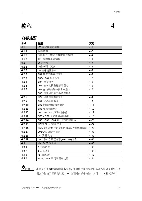
编程 4内容提要章节标题页码4.1NC编程的基本原理4-24.1.1程序结构4-24.1.2位移指令的绝对值和增量值编程4-44.1.3直径编程和半径编程4-44.2G指令码4-54.2.1G指令码一览表4-54.2.2G0快速线性移动4-64.2.3G01带进给率直线插补4-64.2.4G02,G03圆弧插补4-74.2.5G04 暂停指令4-84.2.6G08 轴向机械坐标清零指令4-84.2.7G28自动回归第一参考点指令4-8G30 自动回归第二参考点指令4.2.8G29 自动由参考点复归4-94.2.9G31 跳跃机能指令4-94.2.10G32恒螺距螺纹切削指令4-104.2.11G33攻丝切削循环4-124.2.12G40 G41 G42 刀具半径补偿4-134.2.13G70 ~ G76 复式切削固定循环4-154.2.14G90,G92,G94 单一切削固定循环4-254.2.15G20/G21 公/英制变换4-294.2.16G50,G96G97主轴最高转速设定及恒线速控制4-294.2.17G98/G99进给率设定4-304.2.18G10资料设定4-304.2.19G65 客户自设程序群(MACRO)指令4-314.3M,S,T指令码4-334.3.1S主轴功能4-334.3.2T刀具功能4-334.3.3M 辅助功能4-334.3.4M 98,M99调用子程序功能4-34注释!:本章介绍了NC编程的基本原理,并对程序和程序段的基本结构以及系统的控制指令做出了必要的说明。
NC编程时的操作方法,参见2.4.5程式编辑。
中达电通CNC-H4-T车床系统操作和编程 4-14.1 NC 编程的基本原理数控车床自动加工零件时需要执行NC程序,NC程序也称为工件程式或者零件程序。
编制的NC程序需要使用各种必要的控制指令,从而满足机床对零件的加工要求。
4.1.1程序结构表4-1 NC程序结构% %和程式号码O****在使用DNC 软件和PC传输时需要,通过系统面板录入程序,正常编程时不需要。
HLK-M30使用手册V1.01

HLK-M30 使用手册
WIFI 无线网 串口网络/无线模块Βιβλιοθήκη 深圳市海凌科电子有限公司
目录
1 产品概述........................................................................................................................................................ 4 1.1 概述..................................................................................................................................................... 4 1.1.1 模块特点:...................................................................................................................................... 4 1.1.2 模块基本参数:..............................................................................................................................5 1.1.3 主要应用领域.................................................................................................................................. 6 1.2 硬件介绍............................................................................................................................................. 6 1.2.1 管脚定义.......................................................................................................................................... 7 1.2.2 电气特性.......................................................................................................................................... 9 1.2.3 机械尺寸.......................................................................................................................................... 9 1.2.4 天线................................................................................................................................................ 10 1.2.4.1 外置天线的参数要求.................................................................................................................10 1.2.4.2 推荐板载 PCB 天线................................................................................................................... 10 1.2.5 通用开发测试套件........................................................................................................................ 11 1.2.6 USB 开发测试套件........................................................................................................................ 13 1.3 典型应用........................................................................................................................................... 15 1.3.1 HLK-M30 模块应用的典型电路...................................................................................................15 1.3.2 有 MCU 控制下的最简电路.........................................................................................................16
M340与ATV31的CANopen通信及参数设置案例
Unity M340与ATV31CANopen通信向导<一> ——CANopen通信控制启停、CANopen通信给定速度本向导分为两部分:1.《快速操作指南》---Know How, 满足了客户“快速解决调试问题”的需求。
●发送快---大小在2M左右,能方便快速地通过电子邮件发给客户使用●调试快---提供了反复调试过的完整准确的PLC通信程序,客户可直接下载●接线快---含有实物照片的通信接线图使客户非常容易理解和模仿,并且快速完成接线●设置快---图形化的变频器参数设置指导使客户可直接上手设置参数,不用查找手册2.《完全通信指导》---Know Why, 满足了客户“系统学习通信知识”的需求。
●知识全---不仅给出了详细的调试步骤和详细解释,还使客户在完成通信的同时系统学习相关的产品和通信知识●考虑全---对客户调试可能遇到的各种突发情况给出了相关提示和解决方法●理解易---提供了程序指令和结构的详细注释,使客户能容易的理解和学习提供的标准程序并能在原有程序上进行扩展第二部分完全通信指导重要信息注意:在尝试安装、操作或调试设备之前,请仔细阅读下述说明并通过查看来熟悉设备。
下述特别信息可能会在文本其他地方或设备上出现,提示用户潜在的危险和注意事项,或提供阐明或简化某一过程的信息。
遵守使用说明,可能导致调试失败、人身伤害甚至设备损坏。
此符号的注意事项,以避免不必要的调试错误。
目录1. 实验简介 (4)2. 硬软件环境 (4)3. ATV31变频器设置 (5)3.1 操作说明 (5)3.2 参数设置 (6)3.2.1 控制方式 (7)3.2.2 通信参数 (8)4. 硬件连接 (10)5. PLC编程 (11)5.1 硬件组态 (11)5.1.1 组态CPU (11)5.1.2 组态CANopen主站 (12)5.1.3 配置CANopen网络和从站 (13)5.2 ATV31 内部变量说明 (15)5.2.1 ATV31 内部字 (15)5.2.2 ATV31 DRIVERCOM流程 (16)5.3 编程 (17)6. 实验调试 (20)6.1 计算机与PLC的连接 (20)6.2 软件调试 (22)6.3 ATV31常见通信故障 (23)7. 带多台变频器 (24)7.1 硬件扩展 (24)7.2 软件扩展 (25)7.1.1 同一变频器通信多个变量 (25)7.1.2 连接多个变频器 (25)8. 附件 (26)8.1 Unity M340程序 (26)8.2 ATV31的CANopen用户手册 (26)8.3 ATV31编程手册 (26)8.4 Unity M340 CANopen现场总线用户手册 (26)1. 实验简介在施耐德电器的控制系统中,PLC通过CANopen监控变频器的运行是工业中较常见的应用,本文以施耐德M340 PLC与ATV31变频器为例,简要介绍PLC与变频器之间CANopen通信的过程,包括硬件接线、变频器参数设置、硬软件组态、上电调试等,实现在PLC上远程控制ATV31变频器的故障初始化,启动/停止,正转/反转,频率给定等。
FANUC OI立加编程说明

数控立铣FANUC 0I-MB编程指导詹有斌FANUC OI-MB 编程说明一基本代码G代码组别功能编程示例G04 00 暂停,停刀,准确停止. G04X5 暂停5秒--------------------------------------------------------------------------G05.1 00 AI先行控制。
---------------------------------------------------------------------------G07.1[G107] 00 圆柱插补。
---------------------------------------------------------------------------G08 00 先行控制。
--------------------------------------------------------------------------G09 00 准确停止。
---------------------------------------------------------------------------G10 00 可编程数据输入。
G10 L12 P01 R5:编程输入半径补偿1为5 G11 00 可编程数据输入取消。
--------------------------------------------------------------------------G15 01 极坐标取消。
--------------------------------------------------------------------------G16 01 极坐标指令。
G16 X0 Y0 :X为半径Y为角度--------------------------------------------------------------------------G17,G18,G19 ,02 X/Y X/Z Y/Z 对应平面。
奥里安特电机产品操作手册说明书

HM-9264-2AC Standard Motors Conduit Box TypeInduction MotorThank you for purchasing an Oriental Motor product.This Operating Manual describes product handling procedures and safety precautions.• Please read it thoroughly to ensure safe operation. • Always keep the manual where it is readily available.Before useOnly qualified personnel should work with the product.Use the product correctly after thoroughly reading the section “Safety precautions”.Should you require the inspection or repair of internal parts, contact the Oriental Motor office where you purchased the product. The product described in this manual has been designed andmanufactured for use as an internal component for general industrial equipment, and must not be used for any other purpose. Oriental Motor Co., Ltd. is not responsible for any damage caused through failure to observe this warning.Standard and CE MarkingMotors are recognized by UL. Recognized name are motor model name. Voluntary display of the CE mark conforming to the Low Voltage Directives. StandardsUL 1004, UL 2111, CSA C22.2 No.100, CSA C22.2 No.77 Standards File No. UL File No.E64197 Applications for standardEN 60034-1, EN 60034-5, EN 60664-1A Running Heating Test and a Locked-Rotor Test has beenconducted with a aluminum radiation plate of size indicated below. For the motor with a gearhead, tests has been conducted with a gearhead instead of the radiation plate.First number in motor nameSize [mm (in.)] Thickness [mm (in.)]Material4 135 × 135 (5.31 × 5.31) 5 (40 W) 165 × 165 (6.50 × 6.50) 5 (60 W, 90 W)200 × 200 (7.87 × 7.87)5 (0.20)AluminiumInstallation conditionsOvervoltage category II, Pollution degree 3 (except for the motor mounting surfase and conduit opening), Class I equipment (For EN/IEC standards)When the machinery to which the motor is mounted requiresovervoltage category III specifications, connect to power supply via an isolation transformer.Hazardous substancesRoHS (Directive 2002/95/EC 27Jan.2003) compliant∗ 5IK60GU-FCH , 5IK60GU-ECH , 5IK60GU-SH , 5IK90GU-FCH , 5IK90GU-ECH and 5IK90GU-SH do not comply with the hazardous substances.The precautions described below are intended to prevent danger or injury to the user and other personnel through safe, correct use of the product. Use the product only after carefully reading and fully understanding these instructions.WarningHandling the product without observing theinstructions that accompany a “Warning” symbol may result in serious injury or death.CautionHandling the product without observing theinstructions that accompany a “Caution” symbol may result in injury or property damage.NoteThe items under this heading contain importanthandling instructions that the user should observe to ensure safe use of the product.Warning• Do not use the product in explosive or corrosive environments, in the presence of flammable gases, locations subjected to splashing water, or near combustibles. Doing so may result in fire, electric shock or injury.• Assign qualified personnel the task of installing, wiring,operating/controlling, inspecting and troubleshooting the product. Failure to do so may result in fire, electric shock or injury. • Do not transport, install the product, perform connections or inspections when the power is on. Always turn the power offbefore carrying out these operations. Failure to do so may result in electric shock.• Turn off the power in the event the overheat protection device (thermal protector) is triggered. Failure to do so may result in injury or damage to equipment, since the motor will start abruptly when the overheat protection device (thermal protector) is automatically reset.• To prevent the risk of electric shock, use the motor for class I equipment only.Motore zur Verwendung in Geräten der Schutzklasse I.• Install the motor in an enclosure in order to prevent electric shock or injury.• Install the motor so as to avoid contact with hands, or ground it to prevent the risk of electric shock.Die Gehäuse der Motore sind mit einer Schraube undZahnscheibe sicher mit dem geerdeten Gehäuse des Gerätes zu verbinden.• Keep the input power voltage within the specification to avoid fire and electric shock.• Connect the cables securely according to the wiring diagram in order to prevent fire and electric shock.• Do not forcibly bend, pull or pinch the lead wires. Doing so may result in fire and electric shock.• Turn off the power in the event of a power failure, or the motor will suddenly start when the power is restored and may cause injury or damage to equipment.• Do not touch the connection terminal of the capacitor immediately after the power is turned off (for a period of 30 seconds). Theresidual voltage may cause electric shock.• Do not disassemble or modify the motor. This may cause electric shock or injury.Caution• Do not use the motor beyond its specifications, or electric shock, injury or damage to equipment may result.• Do not touch the motor during operation or immediately after stopping. The surface is hot and may cause a burn.• Do not hold the motor output shaft or motor lead wires. This may cause injury.• Keep the area around the motor free of combustible materials in order to prevent fire or a burn.• To prevent the risk of damage to equipment, leave nothing around the motor that would obstruct ventilation.• To prevent bodily injury, do not touch the rotating parts (output shaft, cooling fan) of the motor during operation.• When an abnormality is noted, turn off the power immediately, or fire, electric shock or injury may occur.• The motor’s surface temperature may exceed70 °C, even under normal operating conditions. Ifa motor is accessible during operation, post thewarning label shown in the figure in aconspicuous position to prevent the risk of skinburn(s).Warning label• To dispose of the motor, disassemble it into parts and components as much as possible and dispose of individual parts/components as industrial waste.Checking the productVerify that the items listed below are included. Report any missing or damaged items to the branch or sales office from which you purchased the product.• Motor...............................................1 unit• OPERATING MANUAL................1 copyChecking the model nameCheck the model number against the number indicated on the product.Model Model Model4IK25GN-FCH 4IK25GN-ECH 4IK25GN-SH4IK25AA-FCH 4IK25AA-ECH 4IK25AA-SH5IK40GN-FCH 5IK40GN-ECH 5IK40GN-SH5IK40AA-FCH 5IK40AA-ECH 5IK40AA-SH5IK60GE-FCH 5IK60GE-ECH 5IK60GE-SH5IK60A-FCH 5IK60A-ECH 5IK60A-SH5IK60GU-FCH 5IK60GU-ECH 5IK60GU-SH5IK90GE-FCH 5IK90GE-ECH 5IK90GE-SH5IK90A-FCH 5IK90A-ECH 5IK90A-SH5IK90GU-FCH 5IK90GU-ECH 5IK90GU-SH Location for installationThe motor is designed and manufactured for installation in equipment.Install it in a well-ventilated location that provides easy access for inspection. The location must also satisfy the following conditions: • Inside an enclosure that is installed indoors (provide vent holes) • Operating ambient temperature−10 to +40 °C (+14 to +104 °F) (non-freezing)−10 to +50 °C (+14 to +122 °F) for three-phase 200 V• Operating ambient humidity 85%, maximum (non-condensing) • Area that is free from an explosive atmosphere or toxic gas (such as sulfuric gas) or liquid• Area not exposed to direct sun• Area free of excessive amount dust, iron particles or the like• Area not subject to splashing water (storms, water droplets), oil (oil droplets) or other liquids• Area free of excessive salt• Area not subject to continuous vibration or excessive shocks• Area free of excessive electromagnetic noise (from welders,power machinery, etc.)• Area free of radioactive materials, magnetic fields or vacuum• 1000 m (3300 ft.) or less above sea levelHow to install the motor• Round shaft typeDrill holes on the mounting plate and fix the motor on the plateusing screws, nuts, and washers (not supplied). Be careful there is nogap between the motor installation surface and the bracket.First number inmotor modelScrew size Tightening torque [N·m (lb-in)]4 M5 2.5(22)5 M6 3.0(26)Do not insert the motor into the mounting hole at anangle or force it in, as this may scratch the flange pilotsection and damage the motor.• Pinion shaft typeDrill holes on the mounting plate and fix the motor and gearhead on the plate using screws supplied with the gearhead. Be careful there is no gap between the motor flange and the gearhead.For details of installation, see the operating manual provided with the gearhead, which is sold separately.Use the gearhead with pinion shaft which is identicalwith one of motor.• Motor with cooling fanWhen installing a motor with cooling fan onto a device, leave10 mm (0.39 in.) or more behind the fan cover or open a ventilation hole so that the cooling inlet on the back of the motor cover is not blocked.Insulate all the wire connections, such as the connection between the motor and the capacitor connection.When the single-phase motor is run in only one direction, unused lead wires should be insulated.Ground the motor using a Protective Earth lead wire (green/yellow). The direction of motor rotation is as viewed from the side of the motor’s output shaft. The motor rotates in a clockwise (CW) and counterclockwise (CCW) direction.• Insulation class of this motor is B. Make sure that themotor case temperature does not exceed 90 °C(194 °F) during operation of the motor. Operationexceeding case temperature 90 °C (194 °F) maysignificantly deteriorate the coils and ball bearings ofthe motor and shorten the motor’s life span. Motorcase temperature can be measured by fixing athermometer on the motor surface. It can also bemeasured using thermo tape or a thermocouple.• To change rotation direction of the single-phasemotor, wait until the motor completely stops.Otherwise its direction may not change or may takemuch time to change.Rotating direction of the gearhead output shaftThe rotating direction of the gearhead output shaft may be opposite that of the motor shaft, depending on the gear ratio. For the rotating direction of the output shaft of a specific gearhead used, refer to the operating manual for the gearhead. Connection method to a terminal box• Open the terminal box and connect wires.• Use applicable cable ground and conduit for conduit opening. • After connecting, close the terminal box with the terminal cover. • Terminal cover screws tightening torqueSingle-phase 25 W, 40 W/Three-phase: 0.3 N·m (2.6 lb-in) Single-phase 60 W, 90 W: 1 N·m (8.8 lb-in)• Single-phase 25 W, 40 W/Three-phase••Connect the motor according to the figure.The connection method will vary, depending on the directionClockwiseLNCounterclockwiseLN∗ NC: Not connect. Three-phase motorsConnect the motor according to the figure.When connected according to the connection diagram, the motor will operate in the clockwise direction (CW) as viewed from the motor’s output shaft. To change the direction of rotation, change any two connections between U, V and W.ClockwiseL2 (S)L1 (R)L3 (T)Motors have a continuous rating.This motor is equipped with the feature listed below to prevent the motor from burning out as a result of abnormal heating which maybe caused by misapplication.• Thermal protection“TP” is stamped on the motor nameplate. The motor has an “auto reset” type thermal protector built into its motor coil. When themotor reaches a predetermined temperature, the internal thermal protector is activated and the motor is stopped.Always turn the power off before performing inspections.Thermal protector activation rangePower is turned off at 130±5 °C (266±9 °F)Power is turned back on at 82±15 °C (180±27 °F)When the motor cannot be operated correctly, refer to the contents provided in this section and take appropriate action. If the problem persists, contact your nearest office.Phenomena CheckitemsMotor does not rotate or rotates slowly. • Check the power supply voltage.• Connect the power supply and the motor correctly.• If terminal blocks or crimp terminals are used, check them for poor connection. • Keep the load at or below the allowable value.Motor sometimes rotates and stops. • Connect the power supply and the motor correctly.• If terminal blocks or crimp terminals are used, check them for poor connection.The motor rotates in the direction opposite to the specified direction. • Connect correctly by referring to “Wiring diagram.”• The rotating direction of the motor output shaft may be different from that of the gearhead output shaft depending on the gear ratio of the gearhead. See the operating manual for the gearhead.• The rotating direction is indicated as viewed from the motor output shaft. Check the reference direction.Motor temperature abnormally high [Motor case temperature exceeds 90 °C (194 °F)] • Check the power supply voltage. • Review the ventilation condition.Noisy operation • Assemble the motor and gearheadcorrectly by referring to the operatingmanual for the gearhead.• Assemble a gearhead of the same piniontype as the motor.• Unauthorized reproduction or copying of all or part of thismanual is prohibited.• Oriental Motor shall not be liable whatsoever for any problems relating to industrial property rights arising from use of anyinformation, circuit, equipment or device provided orreferenced in this manual.• Characteristics, specifications and dimensions are subject tochange without notice.• While we make every effort to offer accurate information in the manual, we welcome your input. Should you find uncleardescriptions, errors or omissions, please contact the nearestoffice.• is a registered trademark or trademark ofOriental Motor Co., Ltd., in Japan and other countries.© Copyright ORIENTAL MOTOR CO., LTD. 2008Printed on Recycled Paper • Please contact your nearest Oriental Motor office for further information.Headquarters Tokyo, JapanTel:(03)3835-0684 Fax:(03)3835-1890Tel:01 47 86 97 50 Fax:01 47 82 45 16Tel:(02)8228-0707 Fax:(02)8228-0708 Technical Support Tel:(800)468-39828:30 A.M. to 5:00 P.M., P.S.T. (M-F)7:30 A.M. to 5:00 P.M., C.S.T. (M-F)E-mail:*****************************Headquarters and Düsseldorf Office Tel:0211-52067-00 Fax:0211-52067-099 Munich Office Tel:089-3181225-00 Fax:089-3181225-25 Hamburg Office Tel:040-76910443 Fax:040-76910445Tel:01256-347090 Fax:01256-347099Tel:02-93906346 Fax:02-93906348Tel:(6745)7344 Fax:(6745)9405KOREATel:(032)822-2042~3 Fax:(032)819-8745Tel:(03)22875778 Fax:(03)22875528Tel:66-2-254-6113 Fax:66-2-254-6114。
全站仪(日本索佳30系)操作说明(中文)

电子全站仪(30系列)操作手册适用型号:SET230R/R3 SET330R/R3 SET530R/R3 SET630R一、注意事项(2)1.第一次使用仪器前,应松开底座开关钮上的紧固螺母;2.禁止带三脚架一起搬动仪器;3.取电池前一定要关断电源;4.激光束不能对着人,有害,更不能从目镜去看;5.仪器每天用完入箱前,应取出电池。
`二、基本操作(5)1.基本键操作(5.1)·开关电源按{ON}:电源开;按住{ON}再按{灯}:电源关。
·开关屏幕按{灯},屏幕背景灯亮灭;按住{灯}直到滴滴响声,开关激光束。
·软键操作(软键指在屏幕内底部的键)按{F1}-{F4},选择需要的软键;{FUNC}键用于在测量方式[MEAS]状态下的屏幕翻页(当多于4个软键时);·输入字母和数字{F1}-{F4}:输入分布在软键上的数字和字母;{FUNC}:翻页找你需要的字母、数字;(按住一会儿)回上页;连续按,往前翻。
{BS}:删除左侧字母数字;{ESC}:取消输入数据;{SFT}:选择的接收靶类型显示;{←}:(回车)接受输入的数据。
·选择键{▲}/{▼}:光标上下移动;{<}{>}:左右移动光标/其它选择;{←}: 确认选择;·模式转换[CNFG]:(软键)从主屏模式到设置(Configuration)模式;[MEAS]:从主屏模式到测量(Measure)模式;[MEM]:从主屏模式到内存存储(Memory)模式;{ESC}:从各状态返回到主屏状态。
·其它操作{ESC}:返回上一屏。
2.屏幕功能距离:S:斜距;H:水平距;V:参考高度;竖向角度:ZA:天顶角(Z=0);VA:竖向角(H=0/H=±90);水平角度:按[R/L]转换状态:HAR:水平右转;HAL:水平左传;按[◢SHV],转换“S,ZA,H”,到“S,H,V”。
3.开机程序(9)开机后,仪器自检。
迅达3300AP操作手册之欧阳歌谷创作

迅达3300AP无机房欧阳歌谷(2021.02.01)3300AP(rel.4版本),有四个按钮,分别是“ESC ↓↑ OK”,四个键。
查故障:1、在标准显示状态下,按OK一次,显示"10"2、按↑键4次,显示"50"3、按OK键,显示"50 0"4、按↑键,显示"50 1"5、按0K键,就能查看最近的故障代码;按↓键,直到显示"E0****",再按↓显示"E1****",依次类推。
E0表示最新的故障。
6、清除故障方法:在显示"e*****"时,一直按住OK键约3秒,显示“",说明清除故障成功。
限速器试验(刹车试验),注意:以下步骤前,先将107改为1(关闭称重),机房检修盒插上。
1、1、在标准显示状态下,按OK一次,显示102、按↑键一次,显示"20 0"3、按↑键一次,显示"20 1"4、按OK键5、显示”20 --",同时电梯跑到最顶层,开门后,6、按↑键直到显示"20 75",按OK键,同时显示"75 1"7、门开始关闭,之后显示"75 2"8、打机房检修,并按”下行键“,待电梯蜂鸣器长响后,按DBV键,刹车。
如果成功会显示"75 1"9、按ok键确认,显示"20 1",按↑键,显示"20 0",按OK键,显示”20“,再按"esc"退回返回主菜单。
10、刹车完后,机房检修拉起轿厢,(如果实在拉不起来,就搬走一部分砝码)11、最后,限速器开关复位操作:在主菜单上按"ok"键一次,显示"10",按OK键一次,显示"101",在按↑键直到显示125,按OK键一次,显示"125 0",按↑键一次,显示"125 1",按OK键一次,限速器开关就复位。
常用设置

设置84 刀具过载操作 这个设置用来决定CURNT COMDS显示中刀具载荷 监控器页面上定义的刀具过载状况(用PAGE DOWN到达该处)。刀具过载状况能够导致控制器 的四种状况,由设置84决定。当发生过载的时候, ALARM将产生一个警告;用Feed Hold停止进给控制; 发出警告蜂鸣声;或者是AUTOFEED将自动减少进 给速率。
设置1 自动断电计时器 机床将在空转设置中规定的分钟数后自动关闭。 设置2 在M30断电 机床将在M30结束程序时自动断电。此外,如果控 制器探测到过电压或者是过热的情况超过4分钟,控 制器本身将自动关闭。 设置8 程序存储器锁定 当这个设置关闭时,可对存储器中的程序进行编辑。 当设置打开时,存储器编辑功能被锁定,程序不能 被删除。
CYCLE START按钮时,一次可以循环您程序中的一
行。如果您开启设置104,进给手轮每一次逆时针旋 转一格,将浏览一行程序。将手轮顺时针旋转将会引
起进给暂停。当程序运行的时候可以改变这个设置。
该设置在设置103打开的情况下不能使用。 (适用于
车床控制版本4.11及以上,铣床控制版本9.06及以上)
设置51 门控制开关覆盖 当这个设置为关,在门开启的情况下将不运行程序。 与FEED HOLD相同,开启门将会引起运行的程序停 止。当它设置为开的时候,参数57 DOOR STOP SP 和SAFETY CIRC被设置为零,门状态被忽略。当控 制器关闭,然后再一次返回的时候,有一些设置会自 动地返回到它的默认状态,当您加电后会关闭, 如果 需要可以将它打开。
铣床控制版本10.22及以上)
设置103 循环开始/的设置。该
设置为开,CYCLE START按钮的功能与Feed Hold键相同。当一直按下CYCLE START的时候, 机床将整个运行程序;当松开它的时候,机床将 在进给控制停止。这将允许您对新程序做更好的