EC系列继电器使用说明书
euchner esm-ba3.. 紧急停机安全继电器 用户手册说明书
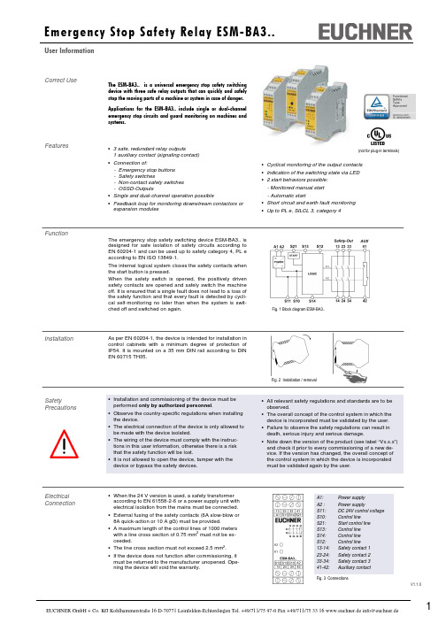
V1.1.0• Cyclical monitoring of the output contacts • Indication of the switching state via LED • 2 start behaviors possible: - Monitored manual start - Automatic start• Short circuit and earth fault monitoring • Up to PL e, SILCL 3, category 4Correct UseThe ESM-BA3.. is a universal emergency stop safety switching device with three safe relay outputs that can quickly and safely stop the moving parts of a machine or system in case of danger. Applications for the ESM-BA3..include singleor dual-channel emergency stop circuits and guard monitoring on machines and systems.Features• 3 safe, redundant relay outputs1 auxiliary contact (signaling contact) • Connection of:- Emergency stop buttons - Safety switches- Non-contact safety switches - OSSD-Outputs• Single and dual-channel operation possible• Feedback loop for monitoring downstream contactors or expansion modulesFunctionThe emergency stop safety switching device ESM-BA3.. is designed for safe isolation of safety circuits according to EN 60204-1 and can be used up to safety category 4, PL eaccording to EN ISO 13849-1.The internal logical system closes the safety contacts when the start button is pressed.When the safety switch is opened, the positively driven safety contacts are opened and safely switch the machine off. It is ensured that a single fault does not lead to a loss of the safety function and that every fault is detected by cycli-cal self-monitoring no later than when the system is swit-ched off and switched on again.Electrical Connection• When the 24 V version is used, a safety transformeraccording to EN 61558-2-6 or a power supply unit with electrical isolation from the mains must be connected. • External fusing of the safety contacts (6A slow-blow or 8A quick-action or 10 A gG) must be provided.•A maximum length of the control lines of 1000 meters with a line cross section of 0.75 mm 2 must not be ex-ceeded.• The line cross section must not exceed 2.5 mm 2. •If the device does not function after commissioning, it must be returned to the manufacturer unopened. Ope-ning the device will void the warranty.InstallationAs per EN 60204-1, the device is intended for installation in control cabinets with a minimum degree of protection of IP54. It is mounted on a 35 mm DIN rail according to DIN EN 60715 TH35.SafetyPrecautionsFig. 1 Block diagram ESM-BA3..Fig. 2 Installation / removalFig. 3 ConnectionsA1: Power supply A2 : Power supplyS11: DC 24V control voltage S10: Control line S21: Start control line S13: Control line S14: Control line S12: Control line13-14: Safety contact 1 23-24: Safety contact 2 33-34: Safety contact 3 41-42: Auxiliary contact(not for plug-in terminals)• All relevant safety regulations and standards are to beobserved.• The overall concept of the control system in which the device is incorporated must be validated by the user. • Failure to observe the safety regulations can result in death, serious injury and serious damage.• Note down the version of the product (see label “Vx.x.x”) and check it prior to every commissioning of a new de-vice. If the version has changed, the overall concept of the control system in which the device is incorporated must be validated again by the user.• Installation and commissioning of the device must be performed only by authorized personnel .• Observe the country-specific regulations when installing the device.• The electrical connection of the device is only allowed to be made with the device isolated.•The wiring of the device must comply with the instruc-tions in this user information, otherwise there is a risk that the safety function will be lost.•It is not allowed to open the device, tamper with the device or bypass the safety devices.V1.1.0Note: The items listed under “Electrical connection” must be observed during commissioning. Commissioning Procedure1. Wiring emergency stop circuit:Wire the emergency stop circuit according to the required Performance Level determined (see Fig. 1 to Fig. 5). 2. Wiring start circuit:Wire the start circuit according to Fig. 6 or Fig. 7 to set the starting behavior. Warning:If “Automatic start” is set, bear in mind that the safety con-tacts will switch immediately after the power supply is connected. If “Monitored manual start” is set, the start button must be opened after wiring. 3. Wiring feedback loop:If your application provides for external contactors or ex-pansion modules, connect them to the device according to Fig.8 or Fig. 9.4. Wiring power supply:Connect the power supply to terminals A1 and A2 (Fig. 10). Warning: Wiring only in de-energized state.5. Starting the device:Switch the operating voltage on. Warning:If the “Automatic start” starting behavior is set, the safety contacts will close immediately.If the “Monitored manual start” starting behavior is set, close the start button to close the safety contacts. LEDs K1 and K2 are lit.6. Triggering safety function:Open the emergency stop circuit by actuating the connec-ted safety switch. The safety contacts open immediately. 7. Reactivation:Close the emergency stop circuit. If “Automatic start” is selected, the safety contacts will close immediately.If the “Monitored manual start” starting behavior is set, close the start button to close the safety contacts.Fig. 6:Monitored manual start. It is monitored that the start button was opened before the emergency stop button closes. (Prerequisite: operating voltage must not be interrupted.)Fig. 7:Automatic start.Max perm. delay during closing of the safety switches on S12 and S13:S12 before S13: 300 ms S13 before S12: anyWarning:Safety contacts switch immediately when thepower supply is connected.Depending on the application or the result of the risk assessment according to EN ISO 13849-1, the device must be wired as shown in Fig. 1 to Fig. 11.ApplicationsFig. 3:Single-channel emergency stop circuit with earth fault monitor-ing.(category 1, up to PL c)Fig. 2:Two-channel emergency stop circuit with earth fault monitoring. (category 3, up to PL d)Fig. 1:Two-channel emergency stopcircuit with short circuit and earth fault monitoring.(category 4, up to PL e)Fig. 4:Two-channel sliding guardmonitoring with short circuit and earth fault monitoring. (category 4, up to PL e)Emergency Stop CircuitStarting BehaviorFig. 5:Two-channel emergency stop with pnp-outputs/OSSD-outputs with short circuit monitoring. (category 4, up to PL e)Fig. 8:Feedback loop for monitored manual start:The feedback loop monitors contactors or the expansion modules .Feedback LoopFig. 9:Feedback loop for automatic start: The feedback loop monitors contac-tors or the expansion modules .Power supply andSafety contactsFig. 10:Power supply A1 and A2.(Power supply according to techn. data )Fig. 11:Connecting load to safety contacts.(Figure shows example.Voltage …+V“ according to techn. data)Notice:In order to activate earth fault monitoring, S10 must be con-nected to PE (protective earth) on the AC115/230V devices. With AC/DC 24V, connect PE only to the power supply unit according to EN60204-1.V1.1.0MaintenanceThe device must be checked once per month for proper function and for signs of tampering and bypassing of the safety function.Techn. DataOperating voltage ESM-BA301 ESM-BA302 ESM-BA303AC/DC 24V AC 115V AC 230V Rated supply frequency 50-60 Hz Permissible deviation + / - 10% Power consumption DC 24V AC 230Vapprox. 2.3 W approx. 6.9 VA Control voltage at S11 DC 24 VControl current S11...S14 approx. 60 mA Safety contacts 3 NO contacts Auxiliary contacts 1 NC contact Max. switching voltageAC 250 VSafety contact breaking capacity (13-14, 23-24, 33-34) AC: 250 V, 2000 VA, 8 A for ohmic load, 250 V, 3 A for AC-15DC: 50 V, 400 W, 8 A for ohmic load; 24 V, 3 A for DC-13Max. total current through all 3 contacts15 A (13-14, 23-24, 33-34) *)Auxiliary contact breaking capacity (41-42) AC: 250 V, 500 VA, 2 A for AC-12 DC: 50 V, 100 W, 2 A for DC-12 Minimum contact load 24 V, 5 mAContact fuses 6 A slow-blow or 8 A quick-action or 10 A gG Line cross section 0.14 - 2.5 mm 2Max. length of control line 1000 m with 0.75 mm 2 Contact material AgNiContact service life mech. approx. 1 x 10⁷Test voltage2.5 kV (control voltage/contacts) Rated impulse withstand voltage, leakage path/air gap 4 kV (DIN VDE 0110-1) Rated insulation voltage 250 V Degree of protection IP20Temperature range -15°C to +40°C *) Degree of contamination 2 (DIN VDE 0110-1) Overvoltage category 3 (DIN VDE 0110-1) Weight approx. 230 gMounting DIN rail according to EN 60715TH35SafetyCharacteristics According to EN ISO 13849-1Note:Additional data can be requested from the manufacturer for applications that deviate from these conditions.The device is certified according to EN ISO 13849-1 up to a Performance Level of PL e.Device cannot be switched on again after an emergency stop:• Check whether the emergency stop circuit was closed again.• Was the start button opened before closing of the emer-gency stop circuit (with manual start)? • Is the feedback loop closed?If the fault still exists, perform the steps listed under “Commissioning Procedure”.If these steps do not remedy the fault either, return the device to the manufacturer for examination.Opening the device is impermissible and will void the warranty.Device does not switch on:• Check the wiring by comparing it to the wiring diagrams. • Check the safety switch used for correct function and adjustment.• Check whether the emergency stop circuit is closed. • Check whether the start button (with manual start) is closed.• Check the operating voltage at A1 and A2. •Is the feedback loop closed?What to Do in Case of a Fault?The device is otherwise maintenance free, provided that it was installed properly.*) If several ESM-BA3.. devices are closely spaced under load, the max. total current at the ambient temperature of T=20°C: 9A; at T=30°C: 3A; at T=40°C =1A. If these currents are exceeded, a spacing of 5 mm between the devices must be observed.Safety characteristics according to EN ISO 13849-1 for all variants of ESM-BA3 Load (DC-13; 24V) <= 0,1A <= 1A <= 2A T10d [years] 20 20 20 Category: 4 4 4 PLe e e PFHd [1/h]: 1,2E-08 1,2E-08 1,2E-08 nop [cycle / year]<= 500.000<= 350.000<= 100.000V1.1.0Dimension DrawingS u b j e c t t o t e c h n i c a l m o d i f i c a t i o n s , n o r e s p o n s i b i l i t y i s a c c e p t e d f o r t h e a c c u r a c y o f t h i s i n f o r m a t i o n . © E U C H N E R G m b H + C o . K G 090073-05-05/14 (T r a n s l a t i o n o f t h e O r i g i n a l O p e r a t i n g I n s t r u c t i o n s )。
欧瑞 EC200 系列 PLC 用户手册说明书

序言感谢您选用EC200系列PLC产品!本公司以:完美的质量,竭诚的服务,给您最真挚的回报。
EC200系列PLC由欧瑞传动电气股份有限公司自主设计与研发,融合国际主流PLC的成功经验,改进其不足之处、瞄准当今PLC的最新发展方向,采用计算机、通信、电子和自动控制等领域的最新技术,在CPU性能、I/O 信号处理、现场总线通讯、软件开发及生产工艺等方面都具有优良性能。
EC200是对传统PLC功能的极大提升,其组网的灵活性、系统平台的开放性、编程软件的标准性以及智能性可使复杂的控制过程得以完美地实现。
目录第一章概述 (5)1.1产品应用领域 (6)1.1.1模块的命名规则 (7)1.1.2订货号的命名规则 (8)1.2EC200系列PLC产品型号及规格 (9)1.3使用规范 (11)1.3.1工作环境 (11)第二章产品体系结构 (13)2.1 模块的外形尺寸及安装 (14)2.2 可插拔端子的拆卸方式 (19)第三章CPU模块 (20)3.1CPU结构 (21)3.1.1CPU模块整体视图 (21)3.1.2运行状态指示、开关、和顶调电位器 (21)3.1.3CPU本体I/O (22)3.2CPU高级功能 (23)3.3硬件原理 (24)3.4扩展总线接口 (24)3.5电源计算 (25)3.6传感器电源接口 (26)3.7通讯口 (26)3.8技术参数 (26)3.9接线图 (29)第四章数字量扩展模块 (36)4.1DI扩展模块 (36)4.1.1DI8×DC24V (36)4.1.2DI16×DC24V (38)4.2DO扩展模块 (41)4.2.1DO8×DC24V (41)4.2.2DO8×继电器 (44)4.2.3DO16×DC24V (47)4.2.4DO16×继电器 (50)4.3DI/DO扩展模块 (53)4.3.1DI 4×DC24V,DO 4×DC24V (53)4.3.2DI 4×DC24V,DO 4×继电器 (57)4.3.3DI 8×DC24V,DO 8×DC24V (60)4.3.4DI 8×DC24V,DO 8×继电器 (64)第五章模拟量扩展模块 (69)5.1AI扩展模块 (69)5.1.1AI4×IVM,多信号输入,自带RS485通讯端口,支持远程连接 (69)5.1.2AI 4×RDM,热电阻输入,自带RS485通讯端口,支持远程连接 (73)5.1.3AI 4×TCM,热电偶输入,自带RS485通讯端口,支持远程连接 (77)5.2AO扩展模块 (80)5.2.1AO 4×IVM,多信号输出,自带RS485通讯端口,支持远程连接 (80)5.3AI/AO扩展模块 (84)5.3.1AI 2×IV,AO 2×IV,模拟量输入输出,自带RS485通讯端口,支持远程连接 (84)敬告用户 (89)第一章概述本章简要介绍了EC200系列小型一体化可编程控制器的基本信息,主要内容为:产品的型号及规格、命名规则说明、使用产品的注意事项等,有助于用户初步了解产品的构成和使用规范。
PLC输出电路(继电器,晶体管,晶闸管输出)区别,PLC输出类型选择和注意事项

P L C输出类型选择及其使用中的注意事项摘要:本文简要比较了PLC的继电器和晶体管两种输出类型的工作原理及特点,提出了在选型和使用中应注意的事项。
关键词:PLC输出类型、继电器、晶体管1.引言PLC的输出类型有继电器和晶体管两种类型,两者的工作参数差别较大,使用前需加以区别,以免误用而导致产品损坏。
本文简要介绍了继电器和晶体管输出的特点及使用中的注意事项。
2.继电器和晶体管输出工作原理继电器是一种电子控制器件,它具有控制系统(又称输入回路)和被控制系统(又称输出回路),通常应用于自动控制电路中,它实际上是用较小的电流去控制较大电流的一种“自动开关”。
电磁式继电器一般由铁芯、线圈、衔铁、触点簧片等组成的(如图1所示)。
只要在线圈两端加上一定的电压,线圈中就会流过一定的电流,从而产生电磁效应,衔铁就会在电磁力吸引的作用下克服返回弹簧的拉力吸向铁芯,从而带动衔铁的动触点与静触点(常开触点)吸合。
当线圈断电后,电磁的吸力也随之消失,衔铁就会在弹簧的反作用力返回原来的位置,使动触点与原来的静触点(常闭触点)吸合。
这样吸合、释放,从而达到了在电路中的导通、切断的目的。
从继电器的工作原理可以看出,它是一种机电元件,通过机械动作来实现触点的通断,是有触点元件。
图1电磁式继电器结构图晶体管是一种电子元件,它是通过基极电流来控制集电极与发射极的导通。
它是无触点元件。
3.继电器与晶体管输出的主要差别由于继电器与晶体管工作原理的不同,导致了两者的工作参数存在了较大的差异,下面以艾默生EC系列PLC相关数据为例进行比较说明(输出口主要规格参见表1)(1)驱动负载不同继电器型可接交流220V或直流24V负载,没有极性要求;晶体管型只能接直流24V负载,有极性要求。
继电器的负载电流比较大可以达到2A,晶体管负载电流为0.2-0.3A。
同时与负载类型有关,具体参见表1。
表1输出端口规格(2)响应时间不同继电器响应时间比较慢(约10ms-20ms),晶体管响应时间比较快,约0.2ms-0.5ms,Y0、Y1甚至可以达到10us。
埃斯顿EC-350P 500P机器人专用焊机说明书
EC-350P/500P 机器人专用焊机使用说明书山东埃斯顿电气有限公司中国●济南2017.03感谢您选用埃斯顿机器人专用焊机。
为了您的安全、健康并正确使用该产品,请您在使用前,详细地阅读使用说明书。
谢谢您的合作!目录1.用途及特点 (1)2.安全注意事项 (2)3.电磁兼容注意事项 (4)4.焊机安装 (6)5.焊接电源 (8)6.送丝机构................................................................. 错误!未定义书签。
7.焊枪 (20)8.水冷机 (22)9.设备保养 (24)10.常见故障及原因 (27)11.技术资料 (32)1.用途及特点EC-350P/500P系列机器人专用焊机具有脉冲、恒压、焊条、氩弧四种焊接方式。
可实现碳钢及不锈钢、铝及其合金、铜及其合金等有色金属的焊接。
本产品采用全数字的控制方式,适应性极强,能与市面上几乎所有的弧焊机器人通过数字/模拟接口完成通讯。
性能特点如下:配套机器人种类丰富,能与FANUC、KUKA、ABB、安川、新时达、埃斯顿、新松、COMAU柯马、IGM等系列机器人完成配套。
数字接口控制种类丰富,能直接调用客户存储的焊接参数。
焊接飞溅极小,焊缝成形美观。
优化的引弧、收弧、去球功能。
全数字化控制系统,实现焊接过程的精确控制、弧长稳定。
强大的数字报错功能,每种故障都有错误代码进行显示。
系统内置焊接专家数据库,自动智能化参数组合。
操作界面友好,一元化调节方式,易于掌握。
软开关逆变技术,整机可靠性高、节能省电。
该焊接电源的制造符合标准GB15579.1-2013《弧焊设备第1部分:焊接电源》。
2.安全注意事项一般安全注意事项●请务必遵守本说明书规定的注意事项,否则可能发生事故。
●输入电源的设计施工、安装场地的选择、高压气体的使用等,请按照相关标准和规定进行。
●无关人员请勿进入焊接作业场所内。
Ultra EOTec 2000 系统概述(PLC 串行通信) 说明书

EOTec 2000 系统概述(PLC/串行通信)Ultra Electronics 公司生产的 EOTec 2000 光纤转换器包括一系列模块,这些模块设计用于连接传统的铜缆网络,将其承载的信号转换成光纤信号,然后再转换回去。
所有的模块都可装配到标准的 35mmDIN 导轨,每个模块有一个集成底板。
这样便不需要去单独购买底板,模块之间也不需要外部配线,只需要简单地将模块装入 DIN 导轨,滑动它们直到相互紧密配合到一起。
对于使用铜缆来互连通讯节点所遇到的传统性问题,EOTec 2000系列是一种非常灵活且易于扩展的解决方案。
它不仅支持多模光纤链路,而且还支持单模光纤链路。
它提供多种选择方案,支持所有的常用光纤接头(ST 、SMA 、SC 等),帮助用户架构可靠、耐用的网络。
通过使用 EOTec 2000 光纤转换器,可以消除诸如接地回路、绝缘、雷击等问题。
光纤通信链路也可以延伸到更长许多的距离,并能容纳铜缆网络所没有的物理拓扑结构。
例如,使用铜缆互联时,不可能采取星形和自愈环拓扑结构。
但使用 EOTec 2000 则可以轻松实现这些配置。
只要用户记住一些简单的指导原则,架构光纤通信节点就非常容易。
用户至少应该知道,每个光纤节点都需要一个电源模块 (PSM)、电气接口模块 (EIM) 以及光接口模块 (OIM)。
电源模块 (PSM)这个模块将接受用户的直流或交流电源输入,并向接插到底板接头的任何模块提供直流电压。
电源模块的部件号总是以 2A 开头,如 2A08 是直流电源。
关键的选用标准:9 安装现场提供交流电还是直流电?9 是否要求提供冗余配置?网站:点到点 菊花链星形电气接口模块 (EIM)这个模块将连接到铜缆通信链路。
它将接收铜缆链路传输的信号,调制这些信号,然后向底板提供信号以便进行转换。
EIM 也接收底板传输的信号,然后再将这些信号传输给所连接的铜缆链路。
用户必须为要转换的铜缆协议选择合适的 EIM。
继电器_EVR150CI_150A_800V-产品规格书说明书

EVR150CI继电器规格书1、技术参数注)①.在微小负载水平下能够通断的下限目标值。
该值有时会根据通断频率、环境条件、所期待的可靠水准发生改变,因此在使用时,推荐在实际负载下进行确认②. 寿命测试通断时间:通0.3s,断2.7s,使用二极管时,触点复位时间可能会延迟,电寿命可能会下降,敬请注意。
2、外形尺寸图技术要求:1、未注公差按公差列表。
2、外观无脏污、划伤等不良,标签需正确。
3、安装底部平面度要求:≤0.5mm。
4、出货包装满足功率继电器出货包装标准要求。
※配套连接器信息(选配)母端品牌:矢崎护套:7283-1020金属端子:7116-4020※配套螺丝(选配)规格:GB9074.13十字槽凹穴六角头螺栓组合件_M4×10_8.8级3、标贴信息4、出货检验项目(at 23℃)● 外观检查 ● 尺寸检查 ● 吸合电压 ● 释放电压 ● 额定动作电流 ● 接触电阻 ● 耐电压 ●绝缘电阻5、 正确使用注意事项:⏹ 工作电压1) 吸合电压、释放电压会随着环境温度和使用条件而发生变化,因此敬请注意。
2) 施加的电压超过最大施加电压时,线圈中的异常升温会缩短绝缘涂层的寿命而发生线圈烧损和层间短路,因此请务必注意。
另外,使用环境温度的范围也请注意不要超过使用范围。
3) 对于这款继电器,如果额定电压(或电流)长时间施加到线圈和接点上,然后关闭并立即打开,则线圈温度和线圈电阻将比平时高。
这意味着操作电压也比平时高,超过了额定值(“热启动”)。
在这种情况下,应采取适当措施,例如降低负载电流和通电时间或限制使用环境温度,防止施加额定操作电压以上的线圈电压等。
4) 线圈长期连续通电时,受线圈自身发热的影响,会促使线圈的绝缘发生劣化。
5) 额定值中的主触点额定值均为电阻负载时的数值。
使用L/R>1ms 的感性负载(L 负载)的情况下,请与感性负载并行采取浪涌吸收措施。
未采取措施的情况下,可能会造成电气寿命下降、发生切断不良。
丹弗斯ECL 210控制器说明书
参数表ECL 舒适210及远程控制单元ECA30/311VD.KT.W1.02 © Danfoss 04/2010DEN-SMT/DK描述ECL210舒适系列ECL210舒适控制器:ECL210舒适控制器是一款属于ECL 家族中的电子气候补偿式温度控制器。
ECL 系列是应用于区域供热、中央空调的制热和制冷系统中的专用控制器。
ECL210最多可对3个回路进行控制,通过使用应用程序卡实现不同应用的选择。
它专为舒适温度,优化能源消耗而设计,通过ECL 应用程序卡(插入-运行)实现安装方便和用户友好的操作方式。
通过气候补偿,分时供热,对供水温度进行调节;通过一次网回水温度、流量和热量限制对供水温度进行优化,这些使节能变得更加容易。
控制器具备例如数据记录和报警等附加功能。
ECL 舒适210操作简单,可使用拨轮(多功能旋钮)或远程控制单元(RCU )。
拨轮和具有图形和文字菜单的显示界面可对用户进行引导。
ECL 舒适210控制器有可控硅输出对电动阀进行控制,继电器输出对循环泵/转换阀进行控制,或作为报警输出。
输入端最多可连接6个Pt1000温度传感器。
此外,2 个可配置输入可以被选择为Pt1000温度传感器,模拟输入(0—10 V)或数字量输入。
控制器可实现墙体或导轨安装。
ECL210B (无显示及操作拨轮)可安装于控制柜内,操作可通过安装于面板上的ECA30/31实现。
ECL210舒适控制器是一款独立控制器,但是可通过ECL 485总线与RCU 或ECL210/310进行通讯。
远程控制单元(RCU ):ECA30/31可对室内温度进行控制,通过4芯双绞线与ECL 控制器进行连接(由ECL485总线供电)。
ECA30/31有一个内置的室内温度传感器。
但可外接一个室内温度传感器,此时,内置的传感器失效。
ECA31还具有一个湿度传感器,在相关的应用程序中可被使用。
同一个ECL485总线中可最多连接2个RCU ;一个RCU 可最多连接10个ECL 控制器(主/从系统)。
海尔 EC6002-JT3U1 60升速热节能横式电热水器 使用说明书

出水管中的阻垢材料有寿命期限,根据当地水质情况,需定期进行更换。对于连 接Wi-Fi的用户,阻垢材料寿命到期时APP界面会出现提示更换信息,可联系售 后人员上门更换带有阻垢功能的出水管。(带有阻垢功能的出水管为耗材,不在保 修范围之内,更换需收费)。
售后服务
感谢您使用海尔产品,我公司将按照《中华人民共和国消费者权益保护法》的有关 规定为您提供优质的服务。 1.您可凭正规商场提供的本机有效购买发票原件享受我公司为您提供的以下服 务: ⑴ 整机包修三年,期间发生性能故障免费维修。内胆漏水,自购买日起八年内置换
明书的步骤操作。阅后妥善保存说明书。自始至终,海尔的“星级服务”将伴随着 您,使用时无论有什么问题,请按说明书上的电话、地址联系,我们时刻恭候为您 服务。
the future is NOW! 再次感谢您选择使用海尔产品,由于产品的改进,您所得到的海尔电热水器可能 与说明书中图示不完全一致,谨此致歉。
“在线客服”进行监督、评价。 如果您的产品有服务需求,欢迎体验海尔智家自助服务专区(预约服务、一键安装、 一键维修):
手 机 搜 索 安 装 “ 海 尔 智 家 ”A P P ,您 可 通 过 “ 智 家 服 务 ” 版 块 选 择 安 装 、 维 修 等 服
务。
如 您 需 要 选 购 更 多 产 品 , 可 在 “ 海 尔 智 家 ”A P P - “商 城 ” 进 行 选 购 。 ( 更 便 捷 、
含有的其 他部件及其均质材料
○
均不含有害物质。
*明细表中含有害物质的所有部
件及其均质材料,均符合欧盟
○
ROHS对有害物质限制使用的
严格要求,请放心使用。
○
温馨提示:
- 1、下载文档前请自行甄别文档内容的完整性,平台不提供额外的编辑、内容补充、找答案等附加服务。
- 2、"仅部分预览"的文档,不可在线预览部分如存在完整性等问题,可反馈申请退款(可完整预览的文档不适用该条件!)。
- 3、如文档侵犯您的权益,请联系客服反馈,我们会尽快为您处理(人工客服工作时间:9:00-18:30)。
EC系列继电器
使用说明书
在使用本产品之前,请务必先仔细阅读本使用说明书请务必妥善保管好本书,以便日后能随时查阅请在充分理解内容的基础上,正确使用。
警告:为避免发生触电,请勿打开机盖,机内没有用户可维修的部件。
此符号提醒用户本产品内部存在危险高电压,小心触电。
与设备内部任何部件的任何形式接触都有触电危险。
此符号表示重要使用和操作说明,用户必须遵守。
本产品必须有可靠的接地保护
重要安全说明
1、使用产品前,必须仔细阅读本说明书中所有安全和使用说明,违反说明书操作可能发生危险或损坏
设备;
2、说明书请妥善保存,供以后查阅;
3、本产品必须使用110V-230V、50Hz/60Hz交流电源,不能使用与本产品额定电压及频率不符的电源;
4、本产品电源输入线应当接在额定电压220V、额定电流大于40A带漏电保护装置的空气开关输出端口,
不宜安装插头。
5、请勿进行过度弯曲、拉扯、扭转和撞击等可能损坏电源线的操作,电源线应布置在不会被踩到或被
上方或旁边物体挤压远离热源的位置;
6、本设备需要接地保护,用户必须确保其安装符合电气技术规程并可靠接地,接地不好可能造成触电;
7、本设备严禁用潮湿的手操作;
8、不要将本设备嵌入书柜或橱柜等受限制的空间,除非有适当的通风条件;
9、不要将本设备放置在电暖炉或暖气片附近或上方,或阳光可直射的地方;
10、请勿将蜡烛、烟灰缸、可燃气体或易爆物质等产热物件放置在设备上方或附近;
11、不要将花瓶、盛有水或液体的容器放置在本设备上;
12、不要将本设备暴露在雨中或靠近浴缸、水盆、水槽、洗衣池或游泳池等潮湿有水的地方;
13、在雷电天气或无人看管或长时间不用等情况下,为更好保护本设备,请断开进线电源,预防设备
在雷电期间或电源线路出现电涌损坏设备;
14、切勿将非插头物件插入本设备的洞孔,否则可能导致电击危险;
15、为防止电击,切物接触设备的内部;
16、设备异常,特别是出现不寻常的声音或气味,请立刻切断电源后联系授权经销商或服务中心;
EC系列-继电器协议
1.通讯参数:
RS485通讯接口波特率:9600 校验方式:无校验数据位:8 停止位:1
正确接收反馈格式:(仅适用设备ID或设备设置通道)
错误接收反馈格式:(仅适用设备ID或设备设置通道)
注解:FE是广播ID,16进制显示, 在单独控制时按照模块数码管显示的ID进行操作;
端口:是指模块的开关通道,最多16路端口,16进制显示;
状态:01是开,00是关,02是取反;
正确接收反馈格式:(仅适用设备ID或设备设置通道)
端口有效选择字节:
用以指明设备的哪些端口进行操作,其0位对应端口1,1位对应端口2 ……7位对应端口8。
位值为1时表示对应端将根据端口状态操作字节的内容进行操作;为0时则表示对应端口保持原有状态。
端口状态操作字节:
用以指明要达到的端口状态,其0位对应端口1,1位对应端口2 ……7位对应端口8。
位值为1时表示开启对应的端口(继电器闭合),为0时则表示关闭对应的端口(继电器释放)。
延时参数字节:用以指明此指令的端口操作的延时时间,其延时时间见下表。
秒单位定时:
分钟单位定时:
举例:
反馈格式:
端口状态字节:
用以指明端口状态,其0位对应端口1,1位对应端口2 ……7位对应端口8。
位值为1时表示开启对应的端口(继电器闭合),为0时则表示关闭对应的端口(继电器释放)。
6.互锁设置:
状态:01为1、2通道互锁;02为3、4通道互锁;04为5、6通道互锁;08为7、8通道互锁; 0F是通道1、2,3、4,5、6,7、8互锁;F0是通道9、10,11、12,13、14,15、16互锁。