德国ScanLab公司hurrySCAN20振镜说明书
激光振镜标刻软件说明书中文版

鑫刻激光振镜标刻软件用户使用手册软件版本:V2.0修订日期:2012年12月由于软件升级所造成的实际操作方式、功能设置等,如有与本手册不符之处,以软件为准。
目录第一章:鑫刻激光振镜标刻软件介绍 (3)1.1 软件简介 (3)1.2 软件安装 (3)1.3 软件功能 (5)1.4 软件设置 (5)1.5软件界面 (7)第二章:快速入门 (11)2.1 启动系统 (11)2.2 输入打标文件 (11)2.2.1打开旧文件 (11)2.2.2 直排文字的输入 (11)a 直排文字b. 置中c. 文字对齐方式d. 步距e. 单字属性f. 字体设置g. 填充h. 矩阵排列2.2.3 弧排文字的输入 (16)2.2.4 序列号的输入 (16)2.2.5 日期的输入 (17)2.2.6 时间的输入 (18)2.2.7 可变文本的输入 (18)2.2.8 组合替换 (19)2.2.9 数据库参数设置 (19)2.3 图形文件 (20)2.3.1 简单图形 (20)2.3.2 交互式图形 (22)a. PLT文件b. DXF文件c. AI文件d. IMG图片文件2.3.3 一维条码 (25)2.3.4 二维条码 (25)2.3.5 刻度盘 (27)2.3.6 旋转打标文件输入 (27)2.4打标参数设置 (28)2.4.1 图层参数 (28)2.4.2 延迟参数 (31)a. 跳转延时b. 开光延时c. 关光延时d. 折点延时2.5 引导红光 (33)2.5.1 定位域设置 (33)2.5.2 红光测试 (34)2.5.3 指定红光位置 (34)2.6 打标 (35)第三章:系统参数设置 (37)3.1 振镜设置 (37)3.2 辅助轴设置 (38)3.3 校正参数设置 (40)第四章:扩展功能 (42)4.1 多工位旋转打标 (42)4.2 数据库设置 (45)第五章:文件编辑示例第一章鑫刻激光振镜标刻软件介绍1.1 软件简介鑫刻软件由市鑫刻光电设计的激光振镜标刻专用软件,功能强大,简易的菜单操作方式,可打印各种中英文字体、矢量图形PLT、DXF文件、点阵图形BMP文件、序列、条形码和二维码、刻度尺。
intelliweld 系列3D 振镜说明书
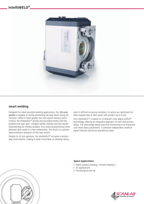
smart weldingintelli WELD ®Typical Applications:• Robot-assisted welding (“remote welding”) • 3D applications• Processing-on-the-flyDesigned for robot-assisted welding applications, this 3D-scan system is capable of swiftly positioning the laser beam along 3D contours. While a robot guides the scan system along a part’s contour, the intelli WELD ® quickly and accurately moves and fine-positions the laser spot. Complex robotic motions and fast robotic repositioning are thereby avoided, thus reducing positioning times between spot welds to a few milliseconds. The result is a substan-tially enhanced utilization of the laser source.Despite its 30 mm aperture, the intelli WELD ® occupies a remark-ably small volume, making it easily mountable on welding robots,even in difficult-to-access locations. Its optics are optimized for fiber-coupled disk or fiber lasers with powers up to 8 kW. The intelli WELD ® is based on SCANLAB’s fully digital i DRIVE ® technology, offering an integrated approach to laser and process safety. The technology allows real-time monitoring of all important scan head status parameters. A software-independent interlock signal indicates abnormal operational states.SCANLAB America, Inc. · 100 Illinois St · St. Charles, IL 60174 · USA Tel. +1 (630) 797-2044 · Fax +1 (630) 797-2001info@ · SCANLAB AG · Siemensstr. 2a · 82178 Puchheim · Germany Tel. +49 (89) 800 746-0 · Fax +49 (89) 800 746-199 info@scanlab.de · www.scanlab.de Specifications (all angles are in optical degrees) Wavelength1030 nm - 1085 nm (1)Maximum laser power(with specified cooling)8000 WCharacteristics of the collimator Focal length 110 mm Limiting numerical aperture typ. 0.125 (2)Fiber adapterQBH , Q 5 /L LK-B, Q D /L LK-D (other types on request)Step response time (with step tuning)(settling to 1/1000 of full scale)1% of full scale 1.2 ms 10% of full scale 3.5 ms 100% of full scale 11 ms Typical speeds (with vector tuning)Processing Speed 4 rad/s Positioning Speed 50 rad/s Dynamic performance Tracking error 0.6 ms Repeatability (RMS)< 2 µrad Long-term drift over 8 h (after warm-up)< 0.6 mradOptical performance Typical scan angle ±0.35 rad Gain error < 5 mradNonlinearity< 3.5 mrad / 44°Power requirements±(15+1.5) V DC, max. 8 A eachInput and output signals SL2-100 oroptical data transfer (XY2-100-O)Weight 21 - 37 kg Operating temperature 25 °C ± 10 °C Typical water requirements3 l/min at 20°C and∆p < 0.1 bar, p < 4 bar (1)mirror coatings for 1030 nm, 1055 - 1085 nm and1070 - 1085 nm are currently available (2)adapters for smaller numerical apertures are availableTypical Optical ConfigurationsPre-Objective scanningPost-Objective scanning Focal length of focusing optics 330 mm 460 mm660 mm Free operating distance 382 mm 488 mm472 mmImage volume size(cuboid-shaped)(185 x 185 x 80) mm 3(220 x 220 x 140) mm 3(370 x 370 x 200) mm 3Image field size (elliptical)(240 x 200) mm 2(385 x 270) mm 2approx. (450 x 450) mm 2Focus range in z direction ±40 mm ±70 mm up to ±100 mm Focus diameter 600 µm(with 200 µm fiber)630 µm(with 150 µm fiber)600 µm(with 100 µm fiber)Fiber diameter 150 µm or 200 µm 100 µm, 150 µm or 200 µm 50 µm or 100 µm Image scale1:31:41:612 / 2014 I n f o r m a t i o n i s s u b j e c t t o c h a n g e w i t h o u t n o t i c e . P r o d u c t p h o t o s a r e n o n -b i n d i n g a n d m a y s h o w c u s t o m i z e d f e a t u r e s .。
蓝光切胶仪BL-20操作说明书

操作说明书Operations Manual BL-20LED Transilluminator蓝光切胶仪目录前言 (1)开箱检查 (1)第一部分安全信息 (2)1.安全操作信息 (2)2.安全提示 (2)第二部分产品说明 (3)1.产品简介 (3)2.产品特性 (3)3.使用环境 (3)4.技术参数 (4)第三部分功能介绍 (5)产品结构图 (5)第四部分操作说明 (6)1.仪器准备 (6)2.仪器操作 (6)第五部分故障排除 (7)第六部分维护与清洁 (8)第七部分售后服务 (9)1.保修说明 (9)2.保修范围 (9)订购信息 (10)1.配件信息 (10)2.联系我们 (10)附件A装箱清单 (11)附件B BL-20紫外切胶仪性能检测表 (12)前言感谢购买BL-20蓝光切胶仪。
本用户手册包含了仪器的功能和操作过程等,为了确保正确使用仪器,在操作仪器前请仔细阅读本手册。
请妥善保存手册,以便碰到问题时快速阅读和解决。
开箱检查用户收到产品时应及时打开仪器包装箱,对照装箱清单检查仪器和配件,若发现仪器或配件包装错误、数量不对、包装或产品破损等情况,请在7天内及时与销售商或生产商联系,超过此时间将不予按照非产品质量问题处理原则处理。
第一部分安全信息1.安全操作信息用户在操作仪器之前,请仔细阅读本手册,并对如何正确和安全操作本仪器有一个完整和清晰的了解。
2.安全提示只能在接地电路中使用该仪器。
打开光源时,不要盯着光束。
因不当操作导致的损伤,本公司不予承担责任。
本仪器及配件应放置在清洁、干燥、通风、无腐蚀性和避免太阳直接照射的场所。
在使用过程中,不要用湿手触摸设备,以防电击。
清洁或维护前,请务必断开电源。
在使用时,请先确保琥珀色滤光片安装良好且仪器工作时严禁与水等液体接触,防止仪器内部的电路短路。
请勿在有潜在爆炸性环境的区域及易燃材料附近使用本仪器。
装箱所有配件仅限与本仪器配合使用,不能用于其他仪器。
anyscan premium说明1

动物检查
在开始工作以前有必要准备好扫描仪和其它附件。 1. 接通电源开机,观察屏幕右下脚电池电量显示图标状态, 图标满时表示电量充足, 空时表示电量耗尽。 2. 对于怀孕检查,使用超声波检查专用的凝胶体是必须的 (推荐使用送给的超声波专用 凝胶体,确定已经通过使用鉴定。). 使用较好的凝胶体可改善扫描并且可能获得正确 的易读的图片。开始工作以前最好确定对于要检查的数量是否有足够的凝胶体。使用 高质量的凝胶体(不会轻易的从探头流下的凝胶体)可以获得最好的效果,这种凝胶 体可以改善工作。 在扫描的过程中有很多因素会影响到图片的质量。除别的以外, 还有探头所应用的位置、扫描平面、凝胶体的量、污染物影响信号传送(沙子、稻草 等)、检测条件和操作者的经验。 扫描仪背带可调整长度和扫描仪的倾斜角度。检 查之前根据个人进行检查的需要调整好长度和角度。 在检查的过程中键盘用于在特 别的条件下调整到最好的工作参数。 猪的腹部的检查 最好在大母猪的右边开始检查。在检查的过程中动物应该站立。涂上凝胶体的探 头应该放置在腹股沟的地方,试者穿过子宫角的部位。值得记住的是随着怀孕日期的 增加,器官会在腹腔里面移动。
环境要求
1. 工作条件 相对湿度:不大于80% 环境温度:+5℃~ +40℃ 使用电压:AC 220 V±10%,50 Hz±2% 远离强磁场,电场。 大气压力范围:860hPa~1060hPa; 2. 运输和贮存 环境温度范围:-40℃~55℃; 相对湿度范围:≤95%; 大气压力范围:500hPa~1060hPa。
29
妊娠诊断的客户价值
猪每窝产仔数平均为10头。 猪的繁殖周期:115+28+7=150天 仔猪育肥出栏,每头收入约278元 150天生产10头仔猪,将来为2780元利润
双光子微纳加工技术结合化学镀工艺制备三维金属微弹簧结构

双光子微纳加工技术结合化学镀工艺制备三维金属微弹簧结构贾雁鹏;郑美玲;董贤子;赵震声;段宣明【摘要】利用飞秒激光双光子微纳加工技术与化学镀工艺制备了三维金属微弹簧结构.采用扫描电子显微镜(SEM)及选区电子能谱(EDS)对镀层进行了表征,当化学镀时间为15 min时,所得到的镀层厚度约为130 nm.对不同电镀时间下获得的镀层电阻率进行了测定,实验结果表明,当电镀时间为35 min时得到的镀层电阻率约为80×10-9 Ω·m,仅为银块体材料电阻率16×10-9 Ω·m的5倍.利用这种方法,我们制备了总长度为28.75 μm、周期为2.93 μm的悬空金属弹簧结构,其中弹簧圈数为9圈,直径为6 μm,弹簧线分辨率为1.17 μm.文中所述的将双光子微纳加工技术与化学镀技术相结合的方法可以实现任意三维微金属结构与器件的制备,在微光学器件、微机电系统(MEMS)及微传感器等领域有着广泛的应用前景.【期刊名称】《影像科学与光化学》【年(卷),期】2014(032)006【总页数】8页(P542-549)【关键词】双光子微纳加工技术;化学镀;三维金属微纳米结构【作者】贾雁鹏;郑美玲;董贤子;赵震声;段宣明【作者单位】中国科学院理化技术研究所,北京100190;中国科学院大学,北京100049;中国科学院理化技术研究所,北京100190;中国科学院理化技术研究所,北京100190;中国科学院理化技术研究所,北京100190;中国科学院理化技术研究所,北京100190;中国科学院重庆绿色智能技术研究院,重庆400714【正文语种】中文金属微纳结构具有表面等离子体共振[1]等新颖的物理效应,在微纳米技术的研究中占据重要的地位。
它们在光学器件、纳米电路、化学生物传感器、医疗检测诊断及生物成像等方面有巨大应用价值。
目前常用的微纳加工技术有光学曝光技术[2]、电子束曝光技术[3]、聚焦离子束曝光技术[4]以及纳米压印技术[5]等。
奥华激光振镜焊接机使用说明书_AHL-SW200振镜焊接机[2.4-100809][58页]
![奥华激光振镜焊接机使用说明书_AHL-SW200振镜焊接机[2.4-100809][58页]](https://img.taocdn.com/s3/m/2b232600f12d2af90242e6e9.png)
然后,盖上水箱盖。冷却水要用电阻率大于 18MΩ/cm²去离子水,(水温已设 定好为 24-28℃用户不用改动,本机有水压和水温保护);
2) 检查电源接线是否正确,电源是否正常,检查串行口通信电缆连接是否正常。 3) 开关顺序:
1. 打开外接电源总电源开关; 2. 开启电源柜上电源钥匙开关(Key Switch);
AHL-SW200 振镜式激光焊接机
灯发光照射到晶体表面,在前后膜片的谐振腔作用 下,从半反 膜片端输出激光。因此 ,在激光器中的各部件表面一定要清洁。膜 片表面及晶体表面一定要清洁干净。
灯、YAG 晶体均为易损件,拆装时应加倍小心 。当激光能量输 出只有原能量的 2/3 时,即需要更换新的同型号的氙灯。YAG 晶体为 产生激光的工作物质,其两端镀有增透膜,价格昂贵,千万注意保护, 脏了应及时用长纤维棉花醮酒精和乙醚混合剂 轻轻擦洗,但不能将 端面划伤,否着会导致能量下降。
激光连续发射;单发模式(Single),踩一次脚踏开关,发射一次激光。用 户可按对应键自由选择。 注意:充电电压、脉冲宽度、焊接频率三个参数之间是互锁的,为了保护设 备,当三个参数有一个达到最大值时,其余两个均不能调。
4.3 激光光路的维护和保养
机器经调试后,一般不需对内部结构进行调整,用户要做的维护工作,只 是定期换冷却水和灯管。灯为消耗品,寿命约为 5*10^6 次(具体时间与客户设备 使用状况有关)。当激光输出能量下降到原能量的 2/3 时、即要换灯。维护保养 时,一定要先关掉电源。
7
PDF 文件使用 "pdfFactory Pro" 试用版本创建
AHL-SW200 振镜式激光焊接机 头的螺帽)。见下图:
3) 使用 M2.5 的内六角扳手拆下聚光腔两端的氙灯压塞(M3*8 注意卸两 边螺丝时,不要直接一次把一边的螺丝松开,因为这样可能会因受力不均,导致 灯变形或断裂,保持对角受力均匀),然后取出 O 型密封圈。见下图:
STABILA REC-300 Digital zh 操作说明书
zh 操作说明书2. 音量键1. 开 / 关键3. 精度键仪器元件操作说明书STABILA REC-300 是一种快速接收旋转激光射线的接收器, 操作简便.借助 REC 300 Digital 接收器可以接收到甚至人眼看不到的旋转式激光射线. 与 “ 对准” 位置之间的距离作为测量值, 用数码显示 .我们尽可能清楚明了地说明此仪器的操作和工作原理.如果您仍然还有问题的话, 我们随时为您提供电话咨询. 电话号码如下:+49 / 63 46 / 3 09-04. 测量单位按键5. LCD 显示窗8. 激光接收窗 100 mm 7. 发声器11. 固定夹的连接螺纹12. 定位孔10. 电池盒盖13. 减振保护6. 水准器9. “ 对准 ” 标记37165音量调节连续操作键(2) 来调节音量 : 强(a), 弱 (b) 或静音.如果接收到了激光射线, 静音时只发出短暂的一声响声 .声音信号按开 / 关键 (1). 一个声音信号和显示屏短暂的闪亮表明仪器已接通. 现在开始自动校准.21.自动校准再按一次开 / 关键 (1) , 关闭仪器 ( 2 秒钟 ). 仪器停用 30 分钟后自动关闭 .2.(a)(b)调试用 20 箭头随离 “显示高度差: 模拟式快速响声 = 太高 / 退回长音= “ 对准 ”慢速响声 =太低 / 向前开 / 关键测量模式设定精度精细± 1,0 mm± 0,05 in± 1/16 in ± 0,005 ft 粗糙± 5,0 mm ± 0,2 in ± 1/4 in ± 0,02 ft2x1 秒钟设定测量单位2x1 秒钟显示值只出现很短时间所选定的设定值在仪器关闭后储存在仪器内..所选定的设定值在仪器关闭后储存在仪器内.显示值只出现很短时间 精度键测量单位按键符号持续显现显示高度差数码式电池盒盖 :不漏水, 把盖压紧在密封上可起到防水防尘的作用. IP67, 要将电池取出来 !1. 固定螺栓 :用于固定在接收器的背面.固定夹3. 读数参考4. 固定螺栓: 通过旋转, 把固定夹和接收器固定在测量杆上或松开.5. 可移动的夹块: 用于固定在测量杆上 .2. 定位锥: 帮助快速和安全 地固定接收器上的固定夹显示屏满的: 电池 OK半空:开始警告空的:还有大约30分钟的电量闪亮:更换电池 !更换电池453Mignon AA LR6按箭头方向打开电池盒 (10 ), 将新电池按照符号装入电池盒内.2 x 1,5VMignon 碱性电池,规格 AA, LR6清洁:不得使用干的抹布或清洁剂来清理接收或显示窗上的灰尘和脏物. 我们建议使用柔软的抹布, 中性清洁剂和水来进行清理.如需要, 也可以把仪器短时间浸入到水中, 在水龙头下冲洗, 或用水管在低水压下来冲刷. 不得使用除了水或玻璃清洁剂以外的其它液体, 因为否则会损害塑料表面 .保养和维护不允许的使用范围- 没有指导的情况下进行作业.- 使用目的之外的应用.- 打开接收器, 取出电池盒.- 改变或改造产品.- 操作接收器的人员, 必须事先通读和理解说明书中的说明,在将仪器交付别人使用时要注意, 其他人也要这样做.- 定期进行调校或检测测量, 特别是在不平常的艰苦条件下使用后,以及重要的测量前后 .说明- 激光仪的放置和调节:在放置激光仪时要注意, 在反光的表面处不得产生有碍作业的反光,因为这些反光也会被接收器接收, 从而导致显示错误.技术参数精度 精细:粗糙: 接收范围:声音信号:电池:电池寿命:自动关闭:工作温度:存放温度:± 1,0 mm 0,05 in 1/16 in 0,5/100 ft ± 5,0 mm 0,20 in 1/4 in 2,0/100 ft 610 nm - 780 nm强 : ~ 105 dBA 弱: ~ 85 dBA2 x 1,5V Mignon 碱性电池, 规格 AA,LR 6 70 小时30 分钟-20°C 至 +60°C-40°C 至 +70°C保留技术更改权 .STABILA Messgeräte Gustav Ullrich GmbH Landauer Str. 4576855 Annweiler Germany09 2022。
scanlab s10光斑振镜资料
Single Axis Module , 1064 nm, Analog
2
Contents
1 Delivery .............................................................................................................................. 4 1.1 Unpacking Instructions ............................................................................................. 4 1.2 About this Operating Manual ................................................................................... 4 1.3 Article Number and Labeling .................................................................................... 4 1.4 Manufacturer ............................................................................................................ 4
SIR-20雷达操作手册 中文版
SIR-20 操作手册美国劳雷工业有限公司第二章二维测量参数设置 (1)2.1: System Parameter Setup 系统参数设置 (1)Create Folders 创建文件夹 (2)Set Program Defaults 设置缺省值 (2)Set working directories 设置工作目录 (3)2.2: Setting Up your System for 2D Data Collection 二维测量 (4)Projects and Profiles: How the SIR-20 Collects Data 项目 (4)The File Header 文件头 (4)Collection Parameters 采集参数设置 (5)2.3: Data Collection Methods 数据采集方法 (7)Survey Wheel Controlled Collection 测量轮控制测量 (7)Position/Range信号位置/时间窗口 (14)Gain增益 (15)Filters and Stacking滤波和叠加 (17)During Collection 数据采集 (18)Time-Based (Free run continuous) Data Collection 连续测量数据采集 (18)Point Mode Data Collection 点测 (19)第二章二维测量参数设置SIR-20地质雷达系统启动后,计算机桌面上有几个radar程序的快捷方式。
基本程序包括数据采集程序SIR-20,现场处理程序RADAN。
图5 SIR-20 桌面SIR-20地质雷达系统有五个快捷方式:RADAN,SIR-20,SS Linescan, Structure Scan, and Optical Scan。
RADAN是后处理程序,其它四个为相互独立的数据采集程序,SIR-20为通用数据采集程序,后三个程序专门采用高频天线检测混凝土结构(详细信息参考第四章)。
SCANLAB scancube 振镜简介
SCAN cube® 7, 8.5, 10, 14
The ultra-compact scan heads of the SCAN cube® series deliver excellent dynamics and superior SCANLAB product quality in a minimum-size package. The solid performance of these scan heads is made possible by SCANLAB’s new, miniaturized servo amplifiers and industry® proven dynAXIS galvanometer scanners. Sealed against water and dust, the SCAN cube®’s robust and exceptionally compact housing facilitates straightforward integration into production environments – even confined, difficultto-access locations. A wide variety of objectives can be used with these scan heads. Versions with analog or digital interfaces are available. The digital version can be simply controlled via an RTC® PC interface board or SCANLAB’s PC-independent RTC® SCAN alone board. SCAN cube® scan heads are ideally suited for solutions requiring very high marking speeds and integration in confined spaces. Applications include coding in the packaging industry or the marking of electronic components – areas traditionally served by inkjet systems. Typical Fields of Application:
- 1、下载文档前请自行甄别文档内容的完整性,平台不提供额外的编辑、内容补充、找答案等附加服务。
- 2、"仅部分预览"的文档,不可在线预览部分如存在完整性等问题,可反馈申请退款(可完整预览的文档不适用该条件!)。
- 3、如文档侵犯您的权益,请联系客服反馈,我们会尽快为您处理(人工客服工作时间:9:00-18:30)。
Installation andOperationhurry SCAN®20 (ID# 123915)digital, 1070nm - 1085nm, with Air- and Water-CoolingSCANLAB AGSiemensstr.2a82178PuchheimGermanyTel.+49(89)800746-0Fax:+49(89)800746-199info@scanlab.dewww.scanlab.de© SCANLAB AG 2013(Doc. Rev. 2.6 e - June 29, 2009)SCANLAB reserves the right to change the information in this document without notice.No part of this manual may be processed, reproduced or distributed in any form (photocopy, print, microfilm or by any other means), electronic or mechanical, for any purpose without the written permission of SCANLAB.hurry SCAN® is a registered trademark of SCANLAB AG.Other mentioned trademarks are hereby acknowledged as properties of their respective owners.Table of Contents1Introduction (5)1.1Product Overview (5)1.2Unpacking Instructions and Typical Package Contents (5)1.3I.D. Plate (5)2The hurry SCA N®20 – Principle of Operation (6)2.1Dynamic Positioning Laser Beams (6)Customized Optical Configuration (6)2.2Scan Head Control (7)Data Transmission between the Controller and the Scan Head (7)Position Signals, Image Field and X-Y Reference System (8)Status Signals (9)2.3Internal Protective Functions (10)Assuring Reliable Power Supply (10)Assuring Safe Operating Temperatures (11)3Safety During Installation and Operation (12)3.1Operational Guidelines and Standards (12)3.2Laser Safety (13)3.3Electrical Safety (15)4Installation (16)4.1Checking the Specifications (16)4.2Mounting the Objective (16)Objective Holder (16)Objective (17)4.3Layout and Dimensions (18)4.4Mounting the Scan Head (22)4.5Connections for Cooling (23)4.6Attachment Provisions (24)4.7Electrical Connections (25)Power Supply (25)Data Cable Guidelines (27)4.8Operating and Storage Conditions (28)5Start-up and Operation (29)5.1Checking the Installation (29)5.2Checking the Laser Parameters (30)5.3Adjustment and Alignment (31)5.4Checking the Parameters of Application Software (31)5.5Safe Start-up and Shutdown Sequences (32)6Optimizing the Application (33)6.1Dynamic Positioning with Galvanometer Scanners (33)6.2Optimum Environmental Conditions and Automatic Self-Calibration (34)6.3Process Monitoring (34)Software Monitoring (34)Optical Process Monitoring (34)7Routine Maintenance and Customer Service (35)7.1Routine Maintenance of the Optical Surfaces (35)Routine Maintenance of the Mirrors (35)Routine Maintenance of the Objective’s Optical Surface (35)7.2Customer Service (36)8Troubleshooting (38)9hurry SCA N®20 T echnical Specifications (39)9.1Electromagnetic Compatibility (40)1IntroductionThis operating manual describes the hurry SCAN®20 scan head with ID number 123915.The manual is a part of the product. Please read these instructions carefully before you proceed with installing and operating the scan head. In particular observe all safety guidelines in this manual. If there are any questions regarding the contents of this manual, please contact SCANLAB (see page37).Keep the manual available for servicing, repairs and product disposal. This manual should accompany the product if ownership changes hands.SCANLAB reserves the right to update this operating manual at any time and without notification.1.1Product OverviewThe hurry SCAN®20 scan head with ID number 123915 is designed for positioning laser beams with a wavelength of 1070nm - 1085nm and is equipped with a 20mm aperture.The scan head is designed for digital signal transfer via the integrated digital interface.The technical specifications of the product are summarized on page39.1.2Unpacking Instructions andTypical Package ContentsCarefully remove the scan head from the package.Protect the scan head from dust and other contaminants.Keep the packaging, so that in case of repair the scan head can be properly repackaged andreturned to SCANLAB.Also remove all other articles from the package.Check that all parts have been delivered. Please refer to the corresponding packaging list.A scan head package typically includes a producttest protocol with test data. For mounting anobjective an objective mounting set may beincluded in the package or already mounted to the scan head. For controlling the scan head, an RTC® control board may be included in thepackage.1.3I.D. PlateThe scan head’s I.D. plate (see figure1) with the scan head’s serial number is found on the housing.The scan head is equipped for cooling of the mirrorswith compressed air and for water cooling of theentrance aperture and electronics. Appropriateconnections for water and compressed air areprovided on the housing.I.D. plate with serial number (SN)2The hurry SCAN®20 – Principle of Operation2.1Dynamic Positioning LaserBeamsThe primary tasks of an X-Y scan head are to deflect a laser beam in the X-Y directions and to focus the beam onto the working plane.The beam deflection task is realized with the help of two tiltable deflection mirrors (see figure2). The beam enters the scan head through the input aper-ture and is first deflected in the Y direction by mirror1 attached to galvanometer scanner1. The beam then goes on to be deflected in the X direction by mirror2 attached to galvanometer scanner2. The resulting deflection angles can be precisely and high-dynamically adjusted by controlling the positions of the galvanometer scanners.Focusing the beam onto the working plane can be achieved with the help of a scan lens fitted to the scan head’s beam exit hole. If an F-Theta objective is used, the position of the focal point on the image field will be directly proportional to the angle of inci-dence of the beam.Alternatively, focusing of the beam can be realized with the help of a dynamic focusing system (for instance, SCANLAB’s vario SCAN20) positioned in front of the scan head’s entrance aperture.Customized Optical ConfigurationT o obtain optimum optical performance for a partic-ular laser application, the scan head’s optical config-uration must meet the requirements of the application and the used laser system. T o achieve optimum reflectivity at the mirrors, SCANLAB there-fore selects mirror coatings appropriate for the wave-length and power of the user’s laser. The size of the mirrors or the scan head’s aperture is selected in accordance with the desired spot size and scan speed.The user, on the other hand, has to ensure that the parameters of the entering laser beam (wavelength, power density and diameter) match the specifica-tions of the scan head.First the coatings of the deflection mirrors are designed for a defined wavelength or wavelength range. If the wavelength of the employed laser devi-ates from the specified value, the mirrors will not work properly and can be destroyed.Second for the mirror coatings also the allowed laser rating is defined. If the specified values are exceeded, destruction of the coatings might result (also see section "Checking the Laser Parameters" on page30). In addition the deflection mirrors are intended for a specific beam diameter and a maximum allowed scan angle. If the beam diameter or the scan angle exceeds the specified maximum values, vignetting of the beam can occur. The beam is then no longer fully deflected by the mirrors. A portion of the beam is then absorbed by the scan head, resulting in a loss of power. Furthermore, the interior of the scan head might be damaged due to the absorption of laser radiation.The amount of possible power loss depends, among other things, on the beam profile of the employed laser. For a Gaussian beam profile, beam vignetting is insignificant when the scan angle of each mirror does not exceed the maximum allowed scan angle defined on page39 and when the diameter of the beam doesn’t exceed the specified aperture.2.2Scan Head ControlData Transmission between the Controller and the Scan HeadThe controller and the scan head are interconnected via a serial interface for digital data transfer. Data transmission follows the XY2-100 protocol. In the process, essentially the following signals are trans-ferred:Figure3 shows the timing of the clock signal (CLOCK), the synchronization signal (SYNC) and the three data channels (CHAN1/CHAN2/CHAN3). Every 10µs, three 20-bit words (3 control bits, 16 data bits, 1 parity bit) are transmitted serially as differential signals.Caution!•Make sure the aperture and the coatings of the deflection mirrors meet the requirements ofyour application (see "T echnical Specifications"on page39). For information on tolerances and deviations, please contact SCANLAB.•Check if the wavelength of the input beam and the maximum ratings for beam diameter and laser power match the specifications of the scan head (see page39).•When using scan angles larger than the maximum allowed scan angle indicated onpage39, some vignetting inside the scan head can occur and damage to the interior of the scan head might result. If your application requires larger scan angles, then please contactSCANLAB.•The maximum allowed scan angle is derived from the geometric and optical data of the employed components (see the section "Customized Optical Configuration" on page6). In some cases, particularly with sufficiently small calibration angles, the maximum allowed scan angle can be larger than the maximum adjust-able angle. In such cases, the specified maximum allowed scan angle has no practical relevance.•The controller delivers position values, i.e. (16-bit) set values for the X and Y axes as well as (option-ally) the Z axis.•The scan head generates a status signal to be returned to the controller.•Two additional channels transmitthe data transport synchronization signaland a clock signal.Position Signals, Image Field and X-Y Reference SystemPosition signals are digitally transferred from the controller to the scan head.Figure4 shows the definition of the X-Y reference system which is used for the position signals trans-mitted to the scan head. The orientation of the axes corresponds to the orientation used by the RTC®boards from SCANLAB: The Y axis points in the oppo-site direction of the entry beam (and the Z axis in the opposite direction of the exit beam). Consequently: Scanner1 deflects the beam in the Y direction, Scanner2 in the X direction.The scan head is calibrated in such a way that for a scan angle of 0.384rad optically with excursion in the negative axis direction the bit-value "1311" has to be transmitted, for the neutral position (null point) the bit-value "32768, and for a scan angle of0.384rad optically with excursion in the positive axis direction the bit-value "64225".The maximum adjustable scan angle is (1 / 0.96) larger than the calibration angle. The input signal values for the maximum adjustable image field points (see figure4) are listed in the following table. Vignetting can occur at a particular scan angle dependent on the specific scan head and objective. The laser beam is then partially blocked within the scan head or objective, which results in transmission losses. The higher the power loss, the greater is the risk of damage to the scan system. In view of this, the technical specifications page39 include not only the calibration angle, but also the maximum allowed scan angle. This is not the same as the maximum adjustable scan angle. To avoid scan system damage, make sure the maximum allowed scan angle is never exceeded.The maximum allowed scan angle is derived from the geometric and optical data of the employed compo-nents (see the section "Customized Optical Configu-ration" on page6). In some cases, particularly with sufficiently small calibration angles, the maximum allowed scan angle can be larger than the maximum adjustable angle. In such cases, the specified maximum allowed scan angle has no practical rele-vance.Figure4 also depicts the pillow-barrel-shaped distor-tion of the square image field and shows the orienta-tion of this distortion with reference to the axes. The field distortion is caused by the beam path within the scan head and by the characteristics of the objective. It must be compensated by the controller.If you use a SCANLAB RTC® control board for control-ling the scan head, the field distortion is compen-sated automatically. Before data values are transferred to the scan head, the values are trans-formed by the RTC® boards with the help of a correc-tion table. A correction table specific for your systemPosition X Bit-Value(CHAN2)Y Bit-Value (CHAN1)03276832768 16553532768 26553565535 33276865535 4065535 5032768 600 7327680 865535is included in the RTC® software package or can be ordered from SCANLAB (also refer to the RTC®manual). You can use positive and negative coordi-nate bit-values (–32768 to +32767) of an ideal image field, based on the reference system shown in figure4, with the origin (zero point) in the center of the image field. The RTC® board calculates the corre-sponding input values and transfers them to the scan head.The image field size, as well as the working distance A between the input laser beam and the nominal working plane, depend on various factors – among them the focal length of the objective and the aper-ture of the scan head. The divergence of the input beam also has an influence on the working distance A.Status SignalsThe scan head provides three status signals available via the XY2-100 protocol. If you use an RTC® control board, then these status signals can be evaluated via the get_head_status or get_value commands.•PWROK (i.e. "Power OK")PWROK = 0 signifies a problem in the powersupply or a protective action by the electronics.Upon power-up, the PWROK signal is initially 0.After a few seconds (when the electronic compo-nents have reached a stable operating state) the PWROK signal then switches to 1. If, uponpowering up, the PWROK signal doesn’t switch to1 within several seconds or if the signal switchesfrom 1 to 0 during operation, then the laser must be turned off immediately. Under some circum-stances the system could deflect the laser beam in an unintended direction, which may cause health hazards and severe equipment damage. Thesystem should be checked immediately to deter-mine the cause.Switching of the PWROK status signal from 1 to 0 during operation can be caused, for example, bya defective power supply (also see section "PowerSupply" on page25).The PWROK status signal also switches from 1 to 0, if the galvanometer scanner’s temperatureexceeds a critical value due to excessive load or excessive environmental temperature (seepage11).•T empOK (i.e. "T emperature OK")The TEMPOK signal always switches from 0 to 1 when the operating temperature has beenreached (which might take a few minutes). If,during operation, the galvo temperature drops below its minimum operating temperature orexceeds a maximum allowable temperature, the TEMPOK signal will switch to 0. In this case,system operation does not need to be stopped immediately, but large drift or other side-effects may occur.2.3Internal Protective FunctionsAssuring Reliable Power SupplyIf system operation is not stopped and the scanner temperatures then reach a still higher critical value, then the built-in temperaturecontrol mechanism will switch off the galvanom-eter scanner drive stages to avoid heat-induced damage to the scanners or the head (see page 11).If the scanner temperature drops again below the power-down threshold, the scanner drive stages are automatically restarted.•PosAck (i.e. "Position Acknowledge")PosAck = 1 signifies that the difference between the set value and the real position is less than 0.5% of the maximum adjustable image field size (see page 8). The PosAck signal normally switches to 1 within a few seconds after power-up.For safe scan head operation, a reliable supply of power is absolutely essential. If the supply voltages deviate excessively from their specified values or if the mechanism for switching on power does not result in symmetrical turn-on of the supply voltages, then unintended scanner movements may occur. This in turn can damage the scanners and deflection mirrors and can lead, if the laser is on, to beam deflection in unintended directions.T o ensure supply of the scan head with the required voltages, the hurry SCAN ®20 is equipped with an electronic softstart circuit that provides reverse-polarity protection and start-up current limiting as well as provisions to ensure power supply symmetry during start-up.Moreover, the softstart circuit monitors the supply voltages. If, during operation, a supply voltage falls below a minimum of approx. 13.5V (e.g. due to excessively long or thin cables, a weak power supply or high loads) or a supply voltage rises above a maximum of approx. 17V , then the softstart circuit disconnects the scan head from the power supply. Shortly thereafter, the softstart circuit makes three attempts to restart the scan head. This occurs within a few seconds if the supply voltages have returned, within this time, to permissible levels. Otherwise, the scan head will remain disconnected from the power supply the supply voltage problem must be resolved and the scan head switched off and then restarted.After each successful start-up, the softstart circuit’s internal counter (number of attempted new starts) is reset to zero.Assuring Safe Operating Tempera-turesIf the scanners are driven for long periods of time at high positioning speeds or if the application includes a high rate of vector changes, the correspondingly high current consumption of the galvanometer scan-ners can lead to excessive temperatures – especially in the case of insufficient cooling, for instance due to a weak thermal link to the machine.T o prevent damage to the scanners, thehurry SCAN®20 provides a two-stage temperature control mechanism.Caution!The user must ensure that the application program evaluates the temperature controlsignals correctly, as described below.Stage1: T emperature Status WarningThe temperature status signal T empOK indicates that the scanner is operating at a safe temperature level. During normal operation, the signal is 1.If the scanner temperature rises above a certain value or drops below a minimum value, then the T empOK signal switches to 0. SCANLAB recommends to only operate the scan system while the T empOK signal is 1. If the TEMPOK signal switches to 0 during opera-tion, system operation should be stopped and the system should be checked to determine the cause. If system operation is not stopped, large drift or other side-effects may occur.The application program must repeatedly check the T empOK signal during operation.Stage2: Critical T emperature ShutdownIn addition to the temperature status warning, the following scanner protective function is imple-mented:If a scanner’s temperature rises above the critical value for temperature status warning and reaches a second, still higher critical value, then•the PowerOK status signal switches from 1 to 0,•the scanner’s output stage is turned off to prevent damage to the scanner. In this situation, the scanner’s position is stationary and no longer under programmatic control.If the scanner’s temperature drops again below the power-down threshold, the scanner’s drive stage is automatically restarted and the scan head will resume normal operation.Caution!If the PowerOK signal switches to 0, laser power must be switched off immediately.Otherwise, health hazards and severeequipment damage can occur due to uncon-trolled laser radiation.3Safety During Installation and OperationT o reduce the risk of injury, please observe the following guidelines.The safety and warning notices in this manual are indicated by a symbol set against a gray background:3.1Operational Guidelines andStandardsWhen operating the scan head, the following guide-lines and standards should be followed:•EC Guideline 73/23/EECLow Voltage Directive(including amendment 93/68/EEC)•EC Guideline 89/336/EECElectromagnetic Compatibility(including amendments 91/263/EEC, 92/31/EEC, 93/68/EEC and 2004/108/EU)•EC Guideline 98/37/EUMachinery Directive•EN60204-1 (November1998)Safety of Machinery – Electrical Equipments ofMachines, Part1: General Requirements(also see similar general machinery safety stan-dards such as VDE 0113-1, IEC60204-1 or ANSI B11.19 Machine Tools – Safeguarding WhenReferenced by Other B11 Machine T ool SafetyStandards-Performance Criteria for the Design,Construction, Care and Operation)•EN60825-1 (October 2003)Safety of Laser Products, Part 1: Equipment Clas-sification, Requirements and User’s Guide(also see similar general laser safety standardssuch as VDE 0837-1, IEC 60825-1, Safety of LaserProducts - Part 1: Equipment Classification,Requirements, and User's Guide, 21 CFR 1040,Laser Product Performance Standard or ANSIZ136.1 Standard for the Safe Use of Lasers)•EN12626Safety of Machinery - Laser Processing Machines - Safety Requirements(also see similar laser materials processing system safety standards such as ISO 11553, Safety ofMachinery - Laser Processing Machines - Safety Requirements, IEC 60825-4, Safety of Laser Prod-ucts - Part 4: Safety of Laser Products or ANSIB11.21-1997, Machine Tools Using Lasers forProcessing Materials - Safety Requirements forDesign, Construction, Care, and Use)Additional application-dependent guidelines and standards may apply.Complying with the Relevant Standards for the CE LabelThe hurry SCAN®20 is delivered as an OEM compo-nent conceived of for integration into a laser scan system.The system manufacturer bears the responsibility for complying with the standards and guidelines required for equipment usage and for the CE label. Scan Head Conformity to EC Guidelines for Electromagnetic Compatibility (EMC)The scan head is in conformance with EC guidelines 89/336/EEC (electromagnetic compatibility). Electromagnetic fields that exceed these standards can affect the operation and operating safety of the scan head and therefore require special shielding. For more information, see the section "Electromag-netic Compatibility" on page40.Instructions that may affect a per-son’s health are marked with awarning triangle next to the word"Danger".Instructions that recommend appro-priate use of this device or warn ofdamage that may occur to it are iden-tified by a circle with an "X" in it, nextto the word "Caution".!3.2Laser SafetyThis scan head is designed to be operated in conjunc-tion with a laser. Therefore, all applicable rules and regulations for safe operation of lasers must be known and applied when installing the scan head and operating the system in which it is used. Since SCANLAB has no influence over the employed laser or the overall system, the customer is solely responsible for the laser safety of the entire system.ShutterThe scan head has no shutter and there is no device to decrease the laser output power. It is the responsi-bility of the customer to include such a device in the system in a way as to comply with all regulations. The observance of laser safety must be ensured for the entire system.MaintenanceDuring maintenance of the laser equipment, the class of the laser can increase. Therefore, the customer must take suitable protective measures.Warning SymbolsThe area where the emerging beam is harmful must be marked with a warning symbol indicating the class of the employed laser – in accordance with IEC 60825-1 laser safety requirements. In addition, a warning symbol must be placed at the emitting aper-ture of the laser system. The table on page 14 shows the appropriate warning symbols for the various laser classes specified by IEC 60825-1 (or EN 60825-1 / VDE 0837 T1).Danger!•Safety regulations may differ from country to country. The customer bears sole responsibility for compliance with all applicable safety regula-tions of their respective regulatory jurisdiction.!Danger!•During assembly or operation of the scan head, never stare directly into the laser beam or its deflected radiation. Keep all parts of the body away from the laser beam and its path. Routine maintenance should be performed as described in "Routine Maintenance of the Optical Surfaces" on page 35 and all safety instructions should be observed!•Adjust the output beam path of the scan head by means of a Class 2 laser. If this is not possible, the laser should be operated at the lowest power. Avoid dangerous deflected radiation!•The risk of hazardous deflected radiation can increase when optical instruments are used in combination with the scan head.•Before checking the scan head, make absolutely certain that the laser and scan head are turned off! •Cover the path of the laser beam via an appro-priate protecting case to block laser radiation!•Do not obstruct the movement of the scan head’s mirrors in any way. When the scan head is turned on, the mirrors must not be touched at all!•Closely follow all IEC 60825-1 laser safety requirements and other applicable accident prevention regulations of your respective regu-latory jurisdiction.•Wear appropriate eye protection at all times.•Always turn on the PC controller and the scan head’s power supply first before turning on the laser. Otherwise the laser beam might be reflected in an arbitrary direction.!Laser Classes Specified by IEC 60825-1 (or EN60825-1 / VDE 0837 T1)3.3Electrical SafetyPower is furnished to the scan head by a user-supplied low voltage power supply. The power supply must meet the following mains insulation require-ments:•If the connectors are covered and cannot be reached without tools from the outside, singleinsulation between the mains and the low voltage circuit is sufficient. The mains insulation must be able to withstand a test voltage of 2kV ACapplied between the mains and the low voltage circuit.•If the connectors can be reached from the outside, double or reinforced insulation between the mains and the low voltage circuit is necessary.The mains insulation must be able to withstand a test voltage of 4kV AC applied between themains and the low voltage circuit.Additional application-dependent guidelines and standards may apply.4InstallationFollow each step for preparation, mounting and elec-trical connection in the correct order as described in this chapter.4.1Checking the SpecificationsMake sure the specifications of the scan head meet the requirements of your application (see "T echnical Specifications" on page 39). If your application requires other specifications, then please contact SCANLAB.4.2Mounting the ObjectiveIf the scan head is to be operated with an objective which is not factory-installed (or if an already-mounted objective is to be exchanged), then proceed as described in the following sections.Objectives are mounted either directly or via an objec-tive holder onto the housing’s beam exit side. Many objectives require a mounting set, which (in addition to an objective holder) can include components for securing the objective and objective holder, as well as seal rings and space rings to ensure a safe distance between the objective and the deflection mirrors. Different objectives might require different mounting sets. Appropriate objective mounting sets areattached on the scan head, included with the objec-tive, or obtainable from SCANLAB.Objective HolderIf the objective mounting set includes an objective holder, install it as follows.Danger!•Make sure all components of the system (laser, controller, power supply, computer) are switched off before installation.•During installation of the scan head, never stare directly into the laser beam or at any of its deflected radiation.•Never place parts of the body into the direct path of the laser or its deflected radiation.•After the scan head has been mounted, there is a cone-shaped hazardous laser output area. Do not stare into the laser or its deflected radiation. Keep all parts of the body away from the laser beam.•Always turn on the PC controller and the scan head’s power supply first before turning on the laser. Otherwise the laser beam might be reflected in an arbitrary direction.Caution!•Carefully take the scan head out of the pack-aging.•Protect the scan head from dust and other contaminants.•Never touch the optical surfaces of thedeflection mirrors. Always use gloves and/or special lens cleaning tissues when handling the optical components. •Follow the procedures in chapter 7.1 for period-ically checking and cleaning the optics.!Carefully remove (e.g. with a small screw driver) any protective covers from the scan head’s objective opening. Some setups require installation of one or more seal rings between the housing and the objective holder. Check for corresponding accessories in the objective mounting set. Place the objective holder (with its form-fitting bottom side) in the beam exit opening. Ensure that the objective holder is correctly positioned. A tilted objective holder can produce unintended beam paths. Secure the objective holder onto the beam exit side via four screws.。