POE交换机说明书
100Mbps PoE 交换机快速上手指南说明书

Quick Start GuidePrefaceApplicable ModelsThis manual is applicable to 100 Mbps PoE switches.Symbol ConventionsThe symbols that may be found in this document are defined as follows.DangerCautionNoteChapter 1 Introduction1.1 Product IntroductionDS-3E1300P series switches (hereinafter referred to as "the device") are layer 2 PoE switches, providing advanced PoE power supply technology on the basis of Internet access. The switches support client management, network topology management, link aggregation, port management and so on. The switches are suitable for small-scale LAN device access.1.2 Packing List1.3 AppearanceDifferent models of devices may have different appearances. The following pictures are only for illustration.1.3.1 Front PanelFigure 1-1 1309P SeriesFigure 1-2 1318P SeriesNoteThe front panel of 1326P switch is similar to that of 1318P, with differences on 24 100Mbps PoE RJ45 ports, 24 LINK/ACT, and 24 PoE indicators.1.3.2 Rear PanelFigure 1-3 1309P SeriesFigure 1-4 1318P/1326P SeriesChapter 2 InstallationPlease select the appropriate installation method according to the actual needs.Before You Start●Ensure that the desktop or rack is stable and firm enough.●Keep the room well-ventilated. Keep at least 10 cm distance around the device for heat dissipation.●Keep at least 1.5 cm vertical distance between two adjacent devices for rack-mount installation.2.1 Desk-Mounted InstallationPlace the device on the desk.2.2 Wall-Mounted InstallationSteps1. Check the distance between the two hanging holes on the rear cover of the device.2. Insert two M4 screws into the wall.Note●Please prepare two M4 screws.●Ensure that the distance between the two screws equals that between the two hangingholes.●Set aside at least 4 mm screws outside the wall.3. Align the hanging holes with screws, and hang the device on the screws.Figure 2-1 Wall-Mounted Installation2.3 Rack-Mounted InstallationSteps1. Check the grounding and stability of the rack.2. Use the attached screws to fix the two L-shaped brackets to the sides of the switch.Figure 2-2 Fix L-Shaped Brackets3. Place your switch on the rack, fix it to the rack with self-prepared screws to stably install your switch.Figure 2-3 Fix to the RackChapter 3 Grounding3.1 Connecting the Grounding CableGrounding is used to quickly release overvoltage and overcurrent induced by lightening for switch, and to protect personal safety. Select the appropriate grounding method according to your needs.3.1.1 With Grounding BarIf a grounding bar is available at the installation site, follow the steps below.Steps1. Connect one end of the grounding cable to the binding post on the grounding bar.2. Connect the other end of the grounding cable to the grounding terminal of the device and fix the screw.Figure 3-1 Grounding with Grounding Bar3.1.2 Without Grounding BarIf there is no grounding bar but the earth is nearby and the grounding body is allowed to be buried, follow the steps below.Steps1. Bury an a ngle steel or steel pipe (≥ 0.5 m) into the mud land.2. Weld one end of the grounding cable to the angle steel or steel pipe and embalm the welding point via electroplating or coating.3. Connect the other end of the grounding cable to the grounding terminal.Figure 3-2 Grounding with Angle Steel3.2 Connecting RJ45 PortUse a network cable to connect the device to the RJ45 port of a peer device such as network camera, NVR, switch, etc.Figure 3-3 RJ45 Port Connection3.3 Connecting SFP Optical ModuleConnecting SFP optical module is supported when the device has a fiber optic port or a combo. When connected to a network cable, the combo is a RJ45 port. When plugged into with an optical module and connected to an optical fiber, the combo functions as a fiber optic port.When connected to both the network cable and optical fiber at the same time, the port works as a fiber optic port.StepsCaution●Single-Mode optical module needs to be paired.●Do not bend fiber optic (curvature radius ≥ 10 cm) over ly.●Do not look directly at fiber optic connector because the laser is harmful to eyes.1. Connect the two paired SFP optical modules with an optical fiber.2. Hold the SFP optical module from one side, and smoothly plug it into the device along with the SFP port slot until the optical module and the device are closely attached.3. After powering on the device, check the status of LINK/ACT indicator. If the indicator is lit, the link is connected. If the indicator is unlit, the link is disconnected. Check the line, and make sure peer devices have been started.Chapter 4 Powering on the DevicePlease use the attached power cord in package to power on the device.Before powering your switch, make sure that:●The operating power supply is compliant with rated input standard.●Port cables and grounding cables are correctly connected.●If there is outdoor cabling, connect a lightning rod and lightening arrester to the cable.CautionPoE power supply line and strong wire cannot be wired together, otherwise PD equipment or switch ports will be burnt.Chapter 5 Device ManagementThe device can be configured and managed through iVMS-4200 software, mainly including network parameter configuration, port configuration, link aggregation configuration, network topology display and so on.Note●This chapter will briefly introduce device management through iVMS-4200 software. For other functions, please refer to user manual of iVMS-4200 software.●All pictures in this manual are for illustration only, and the specific interface is subject to the actual interface.5.1 Activating DevicesFor the inactive devices, you are required to create a password to activate them before they can be added to the software and work properly.Before You StartMake sure the device to be activated is connected to the network and is in the same subnet with the PC running the client.StepsNoteThis function should be supported by the device.1. Enter the Device Management page.2. Click Device tab on the top of the right panel.3. Click Online Device to show the online device area at the bottom of the page.The searched online devices are displayed in the list.4. Check the device status (shown on Security Level column) and select an inactive device.Figure 5-1 Online Inactive Device5. Click Activate to open the Activation dialog.6. Create a password in the password field, and confirm the password.CautionThe password strength of the device can be automatically checked. We highly recommend you change the password of your own choosing (using a minimum of 8 characters, including at least three kinds of following categories: upper case letters, lower case letters, numbers, and special characters) in order to increase the security of your product. And we recommend you change your password regularly, especially in the high security system, changing the password monthly or weekly can better protect your product.Proper configuration of all passwords and other security settings is the responsibility of the installer and/or end-user.7. Click OK to activate the device.5.2 Adding DevicesThe client provides various device adding modes including IP/domain, IP segment, cloud P2P, ISUP protocol, and HiDDNS. The client also supports importing multiple devices in a batch when there are large amount of devices to be added. The section only introduces one mode, namely, adding a detected online device.Steps1. Enter the Device Management module.2. Click Device tab on the top of the right panel.3. Click Online Device to show the online device area.The searched online devices are displayed in the list.4. Select an online device in the Online Device area, and click Add to open the device adding window.NoteFor the inactive device, you need to create the password for it before you can add the device properly. For detailed steps, refer to Activating Devices.5. Enter the required information.NameEnter a descriptive name for the device.IP AddressEnter the device's IP address. The IP address of the device is obtained automatically in this adding mode.PortYou can customize the port number. The port number of the device is obtained automatically in this adding mode.User NameBy default, the user name is admin.PasswordEnter the device password.CautionThe password strength of the device can be automatically checked. We highly recommend you change the password of your own choosing (using a minimum of 8 characters, including at least three kinds of following categories: upper case letters, lower case letters, numbers, and special characters) in order to increase the security of your product. And we recommend you change your password regularly, especially in the high security system, changing the password monthly or weekly can better protect your product.Proper configuration of all passwords and other security settings is the responsibility of the installer and/or end-user.6. Check Synchronize Time to synchronize the device time with the PC running the client after adding the device to the client.7. Click Add.Chapter 6 Get More Information Scan the QR code below for iVMS-4200 software operations.。
POE交换机说明书
PSE5000系列 POE供电以太网交换机Quick Installation GuidePower over Ethernet Switch PSE5000系列PSE6000系列用户手册V1.02User’s Manual1.概述PSE5000及PSE6000系列POE供电交换机,是非网管以太网供电交换,使用时无需配置,接上电源后即可使用。
此系列POE供电交换机提供5个10/100Base-TX或1000Base-TX自适应端口,1个为Uplink端口。
2.装箱清单小心打开包装盒,包装盒内应有以下配件:PSE5000或PSE6000系列以太网交换机 *1台;专用电源线(常规为国标电源线) *1条;快速设定手册 *1本;保修卡/合格证 *1张;如果发现有配件损坏或者短缺的情况,请及时和当地经销商或销售方联系。
PSE5000系列产品型号为:PSE5302:5埠百兆交换机,2埠 PoE(其中第4、5口支持POE)PSE5604:5埠百兆交换机,4埠 PoE(其中第2、3、4、5口支持POE)PSE6000系列产品型号为:PSE6504G:5埠千兆交换机,4埠 PoE(其中第2、3、4、5口支持POE)3.产品外观① PSE5302 POE供电交换机铭板图②PSE5604 POE供电交换机铭板图③PSE6504G POE供电交换机铭板图4. LED指示灯示意说明安装应用示意图(PSE5604 & PSE6504G)安装应用示意图(PSE5302)5.安装注意事项为保证交换机正常工作和延长使用寿命,请遵从以下的注意事项:①交换机只在室内使用,请将交换机置于通风干燥处;②交换机AC电源线需接地③交换机的接口电缆要求在室内走线,禁止户外走线,以防止因雷电产生的过电压、过电流损坏交换机;④请不要将交换机放在不稳定的箱子或桌子上,一旦跌落,会对交换机造成严重损害;当选择壁挂安装时,应将交换机及电源适配器固定好(电源部分在上),避免跌落;⑤在交换机周围应预留足够的空间(大于10cm),以便于设备正常散热;⑥请不要在交换机上放置重物;⑦请使用随产品附带的电源适配器,严禁使用其它非配套产品。
Hikvision DS-3E1326P-SI智能24口100Mbps PoE交换机说明书
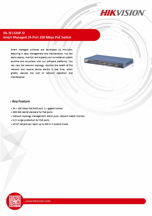
DS-3E1326P-SISmart Managed 24-Port 100 Mbps PoE SwitchSmart managed switches are developed by Hikvision,featuring in easy management and maintenance. You caneasily deploy, monitor and expand your surveillance systemanytime and anywhere with our software platforms. Youcan view the network topology, monitor the health of thenetwork and receive device alarms in real time, whichgreatly reduces the cost of network operation andmaintenance.Key Feature• 24 × 100 Mbps PoE RJ45 port, 2 × gigabit combo.• IEEE 802.3at/af standard for PoE ports.• Network topology management, alarm push, network health monitor.• 6 KV surge protection for PoE ports.• AF/AT camera can reach up to 300 m in extend mode.SpecificationModel DS-3E1326P-SINetwork Parameters Port Number 24 × 100 Mbps PoE RJ45 port, and 2 × gigabit comboPort Type RJ45 port, full duplex, MDI/MDI-X adaptiveStandardIEEE 802.3, IEEE 802.3u, IEEE 802.3x, IEEE 802.3ab, and IEEE802.3zHigh Priority Ports Ports 1 to 8Forwarding Mode Store-and-forward switchingWorking ModeStandard mode (default)Extend modeMAC Address Table 16 KSwitching Capacity 8.8 GbpsPacket ForwardingRate6.5472 MppsInternal Cache 4 MbitsPoE Power Supply PoE Standard IEEE 802.3af, IEEE 802.3atPoE Power PinEnd-span: 1/2(-), 3/6(+)Mid-span: 4/5(+), 7/8(-)8-pin power: 1/2(-), 3/6(+), 4/5(+), 7/8(-) PoE Port Ports 1 to 24Max. Port Power 30 WPoE Power Budget 370 WSoftware Function Device MaintenanceRemote upgrade, default parameters recovery, logs viewing,basic network parameters configuration, import and exportconfiguration, time syncPort Configuration Port rate configuration, slow control, and ports enabling Long Range Up to 300 m transmissionPoE ConfigurationPoE watchdog: Ports 1 to 24 auto detect and restart thecameras that do not respond.PoE enabling: SupportPort Rate-Limiting Rate-limiting for ingress and egress portsStorm Control Storm control of unknown unicast, multicast and broadcast Port Mirroring SupportLink Aggregation Static link aggregation supported for G1 and G2 portPort Isolation Ports in isolation group cannot communicate with each other. QoS WRR and SP scheduling and port priorityVLAN 4094 VLANsSTP STP and RSTP protocolsSNMPSNMPv1 and SNMPv2c supported for obtaining nodeinformation of the system and interfacesLLDPLLDP protocol supported for port configuration, globalconfiguration and neighbour discoveryGeneral Shell Metal material Net Weight 2.83 kg (6.24 lb)Gross Weight 3.33 kg (7.34 lb) Dimension (W × H × D)440 mm × 44 mm × 221 mm (17.32” × 1.73” × 8.70”) OperatingTemperature-10°C to 55°C (14°F to 131°F) Storage Temperature-40°C to 85°C (-40°F to 185°F) Operating Humidity5% to 95% (no condensation) Relative Humidity5% to 95% (no condensation) Power Supply100 VAC~240 VAC, 50/60 Hz, Max. 6.5 A Max. PowerConsumption400 W Power Consumption inIdle 5 WApprovalEMC FCC (47 CFR Part 15, Subpart B); CE-EMC (EN 55032: 2015, ENIEC 61000-3-2: 2019, EN 61000-3-3: 2013+A1: 2019, EN50130-4: 2011 +A1: 2014, EN 55035: 2017); IC (ICES-003: Issue 6); RCM (AS/NZS CISPR 32: 2015)Safety UL (UL 60950-1); CB (IEC 60950-1:2005, AMD1:2009, AMD2:2013, IEC 62368-1: 2014 (Second Edition); CE-LVD (EN60950-1: 2006 + A11: 2009 +A1: 2010+A12: 2011+A2: 2013, EN 62368-1: 2014+A11: 2017)ChemistryCE-RoHS (2011/65/EU); WEEE (2012/19/EU); Reach (Regulation (EC) No.1907/2006)⏹Typical Application⏹ Available ModelDS-3E1326P-SI⏹Physical Interface⏹Dimension (Unit: mm)。
4口百兆PoE交换机使用说明书

4口百兆PoE 交换机使用说明书V1.0.0浙江大华技术股份有限公司法律声明版权声明© 2017 浙江大华技术股份有限公司。
版权所有。
在未经浙江大华技术股份有限公司(下称“大华”)事先书面许可的情况下,任何人不能以任何形式复制、传递、分发或存储本文档中的任何内容。
本文档描述的产品中,可能包含大华及可能存在的第三人享有版权的软件。
除非获得相关权利人的许可,否则,任何人不能以任何形式对前述软件进行复制、分发、修改、摘录、反编译、反汇编、解密、反向工程、出租、转让、分许可等侵犯软件版权的行为。
商标声明●、、、是浙江大华技术股份有限公司的商标或注册商标。
●HDMI标识、HDMI和High-Definition Multimedia Interface 是HDMI LicensingLLC的商标或注册商标。
本产品已经获得HDMI Licensing LLC授权使用HDMI技术。
●VGA是IBM公司的商标。
●Windows标识和Windows是微软公司的商标或注册商标。
●在本文档中可能提及的其他商标或公司的名称,由其各自所有者拥有。
更新与修改为增强本产品的安全性、以及为您提供更好的用户体验,大华可能会通过软件自动更新方式对本产品进行改进,但大华无需提前通知且不承担任何责任。
大华保留随时修改本文档中任何信息的权利,修改的内容将会在本文档的新版本中加入,恕不另行通知。
产品部分功能在更新前后可能存在细微差异。
法律声明I前言概述本文档主要描述了4口百兆PoE交换机的产品特性和结构。
本说明书适用于以下产品型号:DH-S1500C-4ET2ET-DPWR符号约定在本文中可能出现下列标志,它们所代表的含义如下:表示能帮助您解决某个问题或节省您的时间。
表示是正文的附加信息,是对正文的强调和补充。
前言II重要安全须知下面是关于产品的正确使用方法、为预防危险、防止财产受到损失等内容,使用设备前请仔细阅读本说明书并在使用时严格遵守,阅读后请妥善保存说明书。
丰润达AI6016poe交换机说明书

丰润达AI6016poe交换机说明书丰润达自主研发设计出千兆上联AIPoE交换机AI6016,适合应用于100-300个监控节点的中型监控工程,以及100个监控节点以内的小微/中小监控工程。
千兆上联PoE交换机AI6016、AI6024,除去沿袭丰润达AIPoE 的基因外,更有惊艳的普惠价格,绝对是安防监控工程中性价比最高的PoE交换机之一了。
产品特点:千兆上联口,保证传输流畅稳定,16/24个百兆电口,1个千兆上联光电复用口,所有端口具备线速转发能力,保证稳定传输不丢包。
在监控工程中,NVR连接千兆上联口,下联可满载16/24个800万像素摄像头。
超大缓存设计,高清视频传输不卡顿。
采用1M超大缓存设计,是同档位其他品牌交换机的两倍。
保证满载16个800万像素高清监控不卡顿。
一键AIPoE模式,确保设备正常运行。
24小时自动检测受电端口设备,发现死机设备可立即断电重启设备,恢复PoE供电,无需工程维护人员亲赴现场,也不会错误重启其它正常运转的设备,大大提高了摄像机的在线率,减少了网络维护工作量及人工成本。
一键Extend模式,250米远距离传输。
由于监控环境的复杂,在接入布线和组网中通常会碰到网络传输距离不够的问题,各个摄像头终端到监控中心的距离不同,有的会几百米甚至更远。
丰润达千兆上联AIPoE交换机AI6016/AI6024具有延长功能设计,开启Extend模式时,1-8口数据传输最远可达250m,可替代延长器和部分光纤,扩展设备适用范围,节省项目成本。
(注:“250m 远距离传输”为丰润达实验室测试数据,实际传输距离会受网线质量、摄像头网口接收能力所影响。
)一键VLAN模式,隔离广播风暴,专为中型/中小型安防监控设计,支持一键切换VLAN模式,1-16/1-24口相互隔离。
模式开启时,可隔离广播风暴、组织ARP病毒、DHCP欺骗,轻松解决由广播风暴引起的高清监控卡顿、不流畅问题,并提升内网传输速率及安全性。
2.5Gbps以太网PoE交换机安装手册说明书

Enterprise Networking Solution安装手册2.5Gbps以太网PoE交换机声明Copyright © 2021 普联技术有限公司版权所有,保留所有权利未经普联技术有限公司明确书面许可,任何单位或个人不得擅自仿制、复制、誊抄或转译本手册部分或全部内容,且不得以营利为目的进行任何方式(电子、影印、录制等)的传播。
为普联技术有限公司注册商标。
本手册提及的所有商标,由各自所有人拥有。
本手册所提到的产品规格和资讯仅供参考,如有内容更新,恕不另行通知。
除非有特殊约定,本手册仅作为使用指导,所作陈述均不构成任何形式的担保。
I声明II相关文档 相关文档安装手册简介《安装手册》主要介绍了2.5Gbps以太网PoE交换机的硬件特性、安装方法以及在安装过程中应注意事项。
本手册包括以下章节:第1章:产品介绍。
简述交换机的基本功能特性并详细介绍外观信息。
第2章:产品安装。
指导交换机的硬件安装方法以及注意事项。
第3章:硬件连接。
指导交换机与其他设备之间的连接及注意事项。
附录A:技术参数规格。
说明:在安装设备之前及安装设备过程中为避免可能出现的设备损坏及人身伤害,请仔细阅读本手册相关内容。
阅读对象本手册适合下列人员阅读:网络工程师网络管理人员约定在本手册以下部分,如无特别说明,均以TL-SH1005PB为例介绍,所涉及的产品图片仅为示意说明,请以实际机型为准。
本手册采用了如下几种醒目标志来表示操作过程中应该注意的地方,这些标志的意III阅读对象目录第1章 目录第1章 产品介绍 —————————————011.1 产品简介 (01)1.2 产品外观 (01)第2章 产品安装 —————————————032.1 物品清单 (03)2.2 安装注意事项 (03)2.3 安装工具准备 (06)2.4 产品安装 (06)第3章 硬件连接 —————————————073.1 连接RJ45端口 (07)3.2 连接电源 (07)3.3 设备初始化 (08)附录A 技术参数规格 ———————————09IV目录2.5Gbps以太网PoE交换机安装手册01产品介绍第1章 产品介绍1.1 产品简介TL-SH1005PB是普联技术有限公司自主研发的2.5Gbps以太网PoE交换机。
海康威视经济型POE交换机产品手册说明书
经济型POE交换机产品简介DS-3E系列POE交换机支持5/8/16/24口百兆PoE电口,可通过网线直接供电,PoE自适应802.3af(15.4W)和802.3at(30W)标准,整机PoE最大输出功率为58/120/230/370W,通过普通的5类双绞线即可为AP、IP摄像头、IP电话等PoE受电设备同时传输电力和数据。
设备支持网络延长(EXTEND)模式,开启后,使用超五类及以上网线时,对应端口的数据传输和供电距离最远可达250米;PoE支持8芯供电技术,有效降低电源线路损耗;支持重要端口数据保障功能,对于重点区域的数据或视频,优先保证及传输;智能型支持VLAN、链路汇聚、QoS、STP防环、SNMP等智能管理功能,可减少项目施工难度和施工时间,最大程度的节省工程项目成本,保护用户投资。
整机全金属设计,结构坚固、使用方便,可靠性好,适用于园区、公安、楼宇等多种监控场景。
DS-3E0105P-EDS-3E0109P-E&DS-3E0109P-E(B)DS-3E0318P-EDS-3E0326P-EDS-3E1310P-EDS-3E1318P-EDS-3E1326P-E订货型号功能特性●支持802.3af/at PoE标准●支持PoE 8芯供电技术,降低网线电源损耗●支持重要端口数据保障●支持EXTEND模式,延长网线传输至250m●支持buffer优化,保证视频数据传输●支持VLAN配置(智能型支持)●支持端口汇聚(智能型支持)●支持STP、组播、端口镜像(智能型支持)●支持QoS(智能型支持)●支持SNMP网络管理(智能型支持)●支持WEB管理(智能型支持)●存储转发交换方式;●支持IEEE802.3、IEEE802.3u、IEEE802.3x网络标准●平均无故障时间MTBF≥10万小时;●全金属封闭结构;●桌面、机架式设计,安装简便技术参数非网管型硬件规格智能型硬件规格智能型软件规格组网应用DS-3E1318P-EDS-3E1318P-EDS-3E1318P-EDS-3E1318P-EDS-3E2528电视墙POE IPCPOE交换机汇聚交换机NVR客户端存储服务器监控组网示意图。
PoE交换机快速入门说明书
PoE交换机快速入门V1.011项目名称数量单位1 主机 1 台2* 电源线 1 根3* 电源适配器 1 个4* 橡胶脚垫 4 个5* 螺钉 4 个6* 挂耳 1 对7 用户资料 1 份备注:根据产品不同型号和不同版本,随箱附件可能有变动,请以实际为准。
*表示可选,仅部分款型随机附带。
2不同款型交换机外观会有所不同,具体请以实物为准。
2.1 前面板4口PoE交换机8口PoE交换机1.G1/SFP1状态指示灯2.G2状态指示灯3.电源状态指示灯4.整机PoE功率指示灯5.PoE端口状态指示灯6.优先级端口7.千兆以太网接口8.光模块接口9.PoE端口10.Link/Act状态指示灯11.百兆以太网接口2.2 后面板4口和8口PoE交换机16口和24口PoE交换机3不同款型指示灯颜色会有所不同,具体请以实物为准。
指示灯颜色描述POWER 绿色灭:交换机未通电常亮:交换机通电正常 PoE 绿色灭:PoE 端口未供电 常亮:PoE 端口正常供电 Link/Act 绿色灭:没有连接网络设备 常亮:连接到网络设备 闪烁:正在传输数据PoE-MAX 绿色/黄色灭:整机PoE 输出功率低于总功率的80%常亮:整机PoE 输出功率高于总功率的85%44.1 工具准备绝缘手套、螺丝刀、螺钉4.2 安装步骤4.2.1 桌面安装将脚垫粘贴到机壳底部四角对应的凹槽内,然后将交换机正置,放在足够大且干净平稳的桌面上。
4.2.2 壁挂式安装根据设备底部的定位孔位置在墙壁上固定两颗螺钉。
然后对准交换机的两个定位孔,把设备平稳地挂在螺钉上。
4.2.3 机架式安装1.检查机架的接地与平稳性,使用随机附带的螺钉将两个挂耳固定到交换机的两侧。
2.将交换机放置于机架内的适当位置,用螺钉(需自备)将挂耳固定到机架两侧的导槽上,确保交换机平稳地安装到机架上。
注:16口和24口PoE交换机支持桌面安装与机架式安装,4口和8口PoE交换机支持桌面安装和壁挂式安装。
10口工业级POE交换机说明书
10口工业级POE 交换机说明书【概述】10口POE 工业以太网交换机采用高强度IP40防护外壳,工业级EMC 设计,支持宽范围冗余电源输入(46~52V DC )以增加通讯网络的可靠性。
提供管理功能,可通过Web 浏览器、CLI 和SNMP 进行管理。
可同时支持8个端口15.4W 或4个端口30W ,总功率不能超过120W ,可以作为PSE 为其他设备供电;0~2个1000BASE SFP 接口,可以根据业务口需求灵活的进行光电组合。
可以为IEEE802.3 at /af 兼容的被供电设备进行供电,因此可以减少额外的布线成本。
【性能特点】非网管型POE 交换机特性支持IEEE802.3/802.3u/802.3ab/802.3 at /af 标准,存储转发交换方式支持8口带POE 功能10/100BASE-T(X) RJ45电口,支持Auto-Negotiation 技术,自动协商工作速率(10M/100M )和双工模式(半双工/全双工)支持0~2个1000 BASE SFP 接口,可适配1000M SFP 光模块(支持单模和多模)和1000M SFP 电口模块(支持双绞线传输) 支持广播风暴抑制功能采用高强度IP40外壳及工业级EMC 设计支持冗余宽电压46~52V DC 电源输入,满载功耗145W-40~60℃工作温度范围 网管型POE 交换机特性支持Web 、CLI 和SNMP 三种管理方式,CLI 支持Telnet 和console 登录支持POE WEB 管理功能支持存储转发机制支持端口常用特性设置,如端口使能、自适应或强制、流控等支持端口镜像,用于在线调试、监控网络数据状态支持端口带宽限制功能,优化带宽利用支持端口聚合功能,用于扩展网络带宽,提高网络传输效率支持端口优先级QoS 设置,提高网络服务质量支持端口MAC 地址学习和数据统计功能支持802.1Q VLAN 设置,有效控制广播域支持单播/多播MAC 地址管理支持静态IGMP 多播过滤,用于过滤工业以太网协议中的多播流量支持SNMP V1/V2C/V3使不同层次的网络管理均具有稳定性支持RSTP ,避免报文在环路网络中的增生和无限循环支持即插即用的冗余自愈以太环网技术(全负载下故障恢复时间<20ms ),支持环网单环、相切和相交三种环网模式支持继电器告警输出支持全局网络系统管理【包装清单】初次使用交换机时,请首先检查包装随机的附件是否齐全。
JetNet 3705 工业 PoE 交换机使用说明说明书
51OverviewFour 10/100 TX Power Over Ethernet ports and one 10/100 TX uplink port30KM for Single-Mode / 2KM for Multi-Mode Fiber Uplink Port 15.4W Full Power Delivery per PoE Port Relay Alarm for Port FailureTerminal Block Power Input for Industrial Application. DC Jack Power Input for External Power Adapter End-Point PoE Architecture Easy Configuration by DIP SwitchDIN-Rail/ Wall-mounting and Desktop Installation-20~70oC operating temperature for hazardous environment application (JetNet 3705-w -40~70oC)JetNet 3705, the winner of Best Choice of Computex Taipei 2007 Award, is an I ndustrial PoE switch delivers powers over UTP/STP cable not only yield a cost-effective and space-saving network, but also improve power utilization and centralize power management. The JetNet 3705 is equipped with 4 PoE injector switch ports, delivers up to 15.4 watts in each port, and one 10/100Base TX Up-link port forwarding data to the remote end. The JetNet 3705 conforms to I EEE 802.3af Power over Ethernet (PoE) standard. The Power over Ethernet technology can power up PoE enabled powered devices in full capability, e.g. IP surveillance camera, wireless Access Point,VoI P phone set, POS system, industrial sensors, controllers and security card reader. By connecting an external DC 48V power supply, JetNet 3705 is able to perform power and data transmission to send/receive over the same UTP/STP cable in each of the four PoE ports.To meet the requirements of operating under harsh environment, JetNet 3705 uses a robust aluminum case, offers IP31 protection, and supports alarm relay output. The JetNet 3705 provides standard industrial terminal block for the power and alarm relay contact output to alarm any port malfunction or power failure. For the user's convenience, it also provides a DC jack for the traditional AC/DC power adapter.Korenix JetNet 3705 is an I ndustrial 4-port PoE injector Switch with one 10/100TX Up-link port. The PoE port provides 10/100Mbps Ethernet speed and is conformed to IEEE802.3af PSE standard with 15.4W full power forwarding ability.To meet requirements of Industrial application, JetNet 3705 equipped 2 power inputs and provides real-time relay alarm mechanism for the power or port eventalert. To operate correctly in a harsh environment, JetNet 3705 adopts aluminum case with excellent heat radiation, and the self-diagnostic LED display including power, port link and PoE power status on the top of the switch for real time monitoring.The JetNet 3705 is compliant with I EEE802.3af standard plus over current and short current protections to avoid damaging other powered device.Industrial 5-port Unmanaged PoE SwitchJetNet 3705 / 3705-w48V Power Over Ethernet SystemRoHSIndustrial PoE SwitchIndustrial PoE SwitchIP67/68 Ethernet Switch RackmountManaged Switch Gigabit Switch Redundant Switch Entry-Level Switch Networking ComputerCommunication Computer Ethernet I/O Server Serial Device Server Media Converter MultiportSerial Card SFP Module Din Rail Power Supply52High Layer SwitchMonitor & Control CenterData & DC48VPoE IP Camera Wireless APCeiling Type PoE IP CameraIP Surveillance AppicationOutdoor2 x DC48V InputAlarm Relay OutputJetNet 3705Dimensions (Unit –mm)ApplicationSpecificationOrdering InformationJetNet 3705 Industrial 5-port Unmanaged PoE Switch Includes:JetNet 3705Wall mount panel kitsQuick Installation GuideCD User manual Power RequirementsSystem PowerInput Voltage:48VDC or -48VDC, dual power inputs in terminal block connectionAC /DC Power Adapter DC 48V/1.6A (option)One DC jack for AC/DC power adapterReverse Polarity Protection: PresentPower Consumption:6.5Watts without PD loading70Watts with PD full loadingMechanicalInstallation: DIN-Rail mount or Wall MountCase: IP-31 grade aluminum metal caseDimension:33.8 mm (H) x 164.8 mm(W) x 108 mm (D) EnvironmentalOperating Temperature: -20 ~70C(JetNet 3705-w -40~70C)Operating Humidity: 0% ~ 95%, (non-condensing) Storage Temperature: -40 ~ 80 CStorage Humidity: 0%~ 95%, (non-condensing) Regulatory ApprovalsHi-Pot : 1.2KV testing passed on port to powerEMI: FCC Class A, CE/EN55022 Class AEMS:EN61000-4-2, EN61000-4-3, EN61000-4-4, EN61000-4-5, EN61000-4-6, EN61000-4-8, EN61000-4-11Safety: CE/EN60950Shock: IEC60068-2-27Vibration: IEC60068-2-6Free Fall: IEC60068-2-32MTBF: 517,810 Hours, MIL-HDBK-217F GB standard Warranty: 5 yearsTechnologyStandard:IEEE802.3 10Base-TIEEE802.3u 100Base-TXIEEE802.3af Power over EthernetIEEE802.3x flow controlSwitch Technology: Store and forward technology andwith 3.2Gbps internal switch fabric.Aggregate System Throughput: 1.49MppsMAC Address: 1K MAC address TablePacket Buffer: 512KbitsPower over Ethernet port:Port 1~4, with 15.4w full power forwarding abilityRJ-45 pin assignment: TX (3,6), RX (1,2), V+ (4,5), V-(7,8)PoE output voltage: DC 44~57VInterfaceNumber of Ports: 4 x 10/100 Base-TX with Power overEthernet injector ,Auto MDI/MDI-X, Auto-Negotiation1 x 10/100 Base-TX uplink portConnectors:10/100 Base-TX: RJ-45Power/Relay: 6-Pin Terminal BlockDC-JackCables:10Base-T: 4-pair UTP/STP Cat. 3, 4, 5 cable,EIA/TIA-568 100-ohm(100m)100Base-TX: 4-pair UTP/STP Cat. 5 cable,EIA/TIA-568 100-ohm(100m)Port Alarm DIP Switch:DIP 1~5: Enable (On) or disable (Off) port link downalarm from port 1 to port 5.DIP 6: Enable (On) or disable (Off) power alarm.Diagnostic LED:Power x 3 (Green), Fault x 1(Red)PoE x 4(Green),Link/Activity x 5 (Green on/GreenBlinking)@100Mbps, (Yellow on/Yellow Blinking)@10MbpsOptional AccessoriesDC 48V Din-Rail Power: DR-75-48DC 48V Din-Rail Power: MDR-100-4853。
- 1、下载文档前请自行甄别文档内容的完整性,平台不提供额外的编辑、内容补充、找答案等附加服务。
- 2、"仅部分预览"的文档,不可在线预览部分如存在完整性等问题,可反馈申请退款(可完整预览的文档不适用该条件!)。
- 3、如文档侵犯您的权益,请联系客服反馈,我们会尽快为您处理(人工客服工作时间:9:00-18:30)。
PSE5000系列 POE供电以太网交换机
Quick Installation Guide
Power over Ethernet Switch PSE5000系列
PSE6000系列
用户手册V1.02
User’s Manual
1.概述
PSE5000及PSE6000系列POE供电交换机,是非网管以太网供电交换,使用时无需配置,接上电源后即可使用。
此系列POE供电交换机提供5个10/100Base-TX或1000Base-TX自适应端口,1个为Uplink端口。
2.装箱清单
小心打开包装盒,包装盒内应有以下配件:
PSE5000或PSE6000系列以太网交换机 *1台;
专用电源线(常规为国标电源线) *1条;
快速设定手册 *1本;
保修卡/合格证 *1张;
如果发现有配件损坏或者短缺的情况,请及时和当地经销商或销售方联系。
PSE5000系列产品型号为:
PSE5302:5埠百兆交换机,2埠 PoE(其中第4、5口支持POE)
PSE5604:5埠百兆交换机,4埠 PoE(其中第2、3、4、5口支持POE)
PSE6000系列产品型号为:
PSE6504G:5埠千兆交换机,4埠 PoE(其中第2、3、4、5口支持POE)
3.产品外观
① PSE5302 POE供电交换机铭板图
②PSE5604 POE供电交换机铭板图
③PSE6504G POE供电交换机铭板图
4. LED指示灯示意说明
安装应用示意图(PSE5604 & PSE6504G)
安装应用示意图(PSE5302)
5.安装注意事项
为保证交换机正常工作和延长使用寿命,请遵从以下的注意事项:
①交换机只在室内使用,请将交换机置于通风干燥处;
②交换机AC电源线需接地
③交换机的接口电缆要求在室内走线,禁止户外走线,以防止因雷电产生的过电压、过电
流损坏交换机;
④请不要将交换机放在不稳定的箱子或桌子上,一旦跌落,会对交换机造成严重损害;当
选择壁挂安装时,应将交换机及电源适配器固定好(电源部分在上),避免跌落;
⑤在交换机周围应预留足够的空间(大于10cm),以便于设备正常散热;
⑥请不要在交换机上放置重物;
⑦请使用随产品附带的电源适配器,严禁使用其它非配套产品。
电网的电压必须满足专用
电源适配器的输入的电压范围。
6.连接线缆
①将网线的一端连接到交换机的端口,另一端连接到计算机或其他网络设备。
说明:请先把所有要连接的计算机或网络设备均连接到交换机之后,再进
行电源适配器的连接。
②请将随机附带的电源线一端插到交换机后面板的电源适配器
插口上,另一端插到外部的供电交流电源插座上。
③将连接到交换机的设备通上电,连接端口相对应的指示灯将会点
亮,此时安装完成。
7.规格参数。