派利斯探头使用说明书
取样探头 222.15 17 20 21 31 35 安装及使用说明书

取样探头222.15/17/20/21/31/35安装及使用说明书BC460017, 07/2017 Art. Nr. 90 31 059Bühler Technologies GmbH, Harkortstr. 29, D-40880 RatingenTel. +49 (0) 21 02 / 49 89-0, Fax. +49 (0) 21 02 / 49 89-20AP000005请在安装和使用前仔细阅读此手册。
敬请特别注意所有安全守则,以避免不必要的意外伤害事故。
Bühler Technologies GmbH /德国比勒科技有限责任公司对由不当操作以及在未授权情况下擅自改动机器设备所引起的后果不承担任何责任。
目录页1概述 (4)2重要注意事项 (4)2.1安全注意事项概述 (5)3铭片说明 (6)4产品说明 (6)4.1概述 (6)4.2发货内容 (6)5运输及存储要求 (7)6安装及线路连接 (7)6.1安装 (7)6.2探管的连接 (8)6.2.1样气管的连接 (9)6.2.2校正气体管的连接(可选) (9)6.3反吹和反吹气罐的连接(适用于 GAS 222.21, 31 和 35) (9)6.4电子线路连接 (10)6.4.1型号 GAS 222.15 / GAS 222.17 (10)6.4.2型号 GAS 222.20, 21, 31, 35 (10)6.4.3加热反吹气罐(可选) (11)6.4.4加热扩展件(可选) (11)7操作与维护 (11)7.1安全条款 (11)7.2操作前请检查 (12)7.3探头GAS 222.20, 21, 31, 35 上控制器的功能 (13)7.3.1所有控制器的功能 (13)7.3.2加热扩展件的内置控制器的更多功能(可选) (13)7.3.3内置反吹控制器的功能 (13)7.3.4附加PCB电路板用于电磁阀和限位开关(可选电磁阀控制板) (13)7.4滤芯的维护: (13)7.4.1带顺流过滤器的探头GAS 222.15 (13)7.4.2使用玻璃纤维滤芯的顺流过滤器 (14)7.4.3带顺流过滤器的探头GAS 222.17, 20 和 21 (14)7.4.4带直插过滤器的探头GAS 222.21, 31 和 35 (15)7.5工艺管道中直插过滤器的反吹 (16)7.5.1手动反吹 (16)7.5.2自动反吹 (16)7.5.3内置反吹控制器 (17)7.6控制器的设置 (18)7.6.1菜单选项 (18)7.6.2操作原则详述 (19)7.6.3菜单功能说明 (20)7.6.3.1主菜单 (20)7.6.3.2探头控制器的子菜单(Display: Prob) (21)7.6.3.3加热扩展件控制器的主菜单(display: Adon) (可选) (21)7.6.3.4反吹控制器的子菜单(display: bbc) (可选) (22)8故障及故障排除 (23)8.1备件 (24)9维修及报废处理 (24)9.1报废处理 (24)10制图,证明,数据表 (25)10.1接线图 GAS 222.15/17 (25)10.2接线图 GAS 222.20, 21, 31, 35 (26)10.3加热气罐的连线图 (27)10.4附加文件 (27)1 概述GAS 222.xx系列探头设计安装于气体分析系统内部。
派利斯公司用户手册

4 16=20-4; 5 根据用户需要而定; 6 根据仪表参数而定,现场不能更改;
¾ 探头的安装 ¾ 和各仪表元件之间的正确接线 2) 探头的安装(参见涡流探头的安装)
派利斯电子(北京)有限公司产品用户手册
3)正确接线 (参照 TM202 现场接线图)
TM0200; or PLC, Remore
DCS
Reset
延长电缆
POW
前置器 COM
SIG
8mm涡流探头 转子
TO ALERT
SPAN
1.取下监测表角上的四个螺钉。 2.连接前置器、延长电缆和涡流传感器,使传感器接近被测物体, 保持涡流探头与被测物
体的静态间距为 0.8mm. 3.卸下前面板上的四个螺钉。. 4.在振动台静态时,调节 “ZERO”钮 直到 “4-20mA ”输出显示 4.00mA. 5.将振动台的振动调至最大调节检 测右下脚的“SPAN”, 直到“ 4-20mA ”输出显示为
报警值电流读数=4+16×12/50=7.84mA 连锁值电流读数=4+16×25/50=12.0mA
本指南适用于TM202、TM302。
对于TM表的现场调试仅限于设置 零位(Zero)、报警(Alert)、连锁(Danger)值 的更改与设定,其它操作必须经过派利斯公司同意方可进行! 调试步骤如下: 1. 正确接线; 2. 卸下 TM 表上的小标牌(印有技术参数的白色小标牌); 3. 按照下图对照进行操作:
派利斯电子(北京)有限公司产品用户手册
6、TM201 单通道振动保护表探头安装指南
1) 安装步骤: TM201 单通道保护表的安装一般分两大步骤:
奥立木(Olympus)腺管超声下探头(EBUS)BF-UC190F腺管镜清洗和消毒检查表说明书

Endobronchial Ultrasound (EBUS)BF-UC190F Endoscopes Cleaning and Disinfection ChecklistEndobronchial Ultrasound (EBUS) EndoscopesCleaning and Disinfection ChecklistThis checklist is designed for use solely as a customer educational tool and is not intended to replace or in any way modify the Olympus instruction manual/reprocessing manual. Be sure to follow the detailed steps outlined in the reprocessing manual that was included with your Olympus equipment when purchased. While Olympus' training may be used in support of a facility's overall competency program, it shall not constitute certification of the facility's CDS protocol. Olympus shall in no event be held responsible for a facility's proper performance of CDS protocol nor for a facility staying current with ongoing CDS instructional changes and corresponding training updates. Facility owners of Olympus equipment are fully responsible for complying with industry CDS standards and manufacturer's proper use and CDS instructions.Endoscope Models: Check each model reviewed during this session.BF-UC190FFacility NameDateInstructor NameTitleSignatureSignatureComments:2. Turn the inserted brush once for one full revolution.3. Pull the brush out and clean the brush bristles in thedetergent solution.4. Repeat until no debris is observed on the brush.6. Turn the inserted brush once for one full revolution.7. Pull the brush out and clean the brush bristles in thedetergent solution.Remove endoscope from detergent solution.Comments:Comments:Using the syringe, flush the front balloon grove at the distal end of the endoscope with 30mls of the disinfectant solution. Confirm no airWipe all external surfaces of the endoscope and suction cleaningadapter using your gloved finger or sterile lint free cloths.Cover the basin with a tight-fitting lid to minimize exposure to Comments:Comments:Comments:Comments:。
飞利浦监护仪(20等)使用说明书-2
切断电源1基本操作切断电源开机/待机开关并不会切断监护仪的交流电源。
要切断电源,请拔掉电源电缆。
断电之后的监护如果监护仪断电时间少于一分钟,则监护会继续进行,所有当前活动的设定保持不变。
如果监护仪断电时间超过一分钟,则监护仪的反应取决于您的配置。
如果将自动默认设为是,当恢复供电时,会载入默认设定简档。
如果将自动默认设为否,只要能够在 48 小时之内恢复供电,就会保留所有当前生效的设定。
自动默认设定在“配置模式”中完成。
联网监护可以将监护仪与联网的信息中心相连接,这可通过使用任何一款选配接口完成:•标准有线 LAN•无线 LAN•IntelliVue 设备遥测系统 (IIT)警告请不要将病人监护仪连接到标准医院网络。
此外,如果 IntelliVue X2 或 MP5 配备有 IIT,并在“信息中心”申报为遥测设备,当其与主监护仪配对后就可以确保数据连续性。
断开与主监护仪的连接后,它可在转运期间继续监护病人并向信息中心中的相同屏区提供连续的数据。
(请参见第 247 页上的“为一个病人指定两个设备”。
)如果监护仪连接到网络,则有一个网络符号显示在左上角,在病床标名旁边。
请参见有关“护理组”、监护设备和网络技术信息的细节。
♦MP20/MP30/MP40/MP50 - 选择监护仪信息行进入设定菜单,然后选择床头信息。
♦MP60/MP70/MP80/MP90 - 在监护仪信息行中选择病床标名。
请注意与有线网络上的监护仪相比,无线网络连接的监护仪在有些网络功能方面可能受到限制。
如果使用标准医院网络,将无法保证打印功能和数据导出正常运行。
使用远程应用程序如果监护仪和“飞利浦应用项目服务器”相连,则可远程访问托管在应用服务器上的应用项目,并在病床旁监护仪屏幕上显示它们和进行操作。
应用服务器提供门户技术,以允许通过 Web 浏览器、终端仿真程序或客户机应用程序来访问信息。
可访问的应用项目取决于应用服务器的配置:有关详细信息,请参见设备文档。
Pepperl+Fuchs NCN4-V3-N0 型号 4mm 非磨砂型非平摆式感应传感器说明书
16-12-05 12:10D a t e o f i s s u e : 2017-01-02087489_e n g .x m lInstructionManual electrical apparatus for hazardous areas Device category 1Gfor use in hazardous areas with gas, vapour and mist EC-T ype Examination CertificateCE marking ATEX marking ¬ II 1G Ex ia IIC T6…T1 G aThe Ex-related marking can also be printed on the enclosed label.Standards EN 60079-0:2012+A11:2013 EN 60079-11:2012 Ignition protection "Intrinsic safety"Use is restricted to the following stated conditions Appropriate typeNCN4-V3-N0...Effective internal inductivity C i ≤ 100 nF ; a cable length of 10 m is considered.Effective internal inductance L i≤ 100 µH ; a cable length of 10 m is considered.G eneralThe apparatus has to be operated according to the appropriate data in the data sheet and in this instruction manual. The EU-type examination certificate has to beobserved. The special conditions must be adhered to! Directive 94/9/EC and there-fore the EC-type-examination certificates generally apply only to the use of electrical apparatus under atmospheric conditions. The device has been checked for suitabil-ity for use at ambient temperatures of >60°C by the named certification authority. The surface temperature of the device remains within the required limits. If the equip-ment is not used under atmospheric conditions, a reduction of the permissible mini-mum ignition energies may have to be taken into consideration.Ambient temperatureDetails of the correlation between the type of circuit connected, the maximum per-missible ambient temperature, the temperature class, and the effective internal reac-tance values can be found on the EC-type examination certificate. Note: Use the temperature table for category 1 The 20 % reduction in accordance with EN 1127-1 has already been applied to the temperature table for category 1.Installation, commissioningLaws and/or regulations and standards governing the use or intended usage goal must be observed. The intrinsic safety is only assured in connection with an appro-priate related apparatus and according to the proof of intrinsic safety. The associated apparatus must satisfy the requirements of category ia.Due to the possible danger of ignition, which can arise due to faults and/or transient currents in the equipotential bonding system, galvanic isolation of the power supply and signal circuit is preferable. Associated apparatus without electrical isolation must only be used if the appropriate requirements of IEC 60079-14 are met. Install the device in such a way that the resin surface is not exposed to mechanical hazards. If the Ex-related marking is printed only on the supplied label, then this must be attached in the immediate vicinity of the sensor. The sticking surface for the label must be clean and free from grease. The attached label must be legible and indeli-ble, including in the event of possible chemical corrosion.Maintenance No changes can be made to apparatus, which are operated in hazardous areas.Repairs to these apparatus are not possible.Special conditionsThe connecting parts of the sensor must be set up in such a way that degree of pro-tection IP20, in accordance with lEC 60529, is achieved as a minimum.Protection from mechanical dangerWhen using the device in a temperature range of -60 °C to -20 °C, protect the sensor against the effects of impact by installing an additional enclosure. The information regarding the minimum ambient temperature for the sensor as provided in the datasheet must also be observed.Electrostatic chargeWhen used in group IIC non-permissible electrostatic charges should be avoided on the plastic housing parts. Information on electrostatic hazards can be found in the technical specification IEC/TS 60079-32-1. Additional requirements for gas group IIC. Avoid electrostatic charges that can cause electrostatic discharge when install-ing or operating the device.R e l e a s e d a t e : 2016-12-05 12:10D a t e o f i s s u e : 2017-01-02087489_e n g .x m lInstructionManual electrical apparatus for hazardous areas Device category 2Gfor use in hazardous areas with gas, vapour and mist EC-T ype Examination CertificateCE marking ATEX marking¬ II 1G Ex ia IIC T6…T1 G aThe Ex-related marking can also be printed on the enclosed label.Standards EN 60079-0:2012+A11:2013, EN 60079-11:2012Ignition protection "Intrinsic safety"Use is restricted to the following stated conditions Appropriate typeNCN4-V3-N0...Effective internal inductivity C i≤ 100 nF ; a cable length of 10 m is considered.Effective internal inductance L i ≤ 100 µH ; a cable length of 10 m is considered.G eneralThe apparatus has to be operated according to the appropriate data in the data sheet and in this instruction manual. The EU-type examination certificate has to beobserved. The special conditions must be adhered to! Directive 94/9/EC and there-fore the EC-type-examination certificates generally apply only to the use of electrical apparatus under atmospheric conditions. The device has been checked for suitabil-ity for use at ambient temperatures of >60°C by the named certification authority. The surface temperature of the device remains within the required limits. If the equip-ment is not used under atmospheric conditions, a reduction of the permissible mini-mum ignition energies may have to be taken into consideration.Maximum permissible ambient temperature T amb Details of the correlation between the type of circuit connected, the maximum per-missible ambient temperature, the temperature class, and the effective internal reac-tance values can be found on the EC-type examination certificate.Installation, commissioningLaws and/or regulations and standards governing the use or intended usage goal must be observed. The intrinsic safety is only assured in connection with an appro-priate related apparatus and according to the proof of intrinsic safety. Install the device in such a way that the resin surface is not exposed to mechanical hazards. If the Ex-related marking is printed only on the supplied label, then this must be attached in the immediate vicinity of the sensor. The sticking surface for the label must be clean and free from grease. The attached label must be legible and indeli-ble, including in the event of possible chemical corrosion.Maintenance No changes can be made to apparatus, which are operated in hazardous areas.Repairs to these apparatus are not possible.Special conditionsThe connecting parts of the sensor must be set up in such a way that degree of pro-tection IP20, in accordance with lEC 60529, is achieved as a minimum.Protection from mechanical dangerWhen using the device in a temperature range of -60 °C to -20 °C, protect the sensor against the effects of impact by installing an additional enclosure. The information regarding the minimum ambient temperature for the sensor as provided in the datasheet must also be observed.16-12-05 12:10D a t e o f i s s u e : 2017-01-02087489_e n g .x m lInstructionManual electrical apparatus for hazardous areas Device category 1Dfor use in hazardous areas with combustible dust EC-T ype Examination CertificateCE marking ATEX marking ¬ II 1D Ex ia IIIC T135°C DaThe Ex-related marking can also be printed on the enclosed label.Standards EN 60079-0:2012+A11:2013 EN 60079-11:2012Ignition protection "Intrinsic safety" Use is restricted to the following stated condi-tionsAppropriate typeNCN4-V3-N0...Effective internal inductivity C i ≤ 100 nF ; a cable length of 10 m is considered.Effective internal inductance L i≤ 100 µH ; a cable length of 10 m is considered.G eneralThe apparatus has to be operated according to the appropriate data in the data sheet and in this instruction manual. The EU-type examination certificate has to beobserved. The special conditions must be adhered to! The ATEX directive and there-fore the EU-type examination certificates are in general only applicable to the use of electrical apparatus operating at atmospheric conditions.The use in ambient temperatures of > 60 °C was tested with regard to hot surfaces by the mentioned certification authority.If the equipment is not used under atmospheric conditions, a reduction of the permis-sible minimum ignition energies may have to be taken into consideration.Permissible ambient temperature rangeDetails of the correlation between the type of circuit connected, the maximum per-missible ambient temperature, the surface temperature, and the effective internal reactance values can be found on the EC-type-examination certificate. The maxi-mum permissible ambient temperature of the data sheet must be noted, in addition, the lower of the two values must be maintained.Installation, commissioningLaws and/or regulations and standards governing the use or intended usage goal must be observed. The intrinsic safety is only assured in connection with an appro-priate related apparatus and according to the proof of intrinsic safety. If the Ex-related marking is printed only on the supplied label, then this must be attached in the imme-diate vicinity of the sensor. The sticking surface for the label must be clean and free from grease. The attached label must be legible and indelible, including in the event of possible chemical corrosion. Install the device in such a way that the resin surface is not exposed to mechanical hazards.Maintenance No changes can be made to apparatus, which are operated in hazardous areas.Repairs to these apparatus are not possible.Special conditionsThe connecting parts of the sensor must be set up in such a way that degree of pro-tection IP20, in accordance with lEC 60529, is achieved as a minimum.Protection from mechanical dangerWhen using the device in a temperature range of -60 °C to -20 °C, protect the sensor against the effects of impact by installing an additional enclosure. The information regarding the minimum ambient temperature for the sensor as provided in the datasheet must also be observed.Electrostatic chargeThe connection cables are to be laid in accordance with EN 50281-1-2 and must not normally be subjected to chaffing during use. Do not attach the nameplate provided in areas where electrostatic charge can build up.。
派利斯传感器
派利斯传感器TM0793V-M-S
速度传感器(转接螺丝 1/4-28” →M6×1) 本安防爆认证
派利斯传感器TM0793V-E 派利斯传感器TM0793V-E-S
速度传感器(转接螺丝 1/4-28” →1/4-28”) 本安防爆认证
附件:
. TM079VD 最大
派利斯传感器
出接口:
A:电源 (红) B:COM (白)
指南
垂直安装低频速度传感器
派利斯传感器79VD-H-AX-BX
AX: 灵敏度 : 速度: 40 mV/mm/s (1000mV/in/sec), : 位移: 4.0m BX: 安装 B0:3/4” NPT : M20×1.5
附件
716: 安装螺纹 M20×1.5
派利斯传感器TM0717:
安装TM079VD
附件:
(标准电缆长为 5 米, XX = 05) TM0702-XX: MIL铝插头, 带 XX 米电缆,直径6.35mm。< 120 C (250 F) TM0703-XX: 密封型插头,带 XX 米电缆, 直径6.35mm。 < 120 C (250 F) TM0704-XX: MIL不锈钢插头, 带 XX 米铠装电缆, 直径4.83mm 。 < 150 C (300 F) TM0705-XX: 横向MIL插头, 带 XX 米电缆,直径6.35mm。< 120 C (250 F)
温度区间:-50 C~+120 C
o o
防护等级:IP67
重量:90 克 外壳材料:不锈钢 安装孔经:1/4-28UNF 安装力矩:29N*M
连接
A:电源(红色电缆) B:公共端(白色电缆) COM:屏蔽层
定货指南
Pepperl+Fuchs UB500-F42S-E5-V15 超声探头产品说明说明书
Ultrasonic sensor UB500-F42S-E5-V15R e l e a s e d a t e : 2016-02-26 11:35D a t e o f i s s u e : 2016-02-26133981_e n g .x m lFunctional DescriptionThe sensor may be completely parameterised via two keys on the side panel of the housing. As a special feature provided by this sensor, the ultrasound beam width may be adapted to the environmental conditions at the place of operation of the sen-sor.Specifying the switching points:When specifying the switching points, the user determines at which points the switching output changes its state. The order of the switching points A1 > A2, or A1< A2 also determines the direction of action (i.e. normally-closed/normally-open con-tact function).DimensionsElectrical ConnectionPinoutAccessoriesMH 04-3505Mounting aid for FP and F42 sensors MHW 11Mounting brackets for sensorsV15-G-2M-PVCFemale cordset, M12, 5-pin, PVC cable Membrane keysLED window7.552.515.55.2101053415M 12x 1806580651634A 1A2T E A C H I NM O D ES E TStandard symbol/Connections:(version E5, pnp)Program inputSync. input Switch output Wire colors in accordance with EN 60947-5-2.+ U B1- U B2435(BN)(WH)(GY)(BK)(BU)UConnector V1523145Additional InformationProgrammable operation modesObject distance1. Switching point modeN. C.A2N. O.A1Object-presence A1, A23. Hysteresis modeN. C.A2 > A1N. O.A1 > A2Detection-limit2. Window modeN. O.A2 > A1N. C.A1> A2Note:means: cover transducer surface with your hand, while teaching the switching point.If A1 = A2, the output works like A2 > A1Unusable areaA1A2A1A2A1A2A1A2A2A1R e l e a s e d a t e : 2016-02-26 11:35D a t e o f i s s u e : 2016-02-26133981_e n g .x m lThe A2 switching point is specified via the A2 key, analogous to the description above.Alternatively, the switching points may also be specified electrically via the learn input. To specify the A1 switching point, the learn input must be connected to-U B ; to specify the A2 switching point, it must be connected to +U B . Specified values are saved upon the disconnection from the learn input.Switching points may only be specified directly after Power on. A time lock secures the adjusted switching points against unin-tended modification 5 minutes after the last keypress. To modify the switching points later, the user may specify the desired values only after a new Power On.Proceed as follows to parameterise the output function and the ultrasound beam width:Press the A1 key during Power on and hold down the key for another second to ensure that the sensor starts the two-step pa-rameterisation of the operating modes.Step 1, parameterisation of the output functionThe output function parameterised last is displayed. All output functions available may be selected via consecutive, brief strokes of the A2 key. These strokes are visualised via short flashes of the green LED.sor returns to normal mode. Step 2 may be initiated by briefly pressing the A1 key (parameterisation of the ultrasound beam width).Step 2, parameterisation of the ultrasound beam widthIn the near range, via Step 2, the ultrasound beam width may be adapted to the requirements of the corresponding application.The beam width parameterised last is displayed first. Available beam width settings may be selected via consecutive, brief strokes of the A2 key. These strokes are visualised via the flash sequence of the red LED.sor returns to normal mode. Briefly press the A1 key to return to Step 1 (parameterisation of the output function).If the parameterisation mode is not terminated within 5 minutes after last keypress (by holding down the A1 key for 2 seconds),the sensor aborts this mode without modifying the settings.SynchronisationThe sensor has a synchronisation port to suppress mutual influencing. If this port has not been connected, the sensor works at an internally generated cycle rate. Several sensors may be synchronised via the following options.Specifying the A1 switching point by pressing the A1 keyHolding down the A1key > 2 secondsThe sensor switches to learn mode and the user may specify the A1 switching pointPositioning the target object at the desired distance The yellow LED of the sensor flashes fast to indicate that the target object has been recognised. The red LED flashes if the object has not been recognised.Briefly pressing the A1 keyThe sensor terminates the specification of the A1switching point and saves it as a non-volatile value. The specified value is invalid if the object is uncertain (i.e. the red LED lights up at irregular intervals). The learn mode is exited.R e l e a s e d a t e : 2016-02-26 11:35D a t e o f i s s u e : 2016-02-26133981_e n g .x m lExternal synchronisation:The sensor may be synchronised via the external application of a square wave voltage. A synchronisation pulse on the syn-chronisation input initiates a measuring cycle. The pulse width must be greater than 100 µs. The measuring cycle is started with the falling edge. A low level > 1 s or an open synchronisation input initiate the transition to normal sensor mode. A high level on the synchronisation input deactivates the sensor.Two modes are possible:- Several sensors are controlled via the same synchronisation signal. The sensors work in common mode.- The synchronisation pulses are forwarded at cyclic intervals to respectively one single sensor. The sensors work in multiplex mode.Self-synchronisation:The synchronisation ports of up to 5 sensors suitable for self-synchronisation are connected to each other. These sensors work in multiplex mode after Power on. The On delay increases depending on the number of sensors to be synchronised. While the learn mode is active, no synchronisation is possible (and vice-versa). To specify the switching points, the sensors must be op-erated in non-synchronised mode.Note:If the synchronisation option is not used, the synchronisation input must be connected to ground (0V) or the sensor must be operated with a (4-pole) V1 connecting cable.。
派利斯中文使用手册
派利斯电子(北京)有限公司用户手册TM系列振动变送保护表安装操作维护TM-CAT-CHI-5.3-8815 COPY RIGHT PROVIBTECH 2008目录TM系列振动变送保护表的介绍 (2)I. 旋转机械监测和保护的发展 (2)II. 新功能 (2)III. 通用特点 (2)IV. TM 系列振动变送保护表选项 (3)TM101 机壳振动速度、加速度、位移变送保护表 (4)I. 概述 (4)II. TM101 振动变送保护表的技术参数 (4)III.订货选项. (5)IV.现场接线图 (7)V.现场报警调试 (8)VI. 现场操作 (9)VII. 4-20mA 标定(仅专业工程师操作) (10)TM系列振动变送保护表的介绍I. 旋转机械监测和保护的发展旋转机械监测的概念是二战以后由军方实验室推广而来,研究表明机械的故障严重影响生产,振动保护和状态监测的研究从50年代初至今已经得到完善的发展。
精确的监测旋转机械的运行状态主要有如下参量,轴承的径向振动、轴向位移、胀差和壳振,对于进一步的机械诊断,键相也是一个重要的测量参量。
典型的振动保护系统是由传感器和监测仪表组成的,传感器可分为趋进式涡流探头和测量绝对振动的加速度探头。
监测仪表将显示位移、速度、加速度单位。
由于集成电路的发展,DCS 和PLC已经被广泛的应用于机械的自动化控制上。
很多二次仪表的功能都可以通过DCS 和PLC来实现。
现在用户只需要一个4-20mA总振动信号输到上位机,上位机系统上实现的报警和停车是更可靠的报警方法之一。
通过使用派利斯特殊设计的振动保护表系列,只需传感器和监测表即可监测机组运行,TM表系列将输出4-20mA信号, 报警、停机,原始信号的缓冲输出,现场显示,遥控复位功能,报警点的设置和调整,以上所有功能都由体积很小的TM表实现。
II. 新功能1.报警和连锁延迟监测表有两极独立的报警和连锁的继电器输出,继电器类型为 SPDT,输出隔离1000VDC,节点容量 5A/220V。
派利斯涡流传感器
涡流传感器简介
涡流传感器主要用来测量探头与被测物体之间的静态和 动态距离。被测物体一般为铁氧体,探头的交变电磁场被铁氧 体所吸收,传感器的电子电路感应处理该变化量,由此得到被 测物体的位移值。 派利斯公司的 TM 系列涡流传感器可以测量 如下参量:
径向振动测量:它可指出轴承的工作状况,并可测出诸如 转子的不平衡、不对中以及轴裂纹等机械故障。
(和 TM0180涡流探头、TM0182 前置器组成系统)
-XXXXX
Class l, Div 1, Groups A, B, C & D, T4 Class l, Zone 0, Exia ⅡC T4 非易燃易爆场合 Class 1, Div.2, Groups A, B, C & D PCEC: Ex ia ⅡC T4 GOST R: 0ExiallCT4
物理参数
线性范围: 2mm(80mils)。从距离探头表面约为0.25mm(10mils) 处开 始到2.25mm (90mils)止(AISI4140 )。 范围是 0.25~2.25mm(10~90 mils)
灵敏度: 8.0 mV/μ m (200mV/mil)
温度的灵敏度:
探头和所附带的 5m 长的电缆,在-35℃~+120℃之间,在
-21508
02 (0.2 in)
12 (1.2 in)
05 (0.5m) 10 (1.0m)
02 (有)
-XX
接头类型 00 (无) 02 (有)
02 (有)
5mm / 8mm 涡流探头延长电缆
Extension Cable
TM0181 探头类型
标准 5mm / 8mm 涡流探头
7200系列 5mm/ 8mm涡流探头
飞利浦监护仪(20等)使用说明书-2
切断电源1基本操作切断电源开机/待机开关并不会切断监护仪的交流电源。
要切断电源,请拔掉电源电缆。
断电之后的监护如果监护仪断电时间少于一分钟,则监护会继续进行,所有当前活动的设定保持不变。
如果监护仪断电时间超过一分钟,则监护仪的反应取决于您的配置。
如果将自动默认设为是,当恢复供电时,会载入默认设定简档。
如果将自动默认设为否,只要能够在 48 小时之内恢复供电,就会保留所有当前生效的设定。
自动默认设定在“配置模式”中完成。
联网监护可以将监护仪与联网的信息中心相连接,这可通过使用任何一款选配接口完成:•标准有线 LAN•无线 LAN•IntelliVue 设备遥测系统 (IIT)警告请不要将病人监护仪连接到标准医院网络。
此外,如果 IntelliVue X2 或 MP5 配备有 IIT,并在“信息中心”申报为遥测设备,当其与主监护仪配对后就可以确保数据连续性。
断开与主监护仪的连接后,它可在转运期间继续监护病人并向信息中心中的相同屏区提供连续的数据。
(请参见第 247 页上的“为一个病人指定两个设备”。
)如果监护仪连接到网络,则有一个网络符号显示在左上角,在病床标名旁边。
请参见有关“护理组”、监护设备和网络技术信息的细节。
♦MP20/MP30/MP40/MP50 - 选择监护仪信息行进入设定菜单,然后选择床头信息。
♦MP60/MP70/MP80/MP90 - 在监护仪信息行中选择病床标名。
请注意与有线网络上的监护仪相比,无线网络连接的监护仪在有些网络功能方面可能受到限制。
如果使用标准医院网络,将无法保证打印功能和数据导出正常运行。
使用远程应用程序如果监护仪和“飞利浦应用项目服务器”相连,则可远程访问托管在应用服务器上的应用项目,并在病床旁监护仪屏幕上显示它们和进行操作。
应用服务器提供门户技术,以允许通过 Web 浏览器、终端仿真程序或客户机应用程序来访问信息。
可访问的应用项目取决于应用服务器的配置:有关详细信息,请参见设备文档。
- 1、下载文档前请自行甄别文档内容的完整性,平台不提供额外的编辑、内容补充、找答案等附加服务。
- 2、"仅部分预览"的文档,不可在线预览部分如存在完整性等问题,可反馈申请退款(可完整预览的文档不适用该条件!)。
- 3、如文档侵犯您的权益,请联系客服反馈,我们会尽快为您处理(人工客服工作时间:9:00-18:30)。
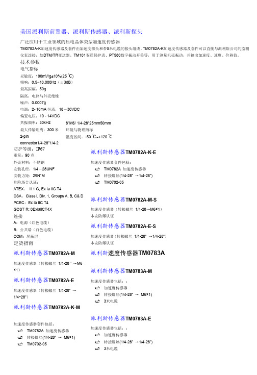
美国派利斯公司产品介绍—振动传感器系列美 国 派 利 斯 电 子 ( 北 京 ) 有 限 公 司北京朝阳区南磨房路37号华腾北搪商务大厦1905室邮编:100022电话:(010)5190-8800 传真:(010)5190-8761邮件: china@ 网址:1地震式探头选型指南美国派利斯公司产品介绍—振动传感器系列美 国 派 利 斯 电 子 ( 北 京 ) 有 限 公 司加速度传感器 TM0782A广泛应用于工业领域的压电晶体类型加速度传感器TM0782A-K 加速度传感器及套件由加速度探头和带5米电缆的接头组成。
TM0782A-K 加速度传感器及套件可以直接与派利斯公司的监测仪表连接,如DTM/TR 变送器、TM101变送保护表、PT580数字振动开关等,用于测量机壳振动,并输出加速度、速度、位移值。
技术参数电气指标灵敏度:100mV /g ±10%(25 oC ) 频响:0.5~10,000Hz (±3dB ) 最高振幅:50g 隔离:电路与外壳绝缘 噪声:0.0007g电源:2~10mA 恒流,18-30VDC 偏置电压:10 - 14VDC 共振频率:30kHz 最大传输距离:300米环境与物理指标温度区间:-50 oC ~+120 oC防护等级:IP67重量:90克 外壳材料:不锈钢 安装孔经:1/4-28UNF 安装力矩:29N*M 危险场合认证:ATEX : II 1 G, Ex ia IIC T4CSA : Class l, Div. 1, Groups A, B, C& D ,T4 PCEC :Ex ia IIC T4 GOST R: 0ExiallCT4X连接A :电源(红色电缆)B :公共端(白色电缆) COM :屏蔽层定货指南TM0782A-M加速度传感器(转接螺丝 1/4-28”→M6×1)TM0782A-E加速度传感器(转接螺丝 1/4-28” →1/4-28”)美国派利斯公司产品介绍—振动传感器系列美 国 派 利 斯 电 子 ( 北 京 ) 有 限 公 司北京朝阳区南磨房路37号华腾北搪商务大厦1905室邮编:100022电话:(010)5190-8800 传真:(010)5190-8761邮件: china@ 网址:3TM0782A-K-M加速度传感器套件包括: 9 TM0782A 加速度传感器 9转接螺丝(1/4-28” → M6×1) 9 TM0702-05TM0782A-K-E加速度传感器套件包括: 9 TM0782A 加速度传感器 9转接螺丝(1/4-28” →1/4-28”) 9 TM0702-05TM0782A-M-S9 加速度传感器(转接螺丝 1/4-28→M6×1) 9 本安防爆认证TM0782A-E-S9 加速度传感器(转接螺丝 1/4-28” →1/4-28”) 9 本安防爆认证TM0782A-K-M-S加速度传感器套件包括: 9 TM0782A 加速度传感器 9 转接螺丝(1/4-28″→M6×1)9TM0702-059 本安防爆认证 TM0782A-K-E-S加速度传感器套件包括: 9 TM0782A 加速度传感器9 转接螺丝(1/4-28″→1/4-28″)9TM0702-059 本安防爆认证.附件:(标准电缆长为 5 米, XX = 05) 建议选用 TM0702-XXTM0702-XX : MIL 铝插头, 带 XX 米电缆,直径7mm 。
< 120o C (250o F)TM0703-XX : 密封型插头,带 XX 米电缆, 直径7mm 。
< 120o C (250oF)TM0704-XX : MIL 不锈钢插头, 带 XX 米铠装电缆, 直径7mm 。
< 150o C (300oF)TM0705-XX : 横向MIL 插头, 带 XX 米电缆,直径7mm 。
< 150o C (300o F)TM0710: 转接螺丝 1/4-28” → M6×1 TM0711: 转接螺丝 1/4-28” → 1/4-28” TM0712: 转接螺丝 1/4-28” → M8 TM0713: 转接螺丝 1/4-28” → M10美国派利斯公司产品介绍—振动传感器系列美 国 派 利 斯 电 子 ( 北 京 ) 有 限 公 司一体化加速度传感器TM0783A广泛应用于工业领域的压电晶体类型加速度传感器TM0783A 加速度传感器及套件由加速度探头和带3米电缆的接头组成。
TM0783A 加速度传感器及套件可以直接与派利斯公司的监测仪表连接,如DTM/TR 变送器、TM101变送保护表、PT580数字振动开关等,用于测量机壳振动,并输出加速度、速度、位移值。
技术参数电气指标灵敏度:100mV /g ±10%(25 oC ) 频响:0.5~10,000Hz (±3dB ) 最高振幅:50g 隔离:电路与外壳绝缘 噪声:0.0007g电源:2~10mA 恒流,18~30VDC 偏值电压:10~14VDC 共振频率:30kHz 最大传输距离:300米环境与物理指标温度区间:-50 oC ~+120 oC防护等级:IP67重量:90克 外壳材料:不锈钢 安装孔经:1/4-28UNF 安装力矩:29N*M连接A :电源(红色电缆)B :公共端(白色电缆) COM :屏蔽层定货指南TM0783A-M加速度传感器包括:: 9 加速度传感器9转接螺丝(1/4-28” → M6×1) 9 3米电缆TM0783A-E加速度传感器包括:: 9 加速度传感器9 转接螺丝(1/4-28” →1/4-28”) 93米电缆附件TM0710: 转接螺丝 1/4-28” → M6×1 TM0711: 转接螺丝 1/4-28” →1/4-28” TM0712: 转接螺丝 1/4-28” →M8 TM0713: 转接螺丝 1/4-28” →M10美国派利斯公司产品介绍—振动传感器系列美 国 派 利 斯 电 子 ( 北 京 ) 有 限 公 司北京朝阳区南磨房路37号华腾北搪商务大厦1905室邮编:100022电话:(010)5190-8800 传真:(010)5190-8761邮件: china@ 网址:5速度传感器 TM0793V压电晶体类型速度传感器TM0793V-K 加速度传感器及套件包括加速度探头和一根5米长的电缆。
TM0793V-K 可以直接与派利斯公司的监测仪表连接,如DTM 数字变送表、TR 变送器、TM101变送保护表、PT580数字振动开关等。
用于测量机壳振动,并输出速度或位移信号。
技术参数电气指标灵敏度:4.0mV/mm/sec ±10%,@ 25oC 振幅:5.0V pk 线性度:1%频响:1.5~7,000Hz (±3dB) 隔离:电路与外壳绝缘 横向灵敏度:< 5%电源:3~10mA 恒流,18~30VDC 偏值电压:10~14VDC 共振频率:15 kHz最大传输距离:300 米 (1,000 feet)环境和物理指标温度区间:-50 oC ~+120 oC防护等级:IP67重量:250克 外壳材料:不锈钢 安装孔经:1/4-28UNF 安装力矩:29N*M危险场合认证:ATEX: II 1 G, Ex ia IIC T4CSA:Class I, Div. 1, Groups A,B,C,D @ T4 PCEC: Ex ia IIC T4 GOST R: 0 Ex ia IIC T4X连接A :电源(红色电缆)B :公共端(白色电缆) COM :屏蔽层定货指南TM0793V-K-M速度传感器套件包括:: 9 TM0793V 速度传感器 9转接螺丝(1/4-28” → M6×1) 9 T M0702-05TM0793V-K-E加速度传感器套件包括:: 9 TM0793V 速度传感器 9转接螺丝(1/4-28” →1/4-28”) 9 TM0702-05TM0793V-M速度传感器(转接螺丝 1/4-28” →M6×1)TM0793V-E速度传感器(转接螺丝 1/4-28” →1/4-28”)美国派利斯公司产品介绍—振动传感器系列美 国 派 利 斯 电 子 ( 北 京 ) 有 限 公 司北京朝阳区南磨房路37号华腾北搪商务大厦1905室邮编:100022电话:(010)5190-8800 传真:(010)5190-8761邮件: china@ 网址:TM0793V-K-M-S速度传感器套件包括:9 TM0793V速度传感器 9 转接螺丝(1/4-28″→M6×1) 9 TM0702-05 9 本安防爆认证TM0793V-K-E-S加速度传感器套件包括: 9 TM0793V速度传感器 9 转接螺丝(1/4-28″→1/4-28″) 9 TM0702-05 9 本安防爆认证TM0793V-M-S9 速度传感器(转接螺丝 1/4-28” →M6×1) 9 本安防爆认证TM0793V-E-S9 速度传感器(转接螺丝 1/4-28” →1/4-28”) 9 本安防爆认证附件:(标准电缆长为 5 米, XX = 05) 建议选用 TM0702-XXTM0702-XX : MIL 铝插头, 带 XX 米电缆,直径7mm 。
< 120o C (250o F)TM0703-XX : 密封型插头,带 XX 米电缆, 直径7mm 。
< 120o C (250oF)TM0704-XX : MIL 不锈钢插头, 带 XX 米铠装电缆, 直径7mm 。
< 150o C (300oF)TM0705-XX : 横向MIL 插头, 带 XX 米电缆,直径7mm 。
< 150o C (300o F)TM0710: 转接螺丝 1/4-28” → M6×1 TM0711: 转接螺丝1/4-28” →1/4-28” TM0712: 转接螺丝1/4-28” →M8 TM0713: 转接螺丝1/4-28” → M10美国派利斯公司产品介绍—振动传感器系列美 国 派 利 斯 电 子 ( 北 京 ) 有 限 公 司北京朝阳区南磨房路37号华腾北搪商务大厦1905室邮编:100022电话:(010)5190-8800 传真:(010)5190-8761邮件: china@ 网址:7低频速度/位移传感器 TM079VDTM079VD 传感器是专门为采集低频振动信号所设计的传感器 ,输出速度和位移信号。
9 低频测量最低达到 30 rpm 的速度和位移信号 9 不锈钢外壳封装9 非常适用于低频机械 (水轮机, 冷却塔, 风扇和风力发电机)9 大信号输出,高信噪比9传感器分为水平安装或者垂直安装技术指标电气指标灵敏度: 速度:40 mV/mm/s (1000mV/in/sec), pk, @ 25oC, ±10% 位移:4.0mV/µm (100mV/mil), pk–pk, @ 25o C, ±10% 最高振幅:速度:100mm/s pk 位移:2000µm pk-pk 频响:0.5~20Hz (±3dB ) 隔离:电路与外壳绝缘.电源:3 - 10mA 恒流源 18 - 30VDC 输出阻抗:50欧.输出偏置电压:10~14VDC最大传输距离:300 米 (1,000英尺) 环境与物理指标温度区间:-20 o C ~+70 o C 防护等级:IP67 重量:1400g外壳材料:304不锈钢. 固定螺丝:3/4 NPT 或M20 安装力矩:29N*M输出接口:A :电源 (红)B :COM (白)定货指南TM079VD-V-K-AXX-BXX垂直安装低频速度传感器TM079VD-H-K-AXX-BXX水平安装低频速度传感器 AXX : 灵敏度A00: 速度: 40 mV/mm/s (1000mV/in/sec), pk A01: 位移: 4.0mV/µm (100mV/mil), pk–pk BXX : 安装 B00:3/4” NPTB01:M20 B02:M20×1.5附件TM0716:安装螺纹 M20×1.5 TM0717:安装螺纹 3/4” NPT TM0718:安装螺纹 M20TM0702-XX :同TM0782A 接头附件(建议选用) TM0703-XX :同TM0782A 接头附件 TM0704-XX :同TM0782A 接头附件 TM0705-XX :同TM0782A 接头附件。