钻头选型外文文献
Part II--钻头选型解析

9.钻头期望值
➢ 钻头使用目的; ➢ 机械钻速; ➢ 钻头进尺.
10.经济评价
Cb + Cr (Tb + Tc + Tt) Cf=
H ➢ Cf-----每米钻井成本; ➢ Cb----钻头价格; ➢ Cr----钻机日作业费; ➢ Tb----纯钻进时间; ➢ Tc----辅助时间; ➢ Tt-----起下钻时间; ➢ H------钻头进尺.
200
400
600
800
TRQ (kn.m )--S91JT5737 0 5 10 15 20
200
400
600
800
FR (l/min)--S91JT5737 320 340 360 380 400 00000 200
400
600
800
1000
1000
1000
1200
1200
1200
1400
1400
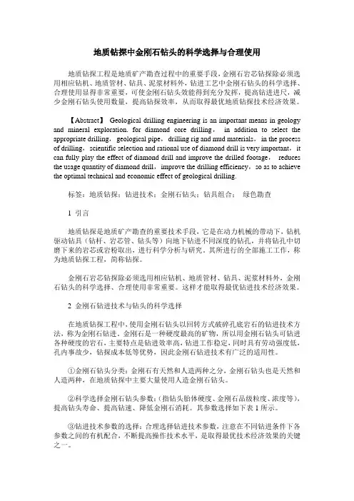
泥 面:35.00m
20"隔水导管入泥45m 9-5/8"套管前置浆返至13-3/8"套 管 鞋 上 下 至 少 各 100m 17-1/2"井眼:205.00m 13-3/8"套管:200.00m
水泥返高1100m
12-1/4"井眼@1752米 9-5/8"套管@1750米
8-1/2"井眼1750-2205米 8-1/2"分支井眼100-150米
1. 地层岩性--地层变性
地层较深的泥岩地层,在大钻压下, 机械钻速低于1.5米/小时,如果静液 柱压力>6500 psi 时,将产生塑性, 岩屑又长又细. 即: 井眼垂深(英尺)X泥浆密度(磅/ 加仑)X0.052 >=6500 psi
地层评价用于钻头分析和选型
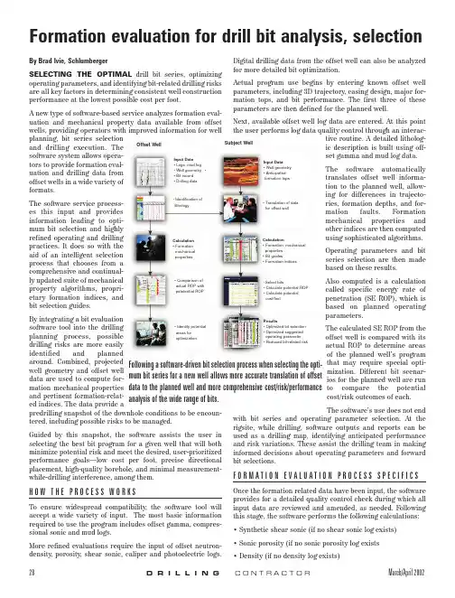
• Comparison of actual ROP with potetential ROP
• Select bits • Calculate potential ROP • Calculate potential
cost/foot
Also computed is a calculation called specific energy rate of penetration (SE ROP), which is
uation and mechanical property data available from offset Next, available offset well log data are entered. At this point
wells, providing operators with improved information for well the user performs log data quality control through an interac-
bit selection guides.
based on planned operating
Calculation • Formation
mechanical properties
Calculation • Formation mechanical
properties • Bit guides • Formation indices
using sophisticated algorithms.
The software service processes this input and provides
Input Data • Logs, mቤተ መጻሕፍቲ ባይዱd log • Well geometry • Bit record • Drilling data
刀具文献中英文对照
英文文献Design Of Tool Machine PropThe original knife machine control procedures are designed individually, not used tool management system, features a single comparison, the knife only has to find the tool knife, knife positioning the shortest path, axis tool change, but does not support large-scale tool.Automatic knife in the knife election, in the computer memory knife-election on the basis of using the Siemens 840 D features, and the election procedures knife more concise, and complete the space Daotao View. ATC use the knife rapid completion of STEP-7 programming, and have been tested in practice. In the positioning of the knife, PLC controlled modular design method, which future production of similar machines will be very beneficial, it is easy to use its other machine. Automatic tool change systems will be faster growth, reduced tool change time, increase the positioning accuracy tool is an important means to help NC technology development.Tool and inventory components of modern production is an important link in the management, especially for large workshop management. The traditional way of account management, and low efficiency, high error rate, and not sharing information and data, tools and the use of state can not track the life cycle, are unable to meet the current information management needs. With actual production, we have to establish a workshop tool for the three-dimensional tool storage system to meet the knife workshop with auxiliary storage and management needs.The system uses optimization technology, a large number of computer storage inventory information, timely, accurate, and comprehensive tool to reflect the inventory situation. The entire system uses a graphical interface, man-machine dialogue tips from the Chinese menu, select various functions can be realized and the importation of all kinds of information. Management system using online help function. Through the workshop management, network management and sharingof information. Have automated inventory management, warehousing management tool, a tool for the management and statistical functions.The entire system, including the structure and electrical machinery control systems.(1)Mechanical structure and working principleTool from the stent, drive, drive system, Turret, shielding, control system, and electrical components. Support from the column, beam, the upper and lower guide Central track, and track support component.Drive for the system chosen VVVF method. Cone used brake motors, with VVVF by Cycloid reducer through sprocket drive.Drag a variable frequency drive system and control technology. VVVF adopted, will speed drive shaft in the normal range adjustment to control the speed rotary turret to 5 ~ 30mm in, the drive shaft into two, two under through sprocket, the two profiled rollers Chain driven rotating shelves. Expansion chain adopted by the thread tight regulation swelling, swelling the regular way. - Conditioned, under the same chain-of-conditioning, so that the chain of uniform.Turret and shields the entire total of 14 independent Turret. 13 of them as a socket-Turret, as a drawer-Turret, each Turret back through the pin and, under the conveyor chain link chain plate, installed at the bottom roller, chain driven rotating turret rotation along the track. Outlet-Turret and BT50-BT40 Turret Turret two kinds of forms. To strengthen management, security, landscaping modeling, shelf peripherals and shields. Turret-drawer drawer placed at six other Des Voeux a knife, can be categorized with some of knife auxiliary equipment, such as bits, such as turning tools.(2)Electrical Control SystemThis tool storage systems is the main electrical control their shelves for operational control and position control. Operational control equipment, including operation of the start of braking control. Position Control is the main location and address of the shelves for testing.Electric Transmission horizontal rotary tool storage systems are the mechanical movements are repeated short-term work system. And the run-time system needs some speed, speed transmission needs, the system will use VVVF method can be used simple structure, reliable operation of the motor and frequency inverter.Control of the system is divided into two kinds of manual control and automatic control, manual control as a general reserve and debugging methods of work; ways to the system control computer (IPC) and the control unit (inverter contactor , etc.) consisting of a control system.location and positioning accuracy of the system automatically identify the siteand location using a detection device as proximity switches, relays through the plate-point isolation and the number plate recorded close to the switching signal acquisition and operation of Hutchison with a Optimal Path addressable identify the current location and shelves of the purpose of the shelf location. In order to enable a more accurate positioning system, adopted two photoelectric switches, to detect the two shelves of the two films.ConclusionFocused on in today's manufacturing environment tool storage and management of new models and methods, practical application of good results in systems integration and optimization, and other aspects of operations will be further explored, so that it has a higher theoretical and practical level.中文翻译:机床刀具设计机床原来的刀库控制程序是单独设计的,没有采用刀具管理系统,功能也比较单一,只实现了刀库刀具的找刀、刀库最短路径定位、主轴换刀,而且不支持大型刀具。
砂砾岩地层钻头合理选型研究及应用
文章编号 : 1000 - 7393 (2005) 03 - 0013 - 02
方法 。 ( 3 )对地层力学参数与钻头类型之间关系模型
的探讨只是初步的 ,还需要在理论上和实际应用中
(收稿日期 2005201230) 〔编辑 薛改珍 〕
82
O IL DR ILL ING & PRODUCTION TECHNOLOGY June 2005
O IL D R ILL ING & PROD UCT IO N TECHNOLO GY Vol. 27 No. 3 June 2005
3攻关项目 :中原油田 2004年重点科技攻关项目“吉林油田乾安地区可钻性综合评价及钻头优选研究 (编号 zyytze2004 - 03 - 022) ”。
作者简介 :纪明师 , 1958年生 。1998年毕业于河南财经学院工程管理专业 ,现为吉林项目部经理 ,高级工程师 。电话 : 0393 - 4826163。
4 结论
(1)对于难钻的砂砾岩地层 ,通过测井资料处 理分析进行钻头选型 ,能够得到一个合理的结果 。
(2)实践证明 ,利用测井资料和实钻的钻头资 料相结合进行钻头选型是一种切实可行的钻头选型
作进一步的研究 ,这样才能保证钻头选型的合理性 。
参 考 文 献
[ 1 ] 田军 ,陈德光. 利用测井资料预测地层岩石可钻性. 石 油钻采工艺 , 1994, 16 (3) : 24~27
14
石油钻采工艺 2005年 6月 (第 27卷 )第 3期
钻头如何打造的英文作文
钻头如何打造的英文作文Title: The Art of Crafting Drill Bits。
Crafting drill bits is a fascinating process that merges precision engineering with metallurgical expertise. These seemingly simple tools undergo a complex manufacturing journey before they find their place in various industries. In this essay, we delve into the intricate process of creating drill bits, exploring the meticulous steps involved in their production.The journey of crafting a drill bit begins with the selection of raw materials. High-quality steel, tungsten carbide, and cobalt alloys are commonly used due to their durability and ability to withstand high temperatures and pressures. These materials are meticulously inspected for impurities before being shaped into cylindrical rods through processes like extrusion or casting.Once the raw materials are prepared, the next stepinvolves heat treatment to enhance their mechanical properties. This process typically includes annealing, quenching, and tempering, which alter the internalstructure of the material to improve its strength and hardness. The precise control of temperature and cooling rates during heat treatment is crucial to achieving the desired properties in the final product.After heat treatment, the rods are machined into the desired shape using computer numerical control (CNC) machines or other advanced manufacturing techniques. This stage requires exceptional precision to ensure that each drill bit meets the exact specifications required for its intended application. The cutting edges are ground torazor-sharp precision, and special coatings may be applied to enhance wear resistance and lubricity.Quality control is a critical aspect of the manufacturing process to ensure that every drill bit meets rigorous standards. Advanced inspection techniques, such as optical and laser scanning, are employed to detect even the slightest deviations from the desired dimensions andtolerances. Any defective drill bits are promptlyidentified and either reworked or discarded to maintain the highest level of quality.Once the manufacturing process is complete, thefinished drill bits undergo rigorous testing to validate their performance characteristics. This includes testingfor hardness, torsional strength, and cutting efficiency under simulated operating conditions. Only drill bits that meet or exceed performance criteria are deemed suitable for commercial distribution.The final stage of the process involves packaging and distribution to end-users across various industries, including construction, manufacturing, and mining. Eachdrill bit is carefully packaged to prevent damage during transit and storage, ensuring that it arrives in pristine condition ready for use.In conclusion, the creation of drill bits is a precise and intricate process that requires a blend of engineering expertise, metallurgical knowledge, and advancedmanufacturing techniques. From the selection of raw materials to the final testing and distribution, every step is meticulously executed to produce drill bits of the highest quality and performance. These seemingly simple tools play a vital role in countless industries, driving progress and innovation through their reliability and efficiency.。
地质钻探中金刚石钻头的科学选择与合理使用
地质钻探中金刚石钻头的科学选择与合理使用地质钻探工程是地质矿产勘查过程中的重要手段,金刚石岩芯钻探除必须选用相应钻机、地质管材、钻具、泥浆材料外,钻进工艺中金刚石钻头的科学选择、合理使用显得非常重要,可使金刚石钻头效能得到充分发挥,提高钻进进尺,减少金刚石钻头使用数量,提高钻探效率,从而取得最优地质钻探技术经济效果。
【Abstract】Geological drilling engineering is an important means in geology and mineral exploration. for diamond core drilling,in addition to select the appropriate drilling,geological pipe,drilling rig and mud materials,in the process of drilling,scientific selection and rational use of diamond drill is very important,it can fully play the effect of diamond drill and improve the drilled footage,reduces the usage quantity of diamond drill,improve the drilling efficiency,so as to achieve the optimal technical and economic effect of geological drilling.标签:地质钻探;钻进技术;金刚石钻头;钻具组合;绿色勘查1 引言地质钻探是地质矿产勘查的重要技术手段,它是在动力机械的带动下,钻机驱动钻具(钻杆、岩芯管、钻头等)向地下钻进不同深度的钻孔,并将钻孔中切磨下来的岩芯或岩粉取出,进行科学分析与研究。
机械加工钻床中英文对照外文翻译文献
中英文对照外文翻译文献(文档含英文原文和中文翻译)原文:Drilling and Milling MachinesUpright drilling machines or drill presses are available in a variety of sizes and types, and are equipped with a sufficient range of apindle speeds and automatic feeds to fit the neds of most industries. Speed ranges on a typical machine are from 76 to 2025 rpm., with drill feed from 0.002 to 0.020 in.per revolution of the spindle.Radial drilling machines are used to drill workpieces that are too largeor cumbersome to conveniently move. The spindle with the speed and feed changing mechanism is mounted on the radial arm; by combining the movement of the radial arm around column and the movement of the spindle assembly along the arm, it is possible to align the spindle and the drill to any position within reach of the machine. For work that is too large to conveniently support on the base, the spindle assembly can be swung out over the floor and the workpiece set on the beside the machine.Plain radial drilling machines provide only for vertical movement of the spindle; universal machines allow the spindle to swivel about an axis normal to the radial arm and the radial arm to rotate about a horizontal axis, thus permitting drilling at any angle.A multispindle drilling machine has one or more heads that drive the spindles through universal joints and telescoping splined shafts. All spindles are usually driven by the same motor and fed simultaneously to drill the desired number of holes. In most machines each spindle is held in an adjustable plate so that it can be moved relative to the others. The area covered by adjacent spindles overlap so that the machine can be set to drill holes at any location within its range.The milling operation involves metal removal with a rotating cutter. It includes removal of metal from the surface of a workspiece, enlarging holes, and form cutting, such as threads and gear teeth.Within an knee and column type of milling machine the column is themain supporting member for the other components, and includes the base containing the drive motor, the spindle, and the cutters. The cutter is mounted on an arbor held in the spindle, and supported on its outer extremity by a bearing in the overarm. The knee is held on the column in dovetail slots, the saddle is fastened to the knee in dovetail slots, and the table is attached to the saddle. Thus, the build-up the knee and column machine provides three motions relative to the cutter. A four motion may be provided by swiveling the table around a vertical axis provided on the saddle.Fixed-bed milling machines are designed to provide more rigidity than the knee and column type. The table is mounted directly on the machine base, which provides the rigidity necessary for absorbing heavy cutting load, and allows only longitudinal motion to the table. Vertical motion is obtained by moving the entire cutting head.Tracer milling is characterized by coordinated or synchronized movements of either the paths of the cutter and tracing elements, or the paths of the workpiece and model. In a typical tracer mill the tracing finger follow the shape of the master pattern, and the cutter heads duplicate the tracer motion.The following are general design considerations for milling:1. Wherever possible, the part should be designed so that a maximum number of surfaces can be milled from one setting.2. Design for the use of multiple cutters to mill several surfaces simultaneously.3. The largest flat surface will be milled first, so that all dimensions are best referred to such surface.4. Square inside corners are not possible, since the cutter rotates.Grinding Machines and Special Metal-removal ProcessRandom point-cutting tools include abrasives in the shape of a wheel, bonded to a belt, a stick, or simply suspended in liquid. The grinding process is of extreme importance in production work for several reasons.1.It is most common method for cutting hardened tool steel or other heat-treated steel. Parts are first machined in the un-heat-treated condition, and then ground to the desired dimensions and surface finish.2.It can provide surface finish to 0.5µm without extreme cost.3.The grinding operation can assure accurate dimensions in a relatively short time, since machines are built to provide motions in increments of ten-thousandths of an inch, instead of thousandths as is common in other machines.4.Extremely small and thin parts can be finished by this method, since light pressure is used and the tendency for the part to deflect away from the cutter is minimized.On a cylindrical grinding machine the grinding wheel rotates between 5500 and 6500 rpm., while the work rotates between 60 and 125 rpm... The depth of cut is controlled by moving the wheel head, which includes both the wheel and its drive motor. Coolants are provided to reduce heat distortion and to remove chips and abrasive dust.Material removal from ductile materials can be accomplished by using a tool which is harder than the workpiece. However during Word War Ⅱ the widespread use of materials which were as hard or harder than cutting tools created a demand for new material-removal methods. Since then a number of processes have been developed which, although relatively slow and costly, can effectively remove excess material in a precise and repeatable fashion. There are two types of processes. The first type is based on electrical phenomena and is used primarily for hard materials; the second depends upon chemical dissolution.Chemical milling is controlled etching process using strong alkaline or acid etchants. Aluminum, titanium, magnesium, and steel are the principal metals processed by this method. The area to remain untouched by the etchant are masked with a protective coating. For example, the entire part may be dipped in the masking material and the mask removed from those areas to be etched, or a chemically resistant prescribed time, after which the part is rinsed in cold water, the masking removed, the part inspected, and thoroughly cleaned.There are certain disadvantages to consider. Metal will erode equally in all directions, so that walls of the etched section will have a radius equal to the depth of etch. A second disadvantage is that a better finish is obtained on surfaces parallel to the direction of rolling of a sheet than on surface perpendicular to the direction of rolling. This can be compared to the surface obtained when working wood parallel to, or across the grain.A third disadvantage, not unique with this process, is the warpage that will occur in thin, previously stressed sections etched on just one side.Chemical milling, however, has many advantages over conventional metal-removal methods. There is no warpage of heavy sections such as forgings or extrusions when the etchant is applied simultaneously to all sides for reduction of section thickness. In conventional milling only one side can be worked at a time, and frequent turning of a part is necessary to prevent warpage. Chemical milling can be applied to parts of irregular shape where conventional milling may be very difficult. Light-weight construction can be obtained with chemical milling by the elimination of welding, riveting, and stiffeners; parts can be contoured to distribute the load in the most suitable manner. As an example of the potential savings of this process, as compared to machine milling, one company reports that the cost of removing aluminum by chem.-milling is $0.27 per pound as compared to $1.00 per pound by conventional milling. The rate of metal removal for chem.-milling is 0.001in. for aluminum.Electric-discharge machining is a process in which an electrical potential is impressed between the workpiece and the tool, and the current, emanating from a point source on the workpoiece, flows to the tool in the form of a spark. The forces that accomplish the metal removal are within the workpiece proper and, as a result, it is not necessary to construct the unit to withstand the heavy pressures and loads prevalent with conventional machining methods.The frequency of the electrical discharge ranges from 20,00 cps (cycles per second) for rough machining, to 50,000 cps for finishing such items as hardened tools and dies. The current may vary from 50 amp, during rough machining, to as low as 0.5 amp, during finishing. The process is currently applied to the machining of single-point tools, form tools, milling cutters, broaches, and die cavities. It is also applicable to the removal of broken drills, taps, and studs without damaging the workpiece in which the broken tool is imbedded. Other uses are the machining of oil holes in a hardened part, and the machining of small safety-wire holes in the heads of special alloy bolts, such as titanium.The ultrasonic machining process is applied to both conducting and non-conducting material, and relies entirely upon abrasive action for metal removal. The workpiece is submerged in slurry of finely fivided abrasive particles in a vehicle such as water. The tool is coupled to an oscillator and vibrates at frequencies between 15,000 and 30,000 cps. Thevibrating tool cavitates the liquid, and the force drives the abrasive into the surface of the workpiece to remove metal chips which are carried away by the liquid. The acceleration given the abrasive grains is as much as 100,000 times the acceleration of gravity, providing a smooth and rapid cutting force.Introduction of MachiningMachining as a shape-producing method is the most universally used and the most important of all manufacturing processes. Machining is a shape-producing process in which a power-driven device causes material to be removed in chip form. Most machining is done with equipment that supports both the work piece and cutting tool although in some cases portable equipment is used with unsupported workpiece.Low setup cost for small quantities. Machining has tow applications in manufacturing. For casting, forging, and pressworking, each specific shape to be p5roduced, even one part, nearly always has a high tooling cost. The shapes that may be produced, even one part, nearly always has a high tooling cost. The shapes that may be produced by welding depend to a large degree on the shapes of raw material that are available. By making use of generally high cost equipment but without special tooling, it is possible, bu machining, to start with nearly any form of any material, so long as the exterior dimensions are great enough, and produce any desiredshape from any material. Therefore, machining is usually the preferred method for producing one or a few parts, even when the design of the part would logically lead to casting, forging or pressworking if a high quantity were to be produced.Close accuracies, good finishes. The second application for machining is based on the high accuracies and surface finishes possible. Many of the parts machined in low quantities would be produced with lower but acceptable tolerances if produced in high quantities by some other process. On the other hand, many pars are given shapes by some high quantity deformation process and machined only on selected surfaces where high accuracies are needed. Internal threads, for example, are seldom produced by any means other than machining and small holes in pressworked parts may be machined following the pressworking operations.钻床和铣削直式钻床或钻孔式印刷机可用于各种尺寸和种类,它能安装轴速度的足够范围和自动运转以适应大多工业的要求。
【机械类文献翻译】多功能工具钻参数的优化选择
英文原文原文节选自Journal of Materials Processing Technology 103 (2000) 318-323 《Optimal selection of parameters in multi-tool drilling》原文:Optimal selection of parameters in multi-tool drillinga.Department of Mechanical Engineering, Indian Institute of Technology, Chennai 600 036, Indiab.Department of Humanities and Social Sciences, Indian Institute of Technology, Chennai 600 036,IndiaAccepted 4 January 2000AbstractIn hole-making operation, the final size may be obtained by drilling with a single drill orpilot-drilling of one or more holes followed by enlargement to the final size. In this paper, a model based on production cost is presented and the optimal conditions are obtained considering technological and machine tool constraints. This approach is quite useful in arriving at the cutting parameters automatically in a computer-assisted process planning system.Keywords: Optimal selection; Multi-tool drilling; Computer-assisted process planning systemNomenclatureD drill diameter, mmd pilot-drill diameter, mmF thrust force in drilling, Nh1 tool return rate, min/mmh2 time for tool retract-advance, mink1 operating cost of drilling machine, $/minkt drill cost, $l depth of drilling, mmM torque in drilling, N ms feed, mm/revT drill-life, minTR preventive tool-lifet depth of cut, 错误!未找到引用源。
钻孔机机械外文文献翻译、中英文翻译、外文翻译
附录Ⅱ钻孔机是指利用比目标物更坚硬、更锐利的工具通过旋转切削或旋转挤压的方式,在目标物上留下圆柱形孔或洞的机械和设备统称。
也有称为钻机、打孔机、打眼机、通孔机等。
通过对精密部件进行钻孔,来达到预期的效果,钻孔机有半自动钻孔机和全自动钻孔机,随着人力资源成本的增加;大多数企业均考虑全自动钻孔机作为发展方向。
随着时代的发展,自动钻孔机的钻孔技术的提升,采用全自动钻孔机对各种五金模具表带钻孔表带钻孔首饰进行钻孔优势明显。
中国是全世界生产和输出的最大国家,占全球制表行业90%以上,全自动高速表带钻孔机彻底解决表带行业目前投入人力最多,产出最少的手工钻孔工艺现状的困难,全面取代现有的手工钻孔工艺,也间接解决了企业招收熟练钻孔工人困难的严重问题。
同时为企业节约了大量的人力成本开支。
钻孔机是指利用比目标物更坚硬、更锐利的工具通过旋转切削或旋转挤压的方式,在目标物上留下圆柱形孔或洞的机械和设备统称。
也有称为钻机、打孔机、打眼机、通孔机等。
通过对精密部件进行钻孔,来达到预期的效果,钻孔机有半自动钻孔机和全自动钻孔机,随着人力资源成本的增加;大多数企业均考虑全自动钻孔机作为发展方向。
随着时代的发展,自动钻孔机的钻孔技术的提升,采用全自动钻孔机对各种五金模具表带钻孔表带钻孔首饰进行钻孔优势明显。
手动钻孔机,包括一个手动传递机构,一个轴向进给机构,一个导向机构,一个间隙调整机构,手动传递机构由主轴、与主轴上端部相连的扳手及与主轴下端部相连的钻头、套钻构成;轴向进给机构由手轮、蜗杆、蜗轮、螺母、丝杆构成;导向机构由上端通过箱与螺母配合下端与丝杆相连接的护箱构成间隙调整机构由螺母上方的与主轴相连的调整螺母、设在螺母上端部两侧的两平面轴承构成。
产品密封性能良好,工作稳定,劳动强度低、可一机多用。
它可用作在输送液体或气体的管道上,不停止其输送工作进行带压钻孔以便安装分支管道的装置。
但是手动钻孔的弊端就是占用过多的劳动力与工作时间。
ROLLING CUTTER BITS牙轮钻头英文简介
3. Allows maximum coverage of the hole bottom.
The bottom hole coverage of most bits is about 70%.
• The outer row of bit teeth, heel teeth, has the hardest job.
– The most advanced bearing type
– The roller bearings are eliminated and the cone rotates in contact with the journal bearing pin. – By eliminating one of the rollers, additional space becomes available for strengthening the remaining components. – Has the advantage of greatly increasing the contact area through which the WOB transmitted on the cone.
– The grease seals require some space and, thus, a reduction in bearing capacity. – The elimination of abrasive material from bearings usually more than compensates for this disadvantage.
• Offset angle: