美国主办第一届激光冲击强化会议PPT(8)_报告者:NASA Johnson 空间中心
《激光的基本原理》课件

利用光子学技术,可以实现高灵敏度、高分辨率的医学成 像和诊断。同时,光子学技术还可以用于生物科学研究, 如荧光共振能量转移等技术可以用于研究生物分子间的相 互作用和动力学过程。此外,光子学技术还可以用于光热 治疗、光动力治疗等领域,为癌症治疗等提供新的手段。
THANKS
感谢观看
详细描述
超快激光技术可以用于超快光谱学、 超快成像等领域,为物质科学研究提 供新的工具。同时,超快激光技术还 可以用于微纳加工、光刻等领域,提 高加工精度和效率。
光子晶体激光器的研究与应用
总结词
光子晶体激光器是一种新型的激光器件,具 有高效率、高稳定性等优点,在光通信、光 计算等领域具有广阔的应用前景。
随着技术的进步和应用需求的不断增长,激光技术逐渐拓展 到工业、医疗、通信、军事等领域,成为现代科技的重要组 成部分。
激光的重要性和应用领域
激光具有高亮度、高方向性、高单色 性和高相干性等优点,因此在科学研 究、工业生产、医疗卫生、军事等领 域有广泛的应用。
此外,激光还在通信、测量、军事等 领域中发挥着重要的作用,有力地推 动了科学技术的发展和社会进步。
1960年,美国物理学家梅曼发明了第一台红宝石激光器,标志着激光技 术的诞生。
激光的英文名称是“Laser”,是“Light Amplification by Stimulated Emission of Radiation”的缩写,意为“受激发射光放大”。
激光的发展历程
激光技术经历了从初步实现到逐步成熟的发展过程,各种不 同类型的激光器也不断涌现,如气体激光器、固体激光器、 液体激光器和半导体激光器等。
例如,在工业领域中,激光可以用于 打标、切割、焊接、热处理等;在医 疗领域中,激光可以用于治疗眼科疾 病、皮肤病、口腔疾病等。
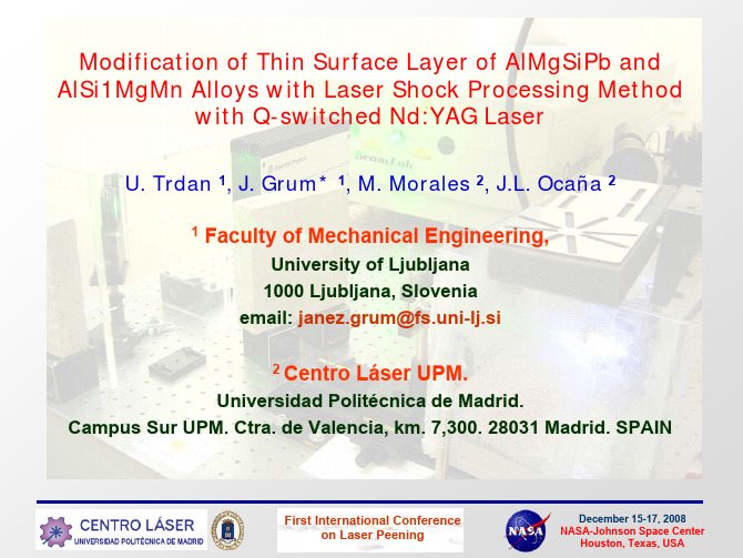
美国主办第一届激光冲击强化会议PPT(10)_报告者:西班牙Ljubljana大学

December 15-17, 2008 NASA-Johnson Space Center Houston, Texas, USA
Experimental results
Microhardness Analysis (HV0,2)
First International Conference on Laser Peening
December 15-17, 2008 NASA-Johnson Space Center Houston, Texas, USA
Experimental results
Pitting Corrosion Analysis
First International Conference on Laser Peening
December 15-17, 2008 NASA-Johnson Space Center Houston, Texas, USA
Properties of treated materials
First International Conference on Laser Peening
December 15-17, 2008 NASA-Johnson Space Center Houston, Texas, USA
December 15-17, 2008 NASA-Johnson Space Center Houston, Texas, USA
INTRODUCTION
Laser Shock Processing is an innovative surface treatment, with which a short pulse laser produces elasto-plastic shifts at the atom level, which considerably increases densification of dislocations in the thin surface layer, which reflects mainly in modified mechanical properties. LSP produces shocks of motive quantity, which produce considerable densification of dislocations and generation of compressive residual stresses of high gradient (Grum et al., 2008). In practice, technologists and engineers frequently require the introduction of compressive residual stresses since the latter improves fatigue resistance of a material (Hammersley et al., 2000, Ocaa et al., 2004). LSP is frequently applied to exacting components, particularly in the aircraft industry for treatment of the most demanding components such as turbine spades of an aircraft F-16 Falcon and a bombardier F-22 Rockwell. In numerous studies Sano et al. (2002) confirmed the applicability of LSP, particularly because of improved material resistance to stress-corrosion cracking (SCC). Corrosion tests carried out in a vapour chamber for 500 hours confirmed an influence of LSP on increased material resistance to SCC. The same specimens were also used to perform a microscopic analysis, which confirmed the presence of cracks in the specimens in the as-delivered state whereas in the LSP-treated specimens no cracks were found. It has been found that a correct choice of the processing parameters provided desired variations of hardness and residual stresses in the surface of machine components can be achieved, which, in turn, provided improved material fatigue resistance.
美国主办第一届激光冲击强化会议PPT(9)_报告者:韩国...

General Properties
High strength Good resistance to pitting and crevice corrosion High resistance to stress corrosion cracking and corrosion fatigue Good resistance to uniform corrosion Good erosion resistance Good fatigue resistance High energy absorption Low thermal expansion Good weldability ()
4% ↓ 4% ↓ 1% ↓ 1% ↑ 2% ↑ 6% ↑
345
360 345 330
Hardness
Hardness
330
315 10 20
Overlapping
10
20 Overlapping
30
30
No peening (Ave.) Laser intensity 250mJ/mm2 and Cu (100 μm) coating No polishing for HV
Scan speed (v) 0.65×D (D= diameter)
Total irradiation area : 10mm × 10 mm
Laser Micro/Nano Fabrication Lab.
9/19
GIST
Micro Vickers Results
Coated (Cu) sample vs. Non-coated sample Laser fluence (200, 250, 300 mJ/mm2)
美国主办第一届激光冲击强化会议PPT(1)_报告者:普惠公司

7
Gas Turbine HCF Environment is Complex
Requires OEM Hardware and System Experience
12000
Operational environment iin airfoil vibratory stress response – absolute and blade-to-blade Structural dynamics are complex with many resonant modes and drivers in operational speed range
10000
Idle 40K SLTO
40E (S6)
8000
Frequency(Hz) Frequency (Hz)
6000
1 CWB
Redline
20E
4000
2000
M4 M3 M2
10E Struts
6E M1
– Or . . .
0 7500
8500
9500
10500
11500
12500
N2 RPM
Presentation Outline
Background & Motivation Challenges The Way Forward – Critical Steps Summary
This shipment contains no technical data as defined by 22 CFR 120.10(5) Public Release Approval Pending
– Requires comprehensive, integrated analytical capability to minimize
激光冲击强化技术

激光冲击强化技术摘要:本文主要从作用机理、强化机理及影响因素等方面系统的介绍了激光表面强化技术。
关键词:激光表面强化、冲击波、晶粒细化Laser Shock Processing TechnologyAbstract: This article mainly introduces Laser shock processing (LSP) from the respect of the interaction mechanism, the strengthening mechanism and the influencing factors.Keyword:LSP ,shock wave, grain refinement1 引言激光冲击强化技术((Laser shock processing,简称LSP)作为一种新兴的表面改性处理技术起始于上世纪六十年代,也是当代具有重要意义的自然科学发明之一。
在激光表面处理技术应用之初,科学家们意外发现激光脉冲可以产生肉眼无法察觉的冲击波,如果冲击波能够连续作用于金属表面,会在金属表层形成压应力,这种压应力远大于材料本身的屈服强度,能够在金属表面形成一定深度的高幅值残余压应力层,使表层材料得到硬化,晶粒细化,通过这种方式可以实现对材料的性能的强化处理[1]。
激光表面处理技术在发展过程中出现了多种形式的处理方法,包括主要激光相变硬化(Laser Hardening)、激光熔覆(Laser Cladding)、激光表面合金化(Laser Alloying)、激光冲击强化处理(Laser Shock Processing,LSP)、激光冲击成形技术(Laser Shock Forming,LSF)等[1]。
作为一项相较于传统工艺,清洁高效的高新技术,目前激光表面处已经广泛应用于军工国防、航空航天等领域,例如微精密设备的小孔强化,损伤叶轮修复以及水下设备的抗腐蚀性强化和焊缝延寿等。
激光安全及措施ppt课件

THANKS
感谢观看
在激光器输出端应设置光束终止 装置,以确保在意外情况下及时 切断激光束,减少人员伤害风险
。
激光操作安全防护措施
操作培训
个人防护装备
安全距离
紧急停机装置
操作人员应接受专业的激光安 全培训,了解激光器的特性、 潜在风险及安全操作规程。培 训内容包括但不限于激光器的 启动、关闭、调整等操作。
操作人员在接触激光器时,应 佩戴适当的个人防护装备,如 激光防护眼镜、防护服等,以 减少对眼睛和皮肤的潜在伤害 。
激光安全管理制度和标准
01
02
03
制度目标
制定激光安全管理制度, 确保激光设备的安全使用 ,防止激光对人员和环境 造成危害。
制度内容
明确激光设备的分类、标 识、使用、维护、检查等 方面的管理要求,规范激 光安全行为。
标准遵循
遵循国家相关激光安全标 准和行业标准,确保激光 安全管理制度的科学性和 有效性。
02
激光安全防护措施
激光器的安全设计
安全外壳
激光器应配备安全外壳,以防止 人员接触到激光束和激光器内部 部件。外壳应符合国际安全标准
,并配备适当的警示标识。
控制系统
激光器的控制系统应具备安全性 设计,包括防止误操作、防止未 经授权访问等措施。电子控制部 分应具备过流、过压、过热保护
功能。
光束终止装置
在操作激光器时,应确保人员 与激光器保持安全距离,避免 直接暴露在激光束中。同时, 应在激光器周围设置明显的安 全警示区域。
激光器应配备紧急停机装置, 以便在发生异常情况时迅速切 断激光输出,确保人员安全。 紧急停机装置应设置在易于触 及的位置,并定期检查其有效 性。
03
《激光基本性质》课件
方向性
激光的光束很窄,且发散 角很小,因此具有很好的 方向性。
高亮度和相干性
激光的能量高度集中,亮 度极高。同时,由于光的 相干性,激光具有很好的 干涉和衍射特性。
激光的类型与分类
按照工作物质分类
根据产生激光的工作物质的不同 ,可以将激光分为气体激光器、 固体激光器、液体激光器和半导
体激光器等。
按照输出功率分类
近年来,随着光纤技术的不断发展, 光纤激光器成为激光技术的重要发展 方向之一,具有高亮度、高效率、低 成本等优点。
随着技术的不断进步,激光波长范围 不断扩展,从可见光到远红外、紫外 等波段,应用领域也日益广泛。
激光的重要性和应用领域
激光具有高亮度、高方向性、高单色性 等特点,因此在科学研究、工业生产、 医疗卫生、军事等领域得到广泛应用。
在军事方面,激光可以用于激光武器、 激光雷达、激光制导等领域,提高武器 装备的精度和战斗力。
在医疗卫生方面,激光可以用于眼科、 皮肤科、口腔科等领域,具有无创、无 痛、无副作用等优点。
在科学研究方面,激光可以用于光谱学 、光学物理、量子物理等领域的研究, 推动科学技术的进步。
在工业生产方面,激精度。
激光产生的条件
要产生激光,需要满足三个基本条件:工作物质、泵浦源和光学共振腔。工作物质是产生激光的物质,泵浦源用 于激发工作物质,使其达到粒子数反转分布状态,光学共振腔则用于选频和反馈,使特定频率的光得到放大。
激光的特性
01
02
03
单色性
由于激光的频率单一,因 此其光谱宽度极窄,具有 极好的单色性。
光纤激光技术
总结词
光纤激光技术是一种利用光纤作为增益介质的激光技术。
详细描述
光纤激光技术具有高效率、高稳定性和长寿命等优点,因此在通信、传感、军 事等领域有广泛应用。随着光纤激光技术的不断发展,其输出功率和光束质量 也在不断提高,有望在更高性能的领域得到应用。
美国主办第一届激光冲击强化会议PPT(12)_报告者:美国阿拉巴马大学
Normalized Radial Position (microns)
Radius approx. 20 microns Optimal peening time of 30 ns
THE UNIVERSITY OF ALABAMA
23
Dent Size at Constant Pulse Time
Pulse time = 30 ns
Peak pressure = 4 GPa
THE UNIVERSITY OF ALABAMA
16
LSP Simulations
Subroutine VDLOAD applied non-uniform shock pressure Function of TIME and POSITION Laser Spot Gaussian distribution R r2 P(t, r) = P(t)exp r 2R 2
Topography Hardness Residual Stress
Simulation of -LSP Modeling of spatial & temporal transient loading Mesh design Modeling of material behaviors Conclusions
THE UNIVERSITY OF ALABAMA
6
LSP Applications
Biomedical: Bone Screws, implants, etc...
Pump Impellers, axles, gears, pistons, etc...
Any parts that fail due to fatigue and/or wear
《激光基础知识》课件
感谢您的观看
汇报人:PPT
原理:通过发射激 光束并接收反射信 号,测量距离和速 度
应用:自动驾驶、 机器人、测绘等 领域
优势:精度高、 速度快、抗干扰 能力强
发展趋势:小型 化、低成本、高 可靠性
激光手术:用于眼科、皮肤科、 牙科等手术
激光治疗:用于癌症、心血管 疾病等疾病的治疗
激光诊断:用于医学影像、病 理诊断等领域
激光美容:用于皮肤美容、整 形等领域
激光的产生:通过受激辐射产生光子,形成激光 激光的特性:单色性、相干性、方向性和亮度高 激光的应用:通信、医疗、工业、军事等领域 激光的安全:激光操作需要遵守安全规定,防止眼睛和皮肤受到伤害
方向性好:激光束在传播过程中几乎不发散,具有很高的方向性。 亮度高:激光的亮度比普通光源高出数亿倍,甚至更高。 单色性好:激光的波长非常单一,具有很高的单色性。 相干性好:激光的相干性非常好,可以产生干涉、衍射等光学现象。
工业领域:激光切割、激光 焊接、激光打标等
医疗领域:激光手术、激光 美容等
科研领域:激光测距、激光 雷达、激光通信等
娱乐领域:激光投影、激光 表演等
激光的产生与控制
激光的产生原理: 受激辐射
激光的产生过程: 原子或分子吸收 能量后,从低能 级跃迁到高能级, 再跃迁回低能级, 释放出光子
激光的波长:取 决于产生激光的 原子或分子的能 级差
激光对生物体的影响主要体现在热效应、光化学 效应和生物效应三个方面。
热效应:激光照射生物体时,生物体吸收激光能 量,产生热效应,导致生物体组织温度升高,甚 至烧伤。
光化学效应:激光照射生物体时,生物体 吸收激光能量,产生光化学效应,导致生 物体组织发生化学反应,甚至破坏生物体 组织。
美国主办第一届激光冲击强化会议PPT(15)_报告者:美国MIC公司
4 GW/cm2
0.016
0.018
0.02
Stress(ksi)
‐80
7 GW/cm2
4.18.1taped 4.18.2taped 7.18.1taped
‐120
7.18.2taped 10.18.1taped
Metal Improvement Company, 2005
Outline
Methodology for bench-marking "DANTE" Experimental results A few model comparisons
Metal Improvement Company, 2005
35 1layerLP
Pp ~ Io1/2
2layerLP Linear(1layerLP) Linear(2layerLP) y=12.651x‐ 12.862 R=0.9263
Peak‐ to‐ valleydepth(um)
30 25 20 15 10 5 0 1.5
y=7.3492x‐ 7.2145 R=0.9604
Metal Improvement Company, 2005
Motivation: Laser peening of complex shapes
MIC is developing LP for aerospace gear applications Modeling ("DANTE") is being used to guide the experimental effort Test gear after laser peening DANTE: residual stress simulation
- 1、下载文档前请自行甄别文档内容的完整性,平台不提供额外的编辑、内容补充、找答案等附加服务。
- 2、"仅部分预览"的文档,不可在线预览部分如存在完整性等问题,可反馈申请退款(可完整预览的文档不适用该条件!)。
- 3、如文档侵犯您的权益,请联系客服反馈,我们会尽快为您处理(人工客服工作时间:9:00-18:30)。
0.9
Shot peen
0.8 0.7 0.6 0.5 μ 0.4 0.3 0.2 0.1 0 0 20 40 Lap 60 80 100
Laser peen
Bare
Comparison of bare metal, shot peen, and laser peen at 10 N, 3.0 cm/s slide rate
0.8 0.7 0.6 0.5 0.4 0.3 0.2 0.1 0 0 50 100 150 Lap 200 250 300 μ
Test matrix
– Surface treatment
"Bare" – no peening treatment Shot peening Laser peening
Contact force/stress Slide rate Atmospheric conditions (temperature, pressure, humidity, …) Material properties (hardness, strength, …) Surface treatments (peening, anodizing, plating, …)
Base material
Laser peened
Shot peened
Incr e
asin
g rer peening provides no benefit to either friction or wear in sliding applications (between Al 2195 and 440C) in ambient conditions when compared to the base material – Laser peening does reduce friction in comparison to shot peening – Laser peening does reduce wear rate in comparison to shot peening – Additional testing needed to fully assess effect of laser peening of various materials and its role in friction and wear
2 N contact force
0.5 Friction Coefficient
0.45
0.4
0.35 NP NP NP LP LP LP LP LP SP SP SP Peening Process
Summary of results
Test NPT4 NPT9 LPTP2 LPTP3 LPTP4 SPT2 SPT4 NPB2 LPB2 LPB4 SPB2 Treatment None None Laser Laser Laser Shot Shot None Laser Laser Shot Weld Side Yes Yes Yes Yes Yes Yes Yes No No No No Load (N) 10 10 10 2 10 10 10 10 10 2 10 Speed (cm/s) 0.5 3 0.5 3 3 0.5 3 0.5 0.5 0.5 0.5 μ 0.407 0.428 0.390 0.480 0.443 0.458 0.486 0.408 0.403 0.465 0.428 σ 0.024 0.054 0.032 0.048 0.052 0.029 0.078 0.050 0.035 0.066 0.048
�
– Weld side
0.7
Laser peen
0.6 0.5 0.4 μ 0.3 0.2 0.1 0 0 20 40 Lap 60 80 100
Bare Shot peen
"Steady state" friction
– Laser peening shows similar friction characteristics to the base material – Shot peening tends to increase friction coefficient
Wear Rate (mm^3/N/m)
0.012 0.01 0.008 0.006 0.004 0.002 0 NP LP Peening Process SP 2N 10 N
Alloy Load depth1 (m) depth2 (m) depth3 (m) Ave (m) Std Dev width1 (m) width2 (m) width3 (m) Ave (m) Std Dev Rate (mm3/N/m)
– Weld surface or opposite weld surface – Contact force – 2 N (~525 MPa) or 10 N (~900 MPa) – Speed – 0.5 cm/sec or 3.0 cm/sec
Friction testing
– Friction depends on many parameters
Friction and Wear Properties of Laser Peened Friction Stir Welded Al 2195 James P. Smith, Ph.D. NASA Johnson Space Center 15 December 2008
Assess the impact of laser peening and shot peening in comparison to no surface treatment for friction stir welded Al 2195
10 N contact force, 0.5 cm/sec, no surface treatment
0.7
Weld surface
0.6 0.5 0.4 μ 0.3 0.2 0.1 0 0 20 40 Lap 60 80 100
Surface opposite weld
10 N contact force, weld side, no surface treatment
For low contact stress, surface treatment has no effect on wear rate As contact stress increases, it appears roughness is the dominant factor affecting wear rate
– Sliding friction – Wear rate
Standard pin-on-disk tribometer used for testing
– Variable contact stress and slide rate – Standard atmosphere conditions – 440C slider
No Peening Bottom 10N 21.6 33.6 21.0 25.4 7.1 742.2 731.0 761.9 745.0 15.6 .00385 Bottom 2N 5.2 2.9 2.8 3.6 1.4 243.8 260.1 245.2 249.7 9.0 .00072
Laser Peening Bottom 10N 25.4 33.3 31.9 30.2 4.2 755.4 829.0 847.9 810.8 48.9 .00496 Bottom 2N 4.8 1.9 2.9 3.2 1.5 283.4 268.2 192.3 248.0 48.8 .00071
0.7
0.5 cm/s
0.6 0.5 0.4 μ 0.3 0.2 0.1 0 0 20 40 Lap 60 80 100
3.0 cm/s
Comparison of bare metal, shot peen, and laser peen at 10 N, 0.5 cm/s slide rate
– Opposite weld side
Shot Peening Bottom 10N 34.5 50.0 37.2 40.6 8.3 1072.9 988.2 1016.6 1025.9 43.1 .01009 Bottom 2N 14.4 16.7 19.7 16.9 2.7 182.5 214.6 339.0 245.4 82.7 .00069
Wear testing
– Like friction, wear rate depends on many parameters
Needless to say, wear phenomena is not intuitive and often goes against what you think will happen
