Airside performance of herringbone wavy fin-and-tube heat exchangers
框架结构外文文献

Seismic Collapse Safety of Reinforced ConcreteBuildings.II:Comparative Assessment of Nonductile and Ductile Moment FramesAbbie B.Liel,M.ASCE 1;Curt B.Haselton,M.ASCE 2;and Gregory G.Deierlein,F.ASCE 3Abstract:This study is the second of two companion papers to examine the seismic collapse safety of reinforced concrete frame buildings,and examines nonductile moment frames that are representative of those built before the mid-1970s in California.The probabilistic assessment relies on nonlinear dynamic simulation of structural response to calculate the collapse risk,accounting for uncertainties in ground-motion characteristics and structural modeling.The evaluation considers a set of archetypical nonductile RC frame structures of varying height that are designed according to the seismic provisions of the 1967Uniform Building Code.The results indicate that nonductile RC frame structures have a mean annual frequency of collapse ranging from 5to 14×10À3at a typical high-seismic California site,which is approximately 40times higher than corresponding results for modern code-conforming special RC moment frames.These metrics demonstrate the effectiveness of ductile detailing and capacity design requirements,which have been introduced over the past 30years to improve the safety of RC buildings.Data on comparative safety between nonductile and ductile frames may also inform the development of policies for appraising and mitigating seismic collapse risk of existing RC frame buildings.DOI:10.1061/(ASCE)ST.1943-541X .0000275.©2011American Society of Civil Engineers.CE Database subject headings:Structural failures;Earthquake engineering;Structural reliability;Reinforced concrete;Concrete structures;Seismic effects;Frames.Author keywords:Collapse;Earthquake engineering;Structural reliability;Reinforced concrete structures;Buildings;Commercial;Seismic effects.IntroductionReinforced concrete (RC)frame structures constructed in Califor-nia before the mid-1970s lack important features of good seismic design,such as strong columns and ductile detailing of reinforce-ment,making them potentially vulnerable to earthquake-induced collapse.These nonductile RC frame structures have incurred significant earthquake damage in the 1971San Fernando,1979Imperial Valley,1987Whittier Narrows,and 1994Northridge earthquakes in California,and many other earthquakes worldwide.These factors raise concerns that some of California ’s approxi-mately 40,000nonductile RC structures may present a significant hazard to life and safety in future earthquakes.However,data are lacking to gauge the significance of this risk,in relation to either the building population at large or to specific buildings.The collapse risk of an individual building depends not only on the building code provisions employed in its original design,but also structuralconfiguration,construction quality,building location,and site-spe-cific seismic hazard information.Apart from the challenges of ac-curately evaluating the collapse risk is the question of risk tolerance and the minimum level of safety that is appropriate for buildings.In this regard,comparative assessment of buildings designed accord-ing to old versus modern building codes provides a means of evalu-ating the level of acceptable risk implied by current design practice.Building code requirements for seismic design and detailing of reinforced concrete have changed significantly since the mid-1970s,in response to observed earthquake damage and an in-creased understanding of the importance of ductile detailing of reinforcement.In contrast to older nonductile RC frames,modern code-conforming special moment frames for high-seismic regions employ a variety of capacity design provisions that prevent or delay unfavorable failure modes such as column shear failure,beam-column joint failure,and soft-story mechanisms.Although there is general agreement that these changes to building code require-ments are appropriate,there is little data to quantify the associated improvements in seismic safety.Performance-based earthquake engineering methods are applied in this study to assess the likelihood of earthquake-induced collapse in archetypical nonductile RC frame structures.Performance-based earthquake engineering provides a probabilistic framework for re-lating ground-motion intensity to structural response and building performance through nonlinear time-history simulation (Deierlein 2004).The evaluation of nonductile RC frame structures is based on a set of archetypical structures designed according to the pro-visions of the 1967Uniform Building Code (UBC)(ICBO 1967).These archetype structures are representative of regular well-designed RC frame structures constructed in California between approximately 1950and 1975.Collapse is predicted through1Assistant Professor,Dept.of Civil,Environmental and Architectural Engineering,Univ.of Colorado,Boulder,CO 80309.E-mail:abbie .liel@ 2Assistant Professor,Dept.of Civil Engineering,California State Univ.,Chico,CA 95929(corresponding author).E-mail:chaselton@csuchico .edu 3Professor,Dept.of Civil and Environmental Engineering,Stanford Univ.,Stanford,CA 94305.Note.This manuscript was submitted on July 14,2009;approved on June 30,2010;published online on July 15,2010.Discussion period open until September 1,2011;separate discussions must be submitted for individual papers.This paper is part of the Journal of Structural Engineer-ing ,V ol.137,No.4,April 1,2011.©ASCE,ISSN 0733-9445/2011/4-492–502/$25.00.492/JOURNAL OF STRUCTURAL ENGINEERING ©ASCE /APRIL 2011D o w n l o a d e d f r o m a s c e l i b r a r y .o r g b y S u l t a n Q a b o o s U n i v e r s i t y o n 06/21/14. C o p y r i g h t A S CE .F o r p e r s o n a l u s e o n l y ; a l l r i g h t s r e s e r v e d .nonlinear dynamic analysis of the archetype nonductile RC frames,using simulation models capable of capturing the critical aspects of strength and stiffness deterioration as the structure collapses.The outcome of the collapse performance assessment is a set of measures of building safety and relating seismic collapse resistance to seismic hazard.These results are compared with the metrics for ductile RC frames reported in a companion paper (Haselton et al.2011b ).Archetypical Reinforced Concrete Frame StructuresThe archetype nonductile RC frame structures represent the expected range in design and performance in California ’s older RC frame buildings,considering variations in structural height,configuration and design details.The archetype configurations explore key design parameters for RC components and frames,which were identified through previous analytical and experimental studies reviewed by Haselton et al.(2008).The complete set of archetype nonductile RC frame buildings developed for this study includes 26designs (Liel and Deierlein 2008).This paper focuses primarily on 12of these designs,varying in height from two to 12stories,and including both perimeter (P )and space (S )frame lateral resisting systems with alternative design details.All archetype buildings are designed for office occupancies with an 8-in.(20-cm)flat-slab floor system and 25-ft (7.6-m)column spacing.The 2-and 4-story buildings have a footprint of 125ft by 175ft (38.1m by 53.3m),and the 8-and 12-story buildings measure 125ft (38.1m)square in plan.Story heights are 15ft (4.6m)in the first story and 13ft (4.0m)in all other stories.Origi-nal structural drawings for RC frame buildings constructed in California in the 1960s were used to establish typical structural configurations and geometry for archetype structures (Liel and Deierlein 2008).The archetypes are limited to RC moment frames without infill walls,and are regular in elevation and plan,without major strength or stiffness irregularities.The nonductile RC archetype structures are designed for the highest seismic zone in the 1967UBC,Zone 3,which at that time included most of California.Structural designs of two-dimensional frames are governed by the required strength and stiffness to satisfy gravity and seismic loading combinations.The designs also satisfy all relevant building code requirements,including maximum and minimum reinforcement ratios and maximum stirrup spacing.The 1967UBC permitted an optional reduction in the design base shear if ductile detailing requirements were employed,however,this reduction is not applied and only standard levels of detailing are considered in this study.Design details for each structure areTable 1.Design Characteristics of Archetype Nonductile and Ductile RC Frames Stucture Design base shear coefficient a,bColumn size c (in :×in.)Column reinforcementratio,ρColumn hoop spacing d,e (in.)Beam size f (in :×in.)Beam reinforcementratios ρ(ρ0)Beam hoop spacing (in.)Nonductile2S 0.08624×240.0101224×240.006(0.011)112P 0.08630×300.0151530×300.003(0.011)114S 0.06820×200.0281020×260.007(0.014)124P 0.06824×280.0331424×320.007(0.009)158S 0.05428×280.0141424×260.006(0.013)118P 0.05430×360.0331526×360.008(0.010)1712S 0.04732×320.025926×300.006(0.011)1712P 0.04732×400.032930×380.006(0.013)184S g 0.06820×200.028 6.720×260.007(0.014)84S h 0.06820×200.0281020×260.007(0.014)1212S g 0.04732×320.025626×300.006(0.011)1112S h 0.04732×320.025926×300.006(0.011)17Ductile2S 0.12522×220.017518×220.006(0.012) 3.52P 0.12528×300.018528×280.007(0.008)54S 0.09222×220.016522×240.004(0.008)54P 0.09232×380.016 3.524×320.011(0.012)58S 0.05022×220.011422×220.006(0.011) 4.58P 0.05026×340.018 3.526×300.007(0.008)512S 0.04422×220.016522×280.005(0.008)512P0.04428×320.0223.528×380.006(0.007)6aThe design base shear coefficient in the 1967UBC is given by C ¼0:05=T ð1=3Þ≤0:10.For moment resisting frames,T ¼0:1N ,where N is the number of stories (ICBO 1967).bThe design base shear coefficient for modern buildings depends on the response spectrum at the site of interest.The Los Angeles site has a design spectrumdefined by S DS ¼1:0g and S D1¼0:60g.The period used in calculation of the design base shear is derived from the code equation T ¼0:016h 0:9n ,where h n isthe height of the structure in feet,and uses the coefficient for upper limit of calculated period (C u ¼1:4)(ASCE 2002).cColumn properties vary over the height of the structure and are reported here for an interior first-story column.dConfiguration of transverse reinforcement in each member depends on the required shear strength.There are at least two No.3bars at every location.eConfiguration of transverse reinforcement in ductile RC frames depends on the required shear strength.All hooks have seismic detailing and use No.4bars (ACI 2005).fBeam properties vary over the height of the structure and are reported here are for a second-floor beam.gThese design variants have better-than-average beam and column detailing.hThese design variants have better-than-average joint detailing.JOURNAL OF STRUCTURAL ENGINEERING ©ASCE /APRIL 2011/493D o w n l o a d e d f r o m a s c e l i b r a r y .o r g b y S u l t a n Q a b o o s U n i v e r s i t y o n 06/21/14. C o p y r i g h t A S CE .F o r p e r s o n a l u s e o n l y ; a l l r i g h t s r e s e r v e d .summarized in Table 1,and complete documentation of the non-ductile RC archetypes is available in Liel and Deierlein (2008).Four of the 4-and 12-story designs have enhanced detailing,as described subsequently.The collapse performance of archetypical nonductile RC frame structures is compared to the set of ductile RC frame archetypes presented in the companion paper (Haselton et al.2011b ).As sum-marized in Table 2,these ductile frames are designed according to the provisions of the International Building Code (ICC 2003),ASCE 7(ASCE 2002),and ACI 318(ACI 2005);and meet all gov-erning code requirements for strength,stiffness,capacity design,and detailing for special moment frames.The structures benefit from the provisions that have been incorporated into seismic design codes for reinforced concrete since the 1970s,including an assort-ment of capacity design provisions [e.g.,strong column-weak beam (SCWB)ratios,beam-column and joint shear capacity design]and detailing improvements (e.g.,transverse confinement in beam-column hinge regions,increased lap splice requirements,closed hooks).The ductile RC frames are designed for a typical high-seismic Los Angeles site with soil class S d that is located in the transition region of the 2003IBC design maps (Haselton and Deierlein 2007).A comparison of the structures described in Table 1reflects four decades of changes to seismic design provisions for RC moment frames.Despite modifications to the period-based equation for design base shear,the resulting base shear coefficient is relatively similar for nonductile and ductile RC frames of the same height,except in the shortest structures.More significant differencesbetween the two sets of buildings are apparent in member design and detailing,especially in the quantity,distribution,and detailing of transverse reinforcement.Modern RC frames are subject to shear capacity design provisions and more stringent limitations on stirrup spacing,such that transverse reinforcement is spaced two to four times more closely in ductile RC beams and columns.The SCWB ratio enforces minimum column strengths to delay the formation of story mechanisms.As a result,the ratio of column to beam strength at each joint is approximately 30%higher (on average)in the duc-tile RC frames than the nonductile RC frames.Nonductile RC frames also have no special provision for design or reinforcement of the beam-column joint region,whereas columns in ductile RC frames are sized to meet joint shear demands with transverse reinforcement in the joints.Joint shear strength requirements in special moment frames tend to increase the column size,thereby reducing axial load ratios in columns.Nonlinear Simulation ModelsNonlinear analysis models for each archetype nonductile RC frame consist of a two-dimensional three-bay representation of the lateral resisting system,as shown in Fig.1.The analytical model repre-sents material nonlinearities in beams,columns,beam-column joints,and large deformation (P -Δ)effects that are important for simulating collapse of frames.Beam and column ends and the beam-column joint regions are modeled with member end hinges that are kinematically constrained to represent finite joint sizeTable 2.Representative Modeling Parameters in Archetype Nonductile and Ductile RC Frame Structures Structure Axial load a,b (P =A g f 0c )Initial stiffness c Plastic rotation capacity (θcap ;pl ,rad)Postcapping rotation capacity (θpc ,rad)Cyclicdeterioration d (λ)First mode period e (T 1,s)Nonductile2S 0.110:35EI g 0.0180.04041 1.12P 0.030:35EI g 0.0170.05157 1.04S 0.300:57EI g 0.0210.03333 2.04P 0.090:35EI g 0.0310.10043 2.08S 0.310:53EI g 0.0130.02832 2.28P 0.110:35EI g 0.0250.10051 2.412S 0.350:54EI g 0.0290.06353 2.312P 0.140:35EI g 0.0450.10082 2.84S f 0.300:57EI g 0.0320.04748 2.04S g 0.300:57EI g 0.0210.03333 2.012S f 0.350:54EI g 0.0430.09467 2.312S g 0.350:54EI g 0.0290.06353 2.3Ductile2S 0.060:35EI g 0.0650.100870.632P 0.010:35EI g 0.0750.1001110.664S 0.130:38EI g 0.0570.100800.944P 0.020:35EI g 0.0860.100133 1.18S 0.210:51EI g 0.0510.10080 1.88P 0.060:35EI g 0.0870.100122 1.712S 0.380:68EI g 0.0360.05857 2.112P0.070:35EI g0.0700.1001182.1a Properties reported for representative interior column in the first story.(Column model properties data from Haselton et al.2008.)bExpected axial loads include the unfactored dead load and 25%of the design live load.cEffective secant stiffness through 40%of yield strength.dλis defined such that the hysteretic energy dissipation capacity is given by Et ¼λM y θy (Haselton et al.2008).eObtained from eigenvalue analysis of frame model.fThese design variants have better-than-average beam and column detailing.gThese design variants have better-than-average joint detailing.494/JOURNAL OF STRUCTURAL ENGINEERING ©ASCE /APRIL 2011D o w n l o a d e d f r o m a s c e l i b r a r y .o r g b y S u l t a n Q a b o o s U n i v e r s i t y o n 06/21/14. C o p y r i g h t A S CE .F o r p e r s o n a l u s e o n l y ; a l l r i g h t s r e s e r v e d .effects and connected to a joint shear spring (Lowes and Altoontash 2003).The structural models do not include any contribution from nonstructural components or from gravity-load resisting structural elements that are not part of the lateral resisting system.The model is implemented in OpenSees with robust convergence algorithms (OpenSees 2009).As in the companion paper,inelastic beams,columns,and joints are modeled with concentrated springs idealized by a trilinear back-bone curve and associated hysteretic rules developed by Ibarra et al.(2005).Properties of the nonlinear springs representing beam and column elements are predicted from a series of empirical relation-ships relating column design characteristics to modeling parame-ters and calibrated to experimental data for RC columns (Haselton et al.2008).Tests used to develop empirical relationships include a large number of RC columns with nonductile detailing,and predicted model parameters reflect the observed differences in moment-rotation behavior between nonductile and ductile RC elements.As in the companion paper,calibration of model param-eters for RC beams is established on columns tested with low axial load levels because of the sparse available beam data.Fig.2(a)shows column monotonic backbone curve properties for a ductile and nonductile column (each from a 4-story building).The plastic rotation capacity θcap ;pl ,which is known to have an important influence on collapse prediction,is a function of the amount of column confinement reinforcement and axial load levels,and is approximately 2.7times greater for the ductile RC column.The ductile RC column also has a larger postcapping rotation capacity (θpc )that affects the rate of postpeak strength degradation.Fig.2(b)illustrates cyclic deterioration of column strength and stiffness under a typical loading protocol.Cyclic degradation of the initial backbone curve is controlled by the deterioration parameter λ,which is a measure of the energy dissipation capacity and is smaller in nonductile columns because of poor confinement and higher axial loads.Model parameters are calibrated to the expected level of axial compression in columns because of gravity loads and do not account for axial-flexure-shear interaction during the analysis,which may be significant in taller buildings.Modeling parameters for typical RC columns in nonductile and ductile archetypes are summarized in Table 2.Properties for RC beams are similar and reported elsewhere (Liel and Deierlein 2008;Haselton and Deierlein 2007).All element model properties are calibrated to median values of test data.Although the hysteretic beam and column spring parameters incorporate bond-slip at the member ends,they do not account for significant degradations that may occur because of anchorage or splice failure in nonductile frames.Unlike ductile RC frames,in which capacity design require-ments limit joint shear deformations,nonductile RC frames may experience significant joint shear damage contributing to collapse (Liel and Deierlein 2008).Joint shear behavior is modeled with an inelastic spring,as illustrated in Fig.1and defined by a monotonic backbone and hysteretic rules (similar to those shown in Fig.2for columns).The properties of the joint shear spring are on the basisofFig.1.Schematic of the RC frame structural analysismodel(a)(b)Fig.2.Properties of inelastic springs used to model ductile and non-ductile RC columns in the first story of a typical 4-story space frame:(a)monotonic behavior;(b)cyclic behaviorJOURNAL OF STRUCTURAL ENGINEERING ©ASCE /APRIL 2011/495D o w n l o a d e d f r o m a s c e l i b r a r y .o r g b y S u l t a n Q a b o o s U n i v e r s i t y o n 06/21/14. C o p y r i g h t A S CE .F o r p e r s o n a l u s e o n l y ; a l l r i g h t s r e s e r v e d .selected subassembly data of joints with minimal amounts of trans-verse reinforcement and other nonductile characteristics.Unfortu-nately,available data on nonconforming joints are limited.Joint shear strength is computed using a modified version of the ACI 318equation (ACI 2005),and depends on joint size (b j is joint width,h is height),concrete compressive strength (f 0c ,units:psi),and confinement (γ,which is 12to 20depending on the configu-ration of confining beams)such that V ¼0:7γffiffiffiffif 0c p b j h .The 0.7modification factor is on the basis of empirical data from Mitra and Lowes (2007)and reflects differences in shear strength between seismically detailed joints (as assumed in ACI 318Chap.21)and joints without transverse reinforcement,of the type consid-ered in this study.Unlike conforming RC joints,which are assumed to behave linear elastically,nonductile RC joints have limited duc-tility,and shear plastic deformation capacity is assumed to be 0.015and 0.010rad for interior and exterior joints,respectively (Moehle et al.2006).For joints with axial load levels below 0.095,data from Pantelides et al.(2002)are used as the basis for a linear increase in deformation capacity (to a maximum of 0.025at zero axial load).Limited available data suggest a negative postcapping slope of approximately 10%of the effective initial stiffness is appropriate.Because of insubstantial data,cyclic deterioration properties are assumed to be the same as that for RC beams and columns.The calculated elastic fundamental periods of the RC frame models,reported in Table 2,reflect the effective “cracked ”stiffness of the beams and columns (35%of EI g for RC beams;35%to 80%of EI g for columns),finite joint sizes,and panel zone flexibility.The effective member stiffness properties are determined on the basis of deformations at 40%of the yield strength and include bond-slip at the member ends.The computed periods are signifi-cantly larger than values calculated from simplified formulas in ASCE (2002)and other standards,owing to the structural modeling assumptions (specifically,the assumed effective stiffness and the exclusion of the gravity-resisting system from the analysis model)and intentional conservatism in code-based formulas for building period.Nonlinear static (pushover)analysis of archetype analysis mod-els shows that the modern RC frames are stronger and have greater deformation capacities than their nonductile counterparts,as illus-trated in Fig.3.The ASCE 7-05equivalent seismic load distribu-tion is applied in the teral strength is compared on the basis of overstrength ratio,Ω,defined as the ratio between the ultimate strength and the design base shear.The ductility is com-pared on the basis of ultimate roof drift ratio (RDR ult ),defined as the roof drift ratio at which 20%of the lateral strength of the structure has been lost.As summarized in Table 3,for the archetype designs in this study,the ductile RC frames have approximately 40%more overstrength and ultimate roof drift ratios three times larger than the nonductile RC frames.The larger structural deformation capacity and overstrength in the ductile frames results from (1)greater deformation capacity in ductile versus nonductile RC components (e.g.,compare column θcap ;pl and θpc in Table 2),(2)the SCWB requirements that promote more distributed yielding over multiple stories in the ductile frames,(3)the larger column strengths in ductile frames that result from the SCWB and joint shear strength requirements,and (4)the required ratios of positive and negative bending strength of the beams in the ductile frames.Fig.3(b)illustrates the damage concentration in lower stories,especially in the nonductile archetype structures.Whereas nonlin-ear static methods are not integral to the dynamic collapse analyses,the pushover results help to relate the dynamic collapse analysis results,described subsequently,and codified nonlinear static assessment procedures.Collapse Performance Assessment ProcedureSeismic collapse performance assessment for archetype nonductile RC frame structures follows the same procedure as in the companion study of ductile RC frames (Haselton et al.2011b ).The collapse assessment is organized using incremental dynamic analysis (IDA)of nonlinear simulation models,where each RC frame model is subjected to analysis under multiple ground motions that are scaled to increasing amplitudes.For each ground motion,collapse is defined on the basis of the intensity (spectral acceleration at the first-mode period of the analysis model)of the input ground motion that results in structural collapse,as iden-tified in the analysis by excessive interstory drifts.The IDA is repeated for each record in a suite of 80ground motions,whose properties along with selection and scaling procedures are de-scribed by Haselton et al.(2011b ).The outcome of this assessment is a lognormal distribution (median,standard deviation)relating that structure ’s probability of collapse to the ground-motion inten-sity,representing a structural collapse fragility function.Uncer-tainty in prediction of the intensity at which collapse occurs,termed “record-to-record ”uncertainty (σln ;RTR ),is associated with variation in frequency content and other characteristics of ground-motion records.Although the nonlinear analysis model for RC frames can simulate sidesway collapse associated with strength and stiffness degradation in the flexural hinges of the beams andcolumnsFig.3.Pushover analysis of ductile and nonductile archetype 12-story RC perimeter frames:(a)force-displacement response;and (b)distri-bution of interstory drifts at the end of the analysis496/JOURNAL OF STRUCTURAL ENGINEERING ©ASCE /APRIL 2011D o w n l o a d e d f r o m a s c e l i b r a r y .o r g b y S u l t a n Q a b o o s U n i v e r s i t y o n 06/21/14. C o p y r i g h t A S CE .F o r p e r s o n a l u s e o n l y ; a l l r i g h t s r e s e r v e d .and beam-column joint shear deformations,the analysis model does not directly capture column shear failure.The columns in the archetype buildings in this study are expected to yield first in flexure,followed by shear failure (Elwood and Moehle 2005)rather than direct shear failure,as may be experienced by short,squat nonductile RC columns.However,observed earthquake damage and laboratory studies have shown that shear failure and subsequent loss of gravity-load-bearing capacity in one column could lead to progressive collapse in nonductile RC frames.Column shear failure is not incorporated directly because of the difficulties in accurately simulating shear or flexure-shear failure and subsequent loss of axial load-carrying capacity (Elwood 2004).Collapse modes related to column shear failure are therefore detected by postprocessing dynamic analysis results using compo-nent limit state ponent limit state functions are devel-oped from experimental data on nonductile beam-columns and predict the median column drift ratio (CDR)at which shear failure,and the subsequent loss of vertical-load-carrying capacity,will occur.Here,CDR is defined similarly to interstory drift ratio,but excludes the contribution of beam rotation and joint deforma-tion to the total drift because the functions are established on data from column component tests.Component fragility relationships for columns failing in flexure-shear developed by Aslani and Miranda (2005),building on work by Elwood (2004),are employed in this study.For columns with nonductile shear design and detailing in this study and axial load ratios of P =A g f 0c between 0.03and 0.35,Aslani and Miranda (2005)predict that shear failure occurs at a median CDR between 0.017and 0.032rad,depending on the properties of the column,and the deformation capacity decreases with increasing axial load.Sub-sequent loss of vertical-carrying capacity in a column is predicted to occur at a median CDR between 0.032and 0.10rad,again depending on the properties of the column.Since the loss of vertical-load-carrying capacity of a column may precipitate progressive structure collapse,this damage state is defined as collapse in this assessment.In postprocessing dynamic analysis results,the vertical collapse limit state is reached if,during the analysis,the drift in any column exceeds the median value of that column ’s component fragility function.If the vertical collapse mode is predicted to occur at a smaller ground-motion intensity than the sidesway collapse mode (for a particular record),then the collapse statistics are updated.This simplified approach can be shown to give comparable median results to convolving the probability distribution of column drifts experienced as a function of ground-motion intensity (engineering demands)with the com-ponent fragility curve (capacity).The total uncertainty in the col-lapse fragility is assumed to be similar in the sidesway-only case and the sidesway/axial collapse case,as it is driven by modeling and record-to-record uncertainties rather than uncertainty in the component fragilities.Incorporating this vertical collapse limit state has the effect of reducing the predicted collapse capacity of the structure.Fig.4illustrates the collapse fragility curves for the 8-story RC space frame,with and without consideration of shear failure and axial failure following shear.As shown,if one considers collapse to occur with column shear failure,then the collapse fragility can reduce considerably compared to the sidesway collapse mode.However,if one assumes that shear failure of one column does not constitute collapse and that collapse is instead associated with the loss in column axial capacity,then the resulting collapse capac-ity is only slightly less than calculations for sidesway alone.For the nonductile RC frame structures considered in this study,the limit state check for loss of vertical-carrying capacity reduces the median collapse capacity by 2%to 30%as compared to the sidesway collapse statistics that are computed without this check (Liel and Deierlein 2008).Table 3.Results of Collapse Performance Assessment for Archetype Nonductile and Ductile RC Frame Structures Structure ΩRDR ult Median Sa ðT 1Þ(g)Sa 2=50ðT 1Þ(g)Collapse marginλcollapse ×10À4IDR collapse RDR collapseNonductile 2S 1.90.0190.470.800.591090.0310.0172P 1.60.0350.680.790.85470.0400.0284S 1.40.0160.270.490.541070.0540.0284P 1.10.0130.310.470.661000.0370.0178S 1.60.0110.290.420.68640.0420.0118P 1.10.0070.230.310.751350.0340.00912S 1.90.0100.290.350.83500.0340.00612P 1.10.0050.240.420.561190.0310.0064S a 1.40.0160.350.490.72380.0560.0244S b 1.60.0180.290.490.60890.0610.02612S a 1.90.0120.330.350.93350.0390.00912S b 2.20.0120.460.351.32160.0560.012Ductile 2S 3.50.085 3.55 1.16 3.07 1.00.0970.0752P 1.80.0672.48 1.13 2.193.40.0750.0614S 2.70.047 2.220.87 2.56 1.70.0780.0504P 1.60.038 1.560.77 2.04 3.60.0850.0478S 2.30.028 1.230.54 2.29 2.40.0770.0338P 1.60.023 1.000.57 1.77 6.30.0680.02712S 2.10.0220.830.44 1.914.70.0550.01812P1.70.0260.850.471.845.20.0530.016a These design variants have better-than-average beam and column detailing.bThese design variants have better-than-average joint detailing.JOURNAL OF STRUCTURAL ENGINEERING ©ASCE /APRIL 2011/497D o w n l o a d e d f r o m a s c e l i b r a r y .o r g b y S u l t a n Q a b o o s U n i v e r s i t y o n 06/21/14. C o p y r i g h t A S CE .F o r p e r s o n a l u s e o n l y ; a l l r i g h t s r e s e r v e d .。
加州空气工具Ultra静音无油气压机20040C说明书

ULTRA QUIET & OIL FREEAIR COMPRESSOROwnER'S MAnUALCALIFORnIA AIR TOOLS20040C4.0 HP20 gAL. Customer Support 1-866-409-45812TAbLe OF CONTeNTSIntroductIon __________________________________2Important Safety InStructIonS _______________5aIr compreSSor componentS__________________6pre-operatIon checklISt ______________________7package contents & assembly____________________7Inspect for damage _____________________________7Save packaging ________________________________7compressor location ___________________________7electrical power ________________________________8operatIng the aIr compreSSor ________________8Introduction ___________________________________8assembly _____________________________________8test run & Break-in period_______________________9daily operation_________________________________9maIntenance _________________________________10draining the air tank & air dryer _________________10changing the air filter__________________________10testing for leaks ______________________________10cleaning _____________________________________10Storage ______________________________________10trouBleShootIng ____________________________11SpecIfIcatIonS________________________________12electrical circuit _______________________________12air passage drawing ___________________________12Warranty ____________________________________13product regIStratIon________________________15thank you for purchasing a california air tools, Inc.air compressor.record the model and serial numbers indicated on your air compressor’s nameplate:model no.________________________________________Serial no.________________________________________date of purchase:_________________________________Store/dealer:_____________________________________3Customer Support: 1-866-409-4581how to find a local service center:even quality built equipment might need service or repair parts.Contact the California Air T ools Customer Service department:Phone: 1-866-409-4581Online: please provide the information below:Model number and Serial number and specifications shown on the Model number/Serial number plate.Part number or numbers shown in the parts list section of the owner’s manual for your air compressor model.A brief description of the trouble with the air compressor.do not return your air compressor for service or parts to the store/dealer where purchased.IMPORTANT SAFeTy INSTRuCTIONSSafety messages & Signal Words:4Customer Support: 1-866-409-45815Customer Support: 1-866-409-45816Customer Support: 1-866-409-4581pre-operatIon checklISt package contentsmodel: 20040cpackage contents:*Air Compressor* Air Filters (4)*Owner's Manualassembly:Install the air filters.1. Screw the four air filters into the 4 ports located onthe top left and right sides of the motor heads.Inspect for damagebefore using the air compressor, make sure the air tank is not damaged, inspect all parts for damage, and check that all pipes are firmly connected.do not use the air compressor if any damage is found. If damaged, have an authorized service center inspect and test the air compressor to ensure that is working properly.Save packagingSave all outside packaging in case you ever need to return the product for service or repair.compressor locationuse on flat SurfaceFor proper operation, the air compressor must be placed on a flat surface with an incline no greater than 15 degrees.maintain a clear areaIt is very important that the air compressor is positioned so that there is adequate airflow around the machine. There must be at least 2 feet of obstacle-free space surrounding and above the air compressor.use in areas with clean airFor proper operation and to maximize the longevity of the air compressor, it is very important that the air drawn into the air compressor is clean. The air compressor should not be used in areas where dust or particulates are in the air. This will damage the motor and impair proper operation.Important:Always use the air filter, properly installed.7 Customer Support: 1-866-409-45818Customer Support: 1-866-409-4581electrical powerelectrical power requirementsbefore using the air compressor, refer to the serial label for voltage and amperage requirements. Make sure you have asufficient electrical supply for supporting the motor's requirements. use a dedicated circuit for the best results.Low voltage and/or an overload circuit can cause the motor's overload protection system circuit breaker to trip.electrical extension cordInspect all electrical extension cords to ensure that they are free ofInspect all electrical extension cords to ensure that they are free of damage.When using an extension cord, use a heavy-duty cord that is no more than 25 feet long and at least 14 gauge.use only a 3-wire extension cord that has a 3-blade grounding plug.OPeRATINg The AIR COMPReSSORSave this manual for future reference.IntroductionThis air compressor features a compact structure, stable,performance, a high airflow rate, easy operation and lowmaintenance. because the air compressor produces no oil in the airflow, it can be used for air supplies that need oil-free air.. The motor directly drives the pistons and does not need any lubrication or oil to function for a long period of time.assembly1.Attach the air hose to the 1/4” (universal / Industrial) coupler.2.Make sure the drain valve is off and that the power switch is in the OFF position.3. ensure that the power supply you are going to use is operating normally.4.Insert the power supply cord into the power supply socket.9Customer Support: 1-866-409-4581AIR COMPRESSORtest runbefore using the air compressor for the first time, complete a test run as follows:1.Turn the power switch to the OFF position. Plug the power supply cord into a power supply socket. Start the aircompressor by turning the power switch to the ON position.The pressure gauge reading will slowly rise as pressureincreases inside the air tank. When the gauge reading reaches 120 -125 PSI, the pressure switch will automatically turn the power off. This indicates the compressor is working normally. 2.Starting the compressor:1.Turn the power switch to the OFF position.2.Attach the air hose to the 1/4” (universal / Industrial) coupler.3.Close the drain valve.4.Plug the power supply cord into a power supply socket.5.Turn the power switch to the ON position.6.Let the motor run and tank fill until motor turns off.7. Operate air tool normally.8.T o regulate the air to the air hose. have the air compressor and air tool both turned on and running. Turn the regulator knob to the right to increase the pressure and to left to decrease the air pressure to the hose and air tool..Shutting down the compressor:1.Turn the power switch to the OFF position.2.unplug the power supply cord.3.Reduce the pressure in the air tank through the air supply hose.note: If the Air Compressor is not working properly, the pressure gauge will indicate that there is a decrease in pressure in the air tank. If there is an air leak from the compressor the pressure in the air tank decreases, the pressure switch resets and the motor automatically turns back on.If you detect an air leakage, turn the power switch to the Off position, release the air from the tank by pulling on the safety valve. unplug the power supply cord and contact Customer Support for Assistance.Turn the power switch to the Off position, unplug the power supply cord and release the air from the drain valve.At this point proceed to the next step (daily operations)starting the air compressor to continue to use.AIR COMPRESSOR MAINTeNANCedraining the air tankThe frequency at which you should drain the air tank depends on the environmental conditions and the amount of operating time logged.daily draining is recommended to not damage the air compressor motor, tank and other components.1.Place the air compressor above a container capable of holdingwater. A pan with a dry towel would be advised.Locate the drain valve at the bottom of the air tank.2.Without compressed air in the air tank, slowly turn the drain valveknob to the forward (open) or straight down position.The water in the air tank will drain out.3.After all of the accumulated water has drained out, turn the drainvalve knob to the closed or left position in order to avoid leakage.*** draining the air tank protects parts from rust and corrosion***changing the air filterThe air filters are designed to reduce noise and help prevent particulates in the air from entering and damaging the air compressor.After being used for a period of time, the air filter will become clogged. This will reduce the air intake capabilities of the air compressor, reducing performance. Therefore, the air filter must be replaced regularly.1.Open the lid of the air filter and remove the old air filter element.2.Replace with a new air filter element and close the lid.testing for leaksMake sure all connections are tight. do not overtighten.A small leak in any hose or pipe connection will reduce the air compressor's performance.T o test for small leaks, spray a small amount of soapy water on the area suspected of leaking. If the soap bubbles, replace the broken part.cleaningClean items with a soft brush, or wipe with a moistened cloth using a biodegradable solvent.do not use flammable liquids such as gasoline or alcohol. Always keep parts clean from dirt and dust for better performance.STORAgebefore storing for a prolonged period of time:1.Turn off the power supply.2.disconnect the power cord from the power supply.3.Pull the relief valve and release all the pressure from the air tank.4.Clean the air compressor to remove all dirt and dust.5.Cover the air compressor with a cover to protect the unit fromdust and moisture.6.do not stack or store any items on top of or around the aircompressor. damage could occur.10AIR COMPRESSOR TROubLeShOOTINg11Customer Support: 1-866-409-458112Customer Support: 1-866-409-4581SPeCIFICATIONSelectrical circuitair passage drawingAIR COMPRESSORMotorEarth wire (Green)Red cords for CapacitorElectric cord for motorSolenoid valveElectric cord for motor Pressure switchOverload protector (MAX temperature 135°C)Pressure switchSafety valvePressure gaugeRegulatorPressure gaugeBall valveFilterDrain valveAir intakeCheck valveSolenoid valveCompressorTankAIR COMPRESSOR CALIFORNIA AIR TOOLS INC. LIMITed WARRANTyThis warranty is limited to Air Compressors distributed by:California Air Tools, Inc.8560 Sieper Viva Road, unit 3San diego, CA 92154limited WarrantyCalifornia Air T ools Inc. will repair or replace, free of charge, to the original retail customer who purchased a California Air T ools, Inc.Air Compressor from an authorized dealer, distributor or distributor’s dealer in North America.This warranty does not transfer to subsequent owners.California Air T ools Inc. will repair or replace, at its option, any parts of the portable air compressor that are proven by an authorized service center to be defective in material or workmanship under normal use during the applicable warranty time period as stated below. This limited warranty covers the cost of the replacement parts and labor for all defects when installed by an authorized service center. Transportation charges are the responsibility of the customer. Any part replaced under warranty becomes the property of California AirT ools Inc.All parts replaced under warranty will be considered as part of original product, and any warranty on those parts will expire coincident with the original product warranty.limited Warranty periodsNon-commercial / Non-rental (personal use by a retail customer): 12 months parts and laborCommercial / Rental (usage for income, business use):12 months parts and laborThe limited warranty period begins on the date of retail purchase by the original purchaser.disclaimers, limitations of remedies & exclusionsThis warranty gives you specific legal rights, and you may also have other rights which may vary from state to state.disclaimer of other WarrantiesT o the fullest extent permitted by applicable law, this limited warranty is exclusive and expressly in lieu of any and all other warranties, including, without limitation, any implied warranties of merchantability or fitness for a particular purpose or any other implied warranties that may arise from the course of dealing or usage of the trade. California Air T ools Inc. hereby declaims and excludes all other warranties. T o the extent that California Air T ools Inc. products are consumer products under applicable federal and state law with respect to any customer, the duration of any implied warranties (including but not limited to implied warranties of merchantability or fitness for a particular purpose) are limited to the shortest duration permitted by applicable law or the Limited Warranty period provided herein, whichever is longer.limitations of remediesCalifornia Air T ools Inc. shall not be liable to customer, or anyone claiming under customer, for any other obligations or liabilities, including but not limited to, obligations or liabilities airing out of breach of contract or warranty, negligence or other tort or any theory of strict liability, with respect to the air compressor or California Air T ools Inc. acts or omissions or otherwise. T o the fullest extent permitted by applicable law, California Air T ools Inc. shall not in any event be liable for incidental, compensatory, punitive, consequential, indirect, special or other damages, including but not limited to loss of use, loss of income, loss of time, loss of sales, injury to personal property, or liability customer incurs with respect to any other person, or any other type or form of consequential damage or economic loss.13exclusionsIn addition to the foregoing disclaimers, limitations and terms, this limited warranty shall not apply to and does not cover accessories, nor does it cover products that are in any way subject to any of the following:1.Improper setup, installation or storage.ck of proper maintenance and service.3.Accident, damage, abuse or misuse.4.Abnormal operating conditions or applications.5.Repair or modification by customer or any third party without written consent of California Air T ools Inc.e under operating conditions or in applications not recommended by California Air T ools Inc.7.Normal wear.8.The use of accessories or attachments not recommended by California Air T ools Inc.9.Acts of god.The application of these exclusions will be determined at the sole discretion of California Air T ools Inc.registrationWarranty registration with California Air T ools Inc. is required on all products.you can mail the enclosed registration form.Warranty is also available by keeping and showing your original receipt from the date of purchase to an Authorized California Air T ools Service Center.Servicedo not return your air compressor to the place of purchase.For all customer service inquiries.Contact California Air T ools Customer Service1-866-409-4581 (8am - 4pm) M - F Pacific Timego to customer Service tabclick on parts and Service tab14PROduCT RegISTRATIONT o register your product, please complete the information below and mail to the mailing address at the end of this page.1.personal Information:Full Name (Include Middle Initial):_______________________________________________________________Mailing Address:_____________________________________________________________________________City:___________________________________ State:_______________ Zip Code:_______________________Phone Number:_____________________________________________________________________________e-mail Address:_____________________________________________________________________________(Check here to receive product information and offers via e-mail)(Check here to receive product information from other companies via e-mail)2. product Information:date of Purchase:_____________________________________________________________(MM / dd / yyyy)Model Number:______________________________________________________________________________Serial Number:___________________________________________________________(Found on name plate)Purchased Location:__________________________________________________________________________Purchase Price:_____________________________________________________________________________Type of Primary use for this Product: home Recreation emergency Rental CommercialOther______________________________________________________________________________________Features Influencing Product Purchase: brand Portability Power Rating Price WarrantyOther Features (describe)_____________________________________________________________________What other Power equipment are you interested in purchasing in the future?_____________________________Thank you for registering your product.Mail to:California Air Tools8560 Sieper Viva Road, unit 3San diego, CA 9215415。
Compressed-air system, especially a part of a comp

专利名称:Compressed-air system, especially a part ofa compressed-air brake system of a vehicle发明人:HARTAUER, SIEGBERT,RICKERT,UDO,GIURCA, OCTAVIAN申请号:EP91114813.8申请日:19910903公开号:EP0475240A1公开日:19920318专利内容由知识产权出版社提供专利附图:摘要:2.1. Previous arrangements of compressed-air reservoirs of vehicle compressed-air systems in the rear area of the vehicle between the axles give rise to problems in theaccommodation of the reservoir and to complicated assembly. Various pneumatic secondary loads are supplied by individual T connectors. 2.2. The invention proposes to arrange a single distributor (5) downstream of a multi-circuit protection valve (3) of an existing compressed-air brake system (1), the said distributor having a plurality of pneumatic connections leading to pneumatic secondary loads (6). Situated upstream of the distributor (5) are a pressure-reducing valve (10) and a branch piece (8) which has a single pneumatic branch to the compressed-air reservoir (4) of the compressed-air brake system (1).申请人:IVECO MAGIRUS AKTIENGESELLSCHAFT地址:SCHILLERSTRASSE 2 POSTFACH 27 40; W-7900 ULM/DONAU,Schillerstrasse 2 Postfach 27 40 D-89017 Ulm DE国籍:DE代理机构:TER MEER - MÜLLER - STEINMEISTER & PARTNER更多信息请下载全文后查看。
ATTO FibreBridge FC 7600N 系列产品数据表 说明书

The Power Behind the Storage+1.716.691.1999 | 09/03/19Performance EngineeredThe FibreBridge® 7600N is the latest in a line of ATTO products with an advanced architecture that pushes the envelope on performance adding less than fourmicroseconds of latency to storage. With a 10x order of magnitude improvement over previous generations of ATTO Controllers, the FibreBridge 7600N is primed for use in data center topologies maximizing the number of transactions from up to 240 direct attached SSD and HDD devices to a high performance Fibre Channel SAN. ATTOFibreBridge products provide industry leading performance with value added features that have addressed customer connectivity needs for over 28 years.xCORE Acceleration ProcessorThis approach radically improves performance with no features or services in the data path to slow down data transfers. This acceleration technology works in conjunction with the proven, reliable control functions of ATTO’s i ntelligent Bridging Architecture™ to create a unique controller that increases performance, reduces latency and lowers data center maintenance costs.Easy-to-use Management ToolsThe FibreBridge enables users to manage storage infrastructures with features not found in direct connect technologies. ExpressNAV™ System Manager is a remote management interface for configuration, monitoring and management of ATTOStorage Controllers. Advanced tuning and troubleshooting features include a built-in PCIe analyzer, performance monitoring, diagnostic and troubleshooting capabilities, phone home notification and robust trace and event logging. Several available management interfaces include GUI, CLI, Telnet, SNMP and FTP .Direct Attached SAS Storage on the SANThe FibreBridge provides the lowest cost per drive for Fibre Channel connectivity to SAS storage. Adding Fibre Channel connectivity to SAS devices gives this storage all the benefits provided by a SAN that SAS storage cannot natively provide. ATTOprovides regular firmware updates and maintenance programs to keep the FibreBridge up to date with advances in technology.The ATTO FibreBridge 7600N bridge allows the addition of Enterprise Fibre Channel to SAS SSD and HDD storage with all the benefits of capacity aggregation and ATTO Acceleration Technology.T echnical F eaTures• Connects (2) 32Gb Fibre Channel SFP+ ports to (4) x4 12Gb mini-SAS connectors• Adds Enterprise Fibre Channel features to up to 240 SAS SSD or HDD devices• Auto negotiates to 3, 6 & 12Gb SAS• Auto negotiates to 8, 16 & 32Gb Fibre Channel• Creates a very low latency, high performance storage solution• i ntelligent Bridging Architecture™ provides optimized performance, flexibility of features and leverages proven software components for storage solutions• ATTO xCORE acceleration technologyimproves performance of small block transfer sizes with an optimal profile for transactional environments• Management capable through RS-232, Ethernet or in-band via Fibre Channel• Dual hot swap power supplies• Available in standard 1U 19” rackmount•1 year standard product warranty• Dual firmware image support for protection from firmware update failures• Performance and temperature monitoring • Support for Host-Bridge Time Synchronization through standard SET TIMESTAMP/REPORTTIMESTAMP commands• Managed Error Recovery of drives andenclosures• Core dump error analysis• SNMP, SNTP, Telnet, FTP, ICMP, DHCPD aTa r ouTing F abric T opology Incorporates advanced FPGA, firmware and interface technologies that enable users to fine tune ATTO contollers for specific applications • ATTO Embedded Operating System (AEOS) provides an integrated, multitasking enviroment that self optimizes to changing I/O patterns for maximum performance while maintainingpriority for data transfers.• Standard READ BUFFER commands allow the collection of inquiry data, event logs, portstatistics, phy statistics, SFP and SAS connector information, trace log, core dump, configuration and status information.• WRITE BUFFER commands are also supported to update controller firmware, clear the event log, clear Fibre Channel and SAS port and phystatistics and to also write a message to theevent log.p roDucT D imensions• Height 1.735” - Length 9.90” - Width 17.31”• Weight 9.7 pounds (unboxed) 12.9 pounds(boxed)o peraTing e nvironmenTc onTroller o peraTions:• Temperature 5 to 40° C at 10,000 feet• Humidity 10 to 90% non-condensingc onTroller s Torage:• Temperature -40°to 70°C• Humidity 5 to 95% non-condensing p ower anD a irFlow• Input 85-264 VAC, 0.5A, 47-63 Hz• 11 CFM (Ambient Air not to exceed 40° C) • Front to rear coolinga gency a pproval anD c ompliances aFeTy:• EN 60950, CSA 60950, CB IEC 60950-1, UL • 60950, BSMIe lecTromagneTic c ompaTibiliTy (emc):• FCC Part 15 Class A, CE, VCCI, AS/NZS, CISPR • 22, EN55022: 2006, Class A, EN55024, EN61000 • RoHS Compliant 2011/65/EU• Battery-free designb riDge F eaTures• Performance-critical commands and all reads/writes are accelerated in hardware• End-to-end data protection in the Acceleration Technology and control functions to safeguard data throughout the controller and also enables max login management capabilities • Proven and time-tested Universal Virtual Device Architecture (UVDA) which supports protocol conversion between hosts and targets and is designed to move data quickly and efficiently • Virtual Device Manager (VDM) is a proprietary software architecture that assures the smooth flow of data. VDM minimizes overhead by creating a virtual link between initiatorsand targets on a per-command basis• Platform has common services such as multi-initator access, reservations and vendor specific SCSI commands that are applied toall attached enclosure and disk devices• Maintains priority for data transfers while providing management of memory and cooperative multi-tasking capabilitiesc onnecTiviTyF ibre c hannel c onnecTions:• (2) 32Gb SFP+ Fibre Channel connectors• Optical SFP+ modules included• Auto negotiates to 32Gb/16Gb/8Gb• Full support for FC-AL, FC-AL2, FC-FLA, FC-FS, FCP-3, FC-PLDA• Fibre Channel retry logic for FLOGI, PLOGIsas c onnecTions:• (4) 12Gb x4 mini-SAS HD connectors• Auto negotiates to 12Gb/6Gb/3Gb• Supports SAS flash SSD storage• Supports SAS disk devicesm anagemenT T ools• Web based ExpressNAV™ System Manager • Local diagnostics supported via Command Line Interface (CLI) via RS-232 and Ethernet• Persistent Event Log gathers at least 40,000 hardware, software and network events• Retrieve event logs in-band or through the Ethernet port09/03/19。
Afro Celt Sound System 'Release' 音乐专辑解说说明书

[Type here]Afro Celt Sound System: ‘Release’ from Volume 2: Release (for component 3: Appraising) Background information and performance circumstancesAfro Celt Sound System was originally formed by guitarist Simon Emmerson in 1995 and has featured a number of guest artists over the years. Their music is a fusion of African, Celtic and electronic dance music. They were signed to Peter Gabriel’s (former front man for Genesis) record label, Real World Records, and have performed at World Music festivals including WOMAD. Their first album, Volume 1: Sound Magic, was recorded in one week and was released in 1996, reaching number 15 in the 1997 Billboard Top World Music Albums.After the death of a core member of the group (Jo Bruce, son of Cream bass player Jack Bruce), the album Volume 2: Release was put on hold until Sinéad O’Conn or stepped in and wrote the lyrics to a track that became ‘Release’.The album was released on 25 January 1999. In 2000 Afro Celt Sound System was nominated for a Grammy Award in the Best World Music category.Performing forces and their handlingAfrican forces: kora, talking drumCeltic forces: hurdy-gurdy, uilleann pipes, bodhrán, fiddle, whistle, accordionWestern (dance) forces: male vox, female vox, synthesisers (including string pad, soft pad, bells, string bass), breath samples, drum machine, electric piano, shaker and tambourine. Much of the piece is made from looping.Playing techniques include: glissando, ornamentation, double stopping, open and closed hi-hat.StructureThere is a distinct verse form. It contains an intro, solos, breaks and an outro. There are no choruses in this piece and the piece contains three verses.Note: These set works guides are Pearson’s interpretation of the set works and every effort has been made to ensure these are appropriate for use in the classroom.Note: These set works guides are Pearson’s interpretation of the set works and every effort has been made to ensure these are appropriate for use in the classroom.Note: These set works guides are Pearson’s interpretation of the set works and every effort has been made to ensure these are appropriate for use in the classroom.Melody∙Use of nonsense lyrics∙Main verse is syllabic∙Some spoken parts∙Short phrases∙Limited range for the female vocal (6th). The male has a more extended range of a 13th ∙Vocal samples∙Repetitive∙Sense of improvisation from opening female vocals∙Use of glissando (sliding)∙Use of ornamentation (acciaccatura)∙Use of reverb is very obvious for the whole track.Texture∙Constantly changing∙Use of layering∙Loops∙Main texture is homophonic∙Heterophonic texture (during outro)∙Polyphonic texture.Harmony and tonality∙Diatonic∙Key of C minor∙Modal∙Chord sequences are repetitive∙Hint of chromaticism∙Use of extended chords (7th, 9th)∙Slow harmonic pulse∙Use of drone.Tempo, metre and rhythmNote: These set works guides are Pearson’s interpretation of the set works and every effort has been made to ensure these are appropriate for use in the classroom.∙Free time at the start∙Steady tempo established at 50″– 100 bpm∙Simple quadruple meter∙Slightly swung semiquavers (gives a lilting/relaxed quality to the music)∙Syncopation∙Triplets∙Sextuplets∙Accents∙Rhythmic ostinato∙Use of loops∙Use of riffs∙Short rhythmic phrases∙2- and 4-bar phrases.Note: These set works guides are Pearson’s interpretation of the set works and every effort has been made to ensure these are appropriate for use in the classroom.。
Bose ArenaMatch Utility AMU208 小型前景 填充扬声器说明书
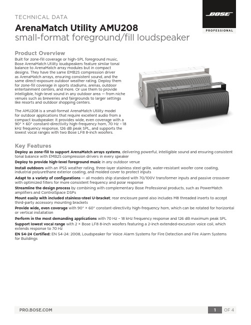
P R O F E S S I O N A LTECHNICAL DATAArenaMatch Utility AMU208small-format foreground/fill loudspeakerProduct OverviewBuilt for zone-fill coverage or high-SPL foreground music, Bose ArenaMatch Utility loudspeakers feature similar tonal balance to ArenaMatch array modules but in compact designs. They have the same EMB2S compression driver as ArenaMatch arrays, ensuring consistent sound, and the same direct-exposure outdoor weather rating. Deploy them for zone-fill coverage in sports stadiums, arenas, outdoor entertainment centers, and more. Or use them to provideintelligible, high-level sound in any outdoor area — from niche venues such as breweries and fairgrounds to larger settings like resorts and outdoor shopping centers.The AMU208 is a small-format ArenaMatch Utility model for outdoor applications that require excellent audio from a compact loudspeaker. It provides wide, even coverage with a 90° × 60° constant-directivity high-frequency horn, 70 Hz – 18 kHz frequency response, 126 dB peak SPL, and supports the lowest vocal ranges with two Bose LF8 8-inch woofers.Key FeaturesDeploy as zone-fill to support ArenaMatch arrays systems , delivering powerful, intelligible sound and ensuring consistent tonal balance with EMB2S compression drivers in every speaker Deploy to provide high-level foreground music in any outdoor venueInstall outdoors with an IP55 weather rating, three-layer stainless steel grille, water-resistant woofer cone coating, industrial polyurethane exterior coating, and molded cover to protect inputsAdapt to a variety of configurations — all models ship standard with 70/100V transformer inputs and passive crossover with optimized filters for more consistent frequency and polar responseStreamline the design process by combining with complementary Bose Professional products, such as PowerMatch amplifiers and ControlSpace DSPsMount easily with included stainless-steel U-bracket ; rear enclosure panel also includes M8 threaded inserts to accept third-party accessory mounting bracketsProvide wide, even coverage with 90° × 60° constant-directivity high-frequency horn, which can be rotated for horizontal or vertical installationPerform in the most demanding applications with 70 Hz – 18 kHz frequency response and 126 dB maximum peak SPL Support lowest vocal range with 2 × Bose LF8 8-inch woofers featuring a 2-inch extended-excursion voice coil, which extends response to 70 HzEN 54-24 Certified: EN 54-24: 2008, Loudspeaker for Voice Alarm Systems for Fire Detection and Fire Alarm Systems for BuildingsFootnotes(1) Frequency response and range measured on-axis in anechoic enviornment with recommended high-pass filter. Frequency response graphs display SPL axis with 0 dB line reference to sensitivity SPL value.(2) Bose extended-lifecycle test using pink noise filtered to meet IEC268-5, 6-dB crest factor, 500-hour duration. (3) AES standard 2-hour duration with IEC system noise. (4) Sensitivity measured in anechoic environment with recommended bandpass and EQ. (5) Maximum SPL calculated using sensitivity and power ratings, exlusive of power compression. (6) Tested to IP55 per EN60529 when used in General Purpose Audio installation.Technical SpecificationsFrequency ResponseFor additional specifications and application information, please visit . Specifications subject to change without notice. 03/2021。
桥梁术语英语词汇_xls

abrupt changing rhyme scheme突变韵律absolute type vibration transducer绝对式测振传感器abutment桥台abutment anchor bar桥台锚固栓钉abutment capping台帽abutment shaft台身accidental action偶然作用acid proof cement耐酸水泥acid rain酸雨acoustoelasticity声弹性法actions on bridge桥梁上的作用additional pile method加桩法additional strut beam method加撑梁法adjusting shaft校正井aerial remote sensing航空遥感aerodynamic model气流模型aerogeophysical prospecting航空物探aerophotography航空摄影aerophotography航片aesthetical ability审美能力aesthetical affection审美感受aesthetical appreciation审美评价aesthetical order审美序列aesthetical standard审美标准aesthetical taste审美趣味aesthetical treatment of bridge details桥梁细部美学处理aesthetical viewpoint审美观点age龄期aggregate interlock骨料咬合作用aggregate interlock集料aging of cold drawn bar冷拉时效air compressor空气压缩机air entraining agent加气剂air jet out let on outside wall of caisson井壁气龛air jetting method to reduce skin friction壁后压气法air spinning method空中纺缆法air vent排气孔air-entraining silicification method加气硅化法air-entrapping cement加气水泥air-lift dredger空气吸泥机airlock气闸Akashi Kaikyo Bridge明石海峡大桥Alcantara Bridge阿尔坎塔拉桥alkali liquid stabilization method碱液加固法allowable bearing capacity of foundation soil地基容许承载力allowable eccentricity of foundation base of bridge桥基底容许偏心alluvial deposit冲积层alluvium movement泥沙运动ALRT Bridge埃尔特桥alternate rhyme scheme交叉韵律alternatives比较方案aluminium-thermal spraying coating热喷铝涂层aluminum alloy steel bridge铝合金钢桥Alzette Bridge阿尔泽特桥ambient random vibration test环境随机激励振动试验Amizada Bridge埃米塞得桥analogy association类比联想analogy method比拟法anchor barge定位船anchor beam平衡梁anchor bearing plate锚垫板anchor bearing ring锚垫圈anchor by bond粘结锚anchor pile锚碇桩anchor plate锚碇板anchor span锚跨anchor span组合跨anchorage锚碇anchorage锚具anchorage for CCL prestressing system CCL体系锚具anchorage length锚固长度anchorage of rail线路锁定anchorage pier锚墩anchorage with ring plug环销锚anchorage with tapered plug锥销锚anchorage with wedges片销锚anchorage zone design锚下端块设计anchored bulkhead abutment锚锭板桥台anchored in rock piles嵌岩桩anchored pier锚固墩anchoring box锚箱angle steel角钢angular displacement of pier top墩顶转角angular transducer倾角仪Anlan Bridge安澜桥Annacis Island Bridge安纳西斯岛桥annual maximum instantaneous discharge年瞬时最大流量Anping Bridge安平桥antecedent rainfall前期降雨anti-creeper防爬器anticreeping angle防爬角钢antifreezing agent 防冻剂antirust welded steel bearing防锈焊接钢支座appraisal of rock section岩石薄片鉴定appreciation of beauty审美approach slab used at bridge end 桥头渡板approach span引桥appropriate reinforcement design适筋设计aqueduct bridge水渠桥arc hinge弧形铰arc plate bearing弧形钢板支座arch axis拱轴线arch bridge拱桥arch bridge with arch ring laid by cantilever method悬砌拱桥arch bridge with suspended road, through arch bridge下承式拱桥arch bridge with thrusts at supports有推力拱桥arch bridge with truss rib桁架肋拱桥arch bridge without thrusts at supports无推力拱桥arch centering拱架arch covering拱板arch crown拱顶arch culvert拱形涵洞arch disc bridge拱片桥arch hinge拱铰arch protection护拱arch rib拱肋arch ring拱圈arch seat拱座arch stone拱石arch tile拱波arch truss拱形桁架arched abutment拱形桥台areal rainfall面雨量Arrabida Bridge阿拉比德桥arrangement of culvert elevation涵洞的立面布置arrangement of piles in rank form桩的行列式排列artificial ground人工地基artificial loading method假载法artificial upper limit of frozen soil冻土人为上限assemblable truss拆装梁assembling bolt拼装螺栓assembling of member 杆件组装assembling pin冲钉assembling steel truss from members钢梁杆件拼装assembling steel truss on falsework脚手架上拼装钢梁association联想Astoria Bridge阿斯托里亚桥attribute of beauty美的属性Aue Bridge奥埃桥automatic welding自动焊auxiliary bridge for construction施工便桥auxiliary functions of bridge桥梁附加功能auxiliary pier辅助墩auxiliary pier method辅助墩法average discharge rate平均流量average discharge velocity平均流速axial bearing capacity of drilled caisson embedded in bedrock嵌岩管柱轴向承载力axial bearing capacity of piles桩轴向承载力axial compression strength of concrete混凝土轴心抗压强度Ba Bridge灞桥back of arch拱背back stayed abutment背撑式桥台Bailey bridge贝雷桥Baimianshi Bridge over Wushui River白面石武水大桥Baishatuo Changjiang (Yangtze) River Bridge at Chongqing重庆白沙砣长江大桥Baitashan Iron Bridge over Yellow River白塔山黄河铁桥balance weight abutment衡重式桥台balanced cantileuer construction均衡悬臂施工法balanced cantilever erecting crane for bridge spans双悬臂式架桥机balanced design平衡设计balanced failure界限破坏ballasted deck碎石铺装桥面ballasted deck bridge道碴桥面桥bamboo cable bridge笮桥bamboo cable bridge竹索桥bamboo reinforced concrete open caisson竹筋混凝土沉井band suspension displacement meter张线式位移计bank bar边滩Baodai Bridge宝带桥Baoding Bridge at Dukou渡口宝鼎桥barge驳船barrel arch bridge板拱桥Barrios de luna Bridge巴里奥斯·卢纳桥bascule bridge立转桥base-line survey基线测量basic rib基肋basic variable基本变量basic variable load基本可变荷载basic wind pressure基本风压basic wind speed基本风速basin流域Bauschinger effect of steel钢筋包辛格效应bay bridge海湾桥Bayonne Bridge贝永桥Bazi Bridge八字桥BBRV anchorage BBRV镦头锚BBRV wire posttensioning system BBRV体系beam bridge梁式桥beam bridge with wavy cross-section波形截面梁桥beam bridge without ballast无碴梁桥beam lowering落梁beam on elastic foundation analogy弹性地基梁比拟法beam-frame system rigid frame bridge梁-框体系刚架桥bearing支座bearing in butt joint正接抵承bearing member承重构件bearing of the hole-side钉孔承压bearing stiffener, end stiffener端加劲肋bearing stratum 持力层bearing stress of timber木材承压应力bearing structure承重结构bearing template, bed block支承垫石beauty of bridge body主体美beauty of bridge configuration桥梁造型美beauty of bridge decoration装饰美beauty of content内涵美beauty of form形式美bed for structure test结构试验台座bed load推移质bed material 河床质bed rock基岩bed shear河底切力bed-load transport推移质输沙率bedrock mark基岩标behavior test of prestressing anchorage预应力锚具性能试验Beida Friendship Bridge at Dalian大连市北大友谊桥Beipei Chaoyang Bridge at Chongqing重庆市北碚朝阳桥belt conveyor带式输送机benchland stage平滩水位benchmark (B.M.)水准点benchmark leveling基平bend test of bars钢筋冷弯试验bending plasticity of timber木材的弯曲塑性bending-up of flexural reinforcement钢筋的弯起Bendorf Bridge 本道夫桥bent cap. Capping盖梁bent structure排架结构bent-up bar弯起钢筋biaxial stress behavior of concrete混凝土双轴应力性能bidding, enter a bid投标bi-prestressing system concrete bridge双预应力体系混凝土桥bituminous deck pavement沥青铺装桥面bituminous surface treatment沥青表面处置blade bit刮刀钻头bleeding of concrete泌水blind ditch盲沟blind drain behind abutment, blind ditch behind abutment桥台后排水盲沟blind peariform anchorage暗藏梨状锚block砌块block for seismic protection防震挡块boat bridge舟桥bolt and nail connection栓钉结合bolt and weld connection栓焊连接bolt connection普通螺栓连接bolt tension calibrator螺栓轴力计bolted and welded steel truss bridge栓焊钢桁架桥bond failure mechanism粘结破坏机理bond stress粘结应力bond test for reinforcing bars钢筋握裹力试验Bonhomme Bridge博诺姆桥bored cast-in-situ pile钻孔灌注桩bored cast-in-situ pile with casing带套管钻孔灌注桩bored-inserting method钻孔插入法boring and grouting method钻孔灌浆法boring machine for cast-in-place piles灌注桩钻机Bosporus Bridge博斯普鲁斯桥Bosporus-Ⅱ Bridge博斯普鲁斯二桥boundary layer wind tunnel 大气边界层风洞boundary line of bridge construction, clearance of bridge constru桥梁建筑限界bowstring arch bridge, tied-arch bridge系杆拱桥box abutment箱形桥台box culvert箱形涵洞box frame bridge箱形桥box girder箱梁box girder bridge箱形梁桥box girder bridge with inclinedweb plate斜腹板箱梁桥box girder bridge with steel deck slab钢桥面板箱梁桥box girder with multiple cells多室箱梁box-ribbed arch bridge箱形拱桥brace拉条bracket牛腿bracket against a pier墩旁托架braided river游荡型河流braking bracing, braking frame制动撑架braking force and tractive force制动力和牵引力braking pier, abutment pier制动墩Brazo Largo Bridge布拉佐·拉戈桥break joint错缝brick culvert砖涵bridge桥梁bridge aerodynamic shape桥梁气动外形bridge aerodynamics桥梁空气动力学bridge aesthetics桥梁美学bridge and culvert桥涵bridge axis profile桥轴断面图bridge buffeting桥梁抖振bridge covering桥屋bridge crane桥式起重机bridge crossing structure over river桥渡bridge deck桥面bridge decoration桥上装饰bridge design procedure (program)桥梁设计程序bridge erecting crane架桥机bridge flutter桥梁颤振bridge foundation桥梁基础bridge layout in plan桥梁平面布置bridge lighting桥上照明bridge loadings, load on bridge桥梁荷载bridge maintenance gang养桥工区bridge member桥梁构件bridge planning design桥梁规划设计bridge project桥梁建设项目bridge project construction depth of bridge桥梁建筑高度bridge railing桥栏bridge rehabilitation桥梁修复bridge site桥位bridge site engineering survey桥位工程测量bridge site hydrographic plan桥渡水文平面图bridge site profile桥址纵断面图bridge site reconnaissance and topographic survey桥址勘测bridge site topographic map桥址地形图bridge sleeper桥忱bridge sleeper grooving桥枕刻槽bridge staircase桥梯bridge structure design method桥梁结构设计方法bridge tower桥塔bridge vortex-excited resonance桥梁涡激共振bridge with open floor明桥面桥Briesle Mass Bridge布里斯勒·玛斯桥Brinell hardness布林奈尔硬度brittle fracture of steel钢的脆断brittle-coating method脆性涂层法broken joint断缝Brooklyn Bridge布鲁克林桥Brotonne Bridge布鲁东纳桥Bubiyan Bridge布比延桥bucket elevator斗式提升机buckling coefficient of plate翘曲系数buckling load of column, buckling load压屈荷载buckling of plate钢板翘曲budget of working-drawings of a project施工图预算budget quota of bridge construction桥梁工程预算定额buildings at ends of bridge proper桥头建筑built-up formwork组合模板built-up section member组合杆件bulk cement truck散装水泥车bunched rails轨束梁bundle of I-beams工字梁束bundled girder束合大梁buoyancy of water水浮力buoyant box浮箱buried abutment埋置式桥台buried framed abutment框架埋置式桥台buried pile-column abutment桩柱埋置式桥强buried rib abutment肋形埋置式桥台buried river地下暗河burlap cofferdam麻袋围堰burring 除剌butt joint对接接头butt weld对接焊缝butt welder for reinforcing steel钢筋对焊机butt welding对接焊buttonhead anchorage镦头锚bybrid overflow pavement混合式过水路面c critical gradient临界坡度cable clamp索夹cable compaction紧缆cable crane缆索起重机cable net bridge索网桥cable protection斜缆防护cable saddle索鞍cable stayed bridge斜拉桥cable stayed bridge of multi-cable system密索体系斜拉桥cable stayed bridge with a single central cable plane单索面斜拉桥cable stayed bridge with continuous girder连续梁式斜拉桥cable stayed bridge with continuous rigid frame连续刚构式斜拉桥cable stayed bridge with double inclined cable planes双斜索面斜拉桥cable stayed bridge with double vertical cable planes双铅垂索面斜拉桥cable stayed bridge with rigid stays刚性索斜拉桥cable stayed bridge with single-cantilever girders单悬臂梁式斜拉桥cable stayed bridge with T-shaped rigid frames T形刚构式斜拉桥cable supported bridge缆索承重桥cable system being stable of the first order一阶稳定缆索体系cable system being stable of the second order二阶稳定缆索体系cable tower索塔cable with stranded wires钢绞线索cable wrapping缰丝cable-stayed bridge with composite girder钢结合梁斜拉桥caisson disease沉箱病caisson pile沉井型桩calcium silicate cement. Portland cement硅酸盐水泥calculated rise计算矢高calculating width of pile桩的计算宽度calculation of distortion by influence line用影响线计算畸变calling for tenders招标calm impression of force力的镇静camber上拱度camber预拱度canal bridge运河桥cantilever arch悬壁拱cantilever beam bridge悬臂梁桥cantilever concreting悬臂浇筑法cantilever construction method悬臂施工法cantilever erection悬臂拼装法cantilever method for assembling steel truss钢梁悬臂拼装法cantilever span悬臂跨cantilever truss bridge悬臂桁架梁桥cantilever truss construction method悬臂桁架法cantilever trussed arch bridge悬臂桁架拱桥cantilevered pier悬臂式桥墩cantilevered slab悬壁板cantilevered slab of deck trough confiing ballast道碴槽悬臂板cap of open caisson沉井顶盖capacitance type displacement transducer电容式位移传感器carbon equivalent [Ceq]碳当量carbon steel wire碳素钢丝cardborad drain method纸板排水法carriageway行车道carriageway beam行车道梁casing boring machine套管钻机casing method箍套法casing pipe护筒cast iron bridge铸铁桥cast steel bearing铸钢支座cast-in-place pile with variable cross-section变截面灌注桩cast-in-place reinforced concrete beam bridge就地浇筑钢筋混凝土梁桥cast-in-situ pile就地灌注桩catastrophic flood特大洪水catastrophic flood特大洪水处理catchment gutter聚水槽catenarian arch axis悬链线拱轴catenary arch bridge悬链线拱桥cathodic protection (cp) of steel bar钢筋阴极防腐法catwalk猫道cause and effect association因果联想cellular cofferdam of steel sheet pile构体式钢板桩围堰cement grouting method水泥灌浆法cement mortar mixer水泥砂浆搅拌机cement mortar pump水泥砂浆输送泵cement stabilized soil method水泥加固土法center of rainstorm暴雨中心center-hole jack穿心式千斤顶central span中孔centrifugal compacting process for reinforced concrete pipe-pile混凝土管桩离心法成型centrifugal force离心力centrifugal pump离心泵chain block链条滑车Changjiang (Yangtze) River Bridge at Nanjing南京长江大桥Changjiang (Yangtze) River Bridge at Wuhan武汉长江大桥Changjiang (Yangtze) River Bridge at Zhicheng枝城长江大桥Changjinag (Yangtze) River Bridge at Jiujiang九江长江大桥channel bottom slope河底经降channel bridge河渠桥channel section槽钢Chao Phraya River Bridge湄南河桥character association性质联想characteristic crack width特征裂缝宽度characteristic load特征荷载characteristic value of an action作用特征值charge amplifier电荷放大器chassification of prestressed concrete预应力混凝土的分类check消力槛check dam. Mud avalanche retaining dyke谷坊check load验算荷载chemical analysis of water水样分析chemical churning process单管旋喷注浆法chemical consolidation化学防护chemical method of derusting化学除锈chemical stabilization method化学加固法Chezy coefficient谢基系数Chezy formula谢基公式chipped stone arch bridge料石拱桥Choisy-le-Roi Bridge舒瓦西-勒-鲁瓦桥chute滑道chute急流槽circular arch bridge圆弧拱桥circular load cell环箍式测力计circulation current环流clasp nail马钉class A partially prestressed concrete bridge A类部分预应力混凝土桥class B partially prestressed concrete bridge B类部分预应力混凝土桥cleaning borehole of cast-in-situ bored pile钻孔灌注桩清孔clear lane width行车道净宽clear span of bridge桥梁净跨clearance above bridge deck桥面净空clearance above highway bridge deck公路桥面净空限界clearance testing car限界检查车clearance widening on curve曲线上净空加宽client, proprietor建设单位climber爬升器climbing form爬模closed drainage system封闭式排水系统closed end pipe pile闭口端管桩Coalbrookdale Bridge煤溪谷桥coefficient of arch axis拱轴系数coefficient of buckling for reinforced concrete column钢筋混凝土柱的纵向弯曲系数coefficient of dynamic response动力响应系数coefficient of live-load increment活载发展系数coefficient of rivets or bolts铆钉或螺栓系数coefficient of runoff径流系数coefficient of secondary stress in section截面次应力系数coefficient of thermal expansion of concrete混凝土热膨胀系数coefficient of variation of arch thickness拱厚变换系数coefficient of working live load运行活载系数cofferdam围堰cofferdam on the top of open caisson井顶围堰coherent coefficient of pier (T)墩的相干系数Tcohesive soil foundation粘性土地基coincide ratio of rivet hole钉孔通过率cold bending冷弯cold drawing machine for reinforcing steel钢筋冷拉机cold extruding machine for reinforcing steel and wire钢筋冷拔机cold flow of timber木材的冷流cold upsetting machine for rein-forcing steel and wire钢筋冷镦机cold-drawn low-carbon steel wire冷拔低碳钢丝cold-drawn rebar冷拉钢筋cold-drawn steel wire冷拔钢丝cold-rolled threadend anchorage轧丝锚cold-twisted rebar冷扭钢筋cold-worked bar冷作钢筋collapse崩塌colonnade foundation embedded in bedrock嵌岩管柱基础colour色彩column bent pier排柱式桥墩columnar pier柱式桥墩combination beam bridge with flat curved slab微弯板组合梁桥combination of load荷载组合combined beam bridge组合式梁桥combined braced system组合式撑架体系combined bridge, highway and railway bridge公路铁路两用桥combined end-bearing and friction pile中间型桩combined erecting equipment for bridge spans联合架桥机combined estimate index综合概算指标combined suspension and cable stayed bridge悬拉桥combined-system arch bridge组合体系拱桥combining value of actions作用组合值commercial function of bridge商业性桥梁Commodore J. Barry Bridge考莫多尔桥common compensated strain gauge公共补偿片compatibility相容性compatibility calculation相容性计算compatibility torsion协调扭转competitive tender of design scheme设计方案竞标complete correlation, function correlation完全相关completely probabilistic method全概率法complex type section of stream bed河床复式断面composite abutment组合式桥台composite beam bridge结合梁桥composite beam bridge组合式板桥composite box girder bridge组合箱梁桥composite expansion joint组合式伸缩缝composite girder复合大梁composite pile混合桩comprehensive unit price综合单价compressed-air floating caissons气筒浮式沉井compression failure of an over-reinforced member超筋破坏compression field theory压力场理论compression of soil土的压缩性compressive plasticity of timber木材压缩塑性compressive strength inclined to grain斜纹抗压强度compressive strength of concrete混凝土抗压强度compressive strength of reinforced concrete column钢筋混凝土柱的抗压强度compressive strength parallel to grain顺纹抗压强度compressive strength perpendicular to grain横纹抗压强度computation of temperature difference温差计算concealed pin暗销concealed work隐蔽工程concordant tendon吻合索concrete arch bridge混凝土拱桥concrete bridge混凝土桥concrete foundation of pier and abutment混凝土墩台基础concrete grades混凝土强度等级concrete hinged bearing混凝土铰支座concrete mixer混凝土搅拌机concrete mobile unit汽车式混凝土搅拌设备concrete open caisson混凝土沉井concrete placing boom混凝土布料杆concrete placing bucket混凝土吊斗concrete plant混凝土工厂concrete protective covering for rive bed混凝土护底concrete pump混凝土泵concrete slump cone混凝土坍落度简concrete truck mixer混凝土搅拌输送车concrete vibrator混凝土振捣器conductor for assembling组装胎型cone exploration锥探cone penetration test触探cone-anchorage jack锥式千斤顶confined concrete约束混凝土confined water承压水conic pitching of abutment桥台护锥conical pitching, conical revetment锥体护坡connecting line bridge across the strait跨海联络桥connection for built-up sections缀连性连接connection of steel bridge钢桥连接constant cross-section pier等截面桥墩construction budget, construction estimate施工预算construction cost, construction expenses工程费construction details施工详图construction error施工误差construction joint of concrete混凝土施工缝construction of bridge piers and abutments桥梁墩台施工construction specification施工规范constructional bar构造钢筋constructional loading施工荷载constuction with travelling formwork移动模架法contact stress beneath foundation基础接触应力contact type displacement measurement接触式位移测量continental river内陆河流continuity equation of constant flow (stationary flow)恒定流连续方程continuity stresses外约束应力continuous arch analysis连拱计算continuous arch bridge连续拱桥continuous beam bridge连续梁桥continuous conveyor连续输送机continuous deck method连续桥面法continuous pad built-up section member连续垫板组合杆件continuous rail无缝线路continuous rhyme scheme连续韵律continuous rigid frame bridge连续刚构桥continuous slab bridge连续板桥continuous-hinged rigid frame bridge连续铰接刚构桥contract of construction施工承包contraction coefficient收缩系数contractor, construction unit施工单位Contrasting method对比法conversion stress, equivalent stress换算应力coping, pier capping墩帽corner connection角接头corner joint隅节点corner stiffener隅加劲corner stiffening plate肱板correction for temperature effect温度修正correlation analysis相关分析correlation coefficient相关系数correlation of zero零相关corridor bridge廊桥corrosion-resistant steel bridge耐蚀钢桥corrugated metal pipe culvert波纹铁管涵cost of construction management施工管理费counter weight平衡重counterfort abutment扶壁式桥台coupler for tendons预应力筋连接器crack chart of structure结构裂缝图crack control裂缝控制cracking moment开裂弯矩crawler crane履带起重机creep camber徐变拱creep coefficient of concrete混凝土徐变系数creep limit of timber木材蠕变极限creep of concrete混凝土徐变creep of timber木材的蠕变creep of track轨道爬行criterion of similarty相似判据critical buckling load for reinforced concrete column钢筋混凝土柱的临界压力critical depth of flow临界水深critical flow临界流critical load of steel column钢压杆临界荷载critical relative compression depth界限相对受压区高度critical section临界断面critical speed临界速度critical velocity极限速度critical velocity of flow临界流速cross beam, floor beam横梁cross bracing 交叉撑架Cross Form Bridge鱼沼飞梁cross-section of stream河流横断面cross-sectional profile横断面图cross-wind galloping横风驰振crushing strength at elastic limit of timber木材弹性极限压碎强度crystallographic symmetry结晶对称cubic compressive strength of concrete混凝土立方体抗压强度culvert涵洞culvert abutment涵台culvert body涵洞洞身culvert foundation涵洞基础culvert grade涵底坡度culvert inlet and outlet涵洞洞口culvert inlet with flared wing wall八字翼墙洞口culvert location涵位culvert outlet erosion protection洞口冲刷防护culvert with steep grade陡坡涵洞culvert with top-fill暗涵culvert without top-fill明涵curb缘石curing by ponding围水养护curing of concrete混凝土养护current meter流速仪curve sign曲线标志curved bridge弯桥cut-off flow dike 截水坝cut-off wall截水墙cutting切割cutting edge of open caisson沉井刃脚cycle of incremental launching顶推循环dam bridge, gate bridge水闸桥Dames-Point Bridge达姆岬桥data logging system数据采集和处理系统datum level of elevation高程基准面Dazi Bridge over Lasa River, Xizang西藏拉萨河达孜桥dead load恒载debris flow泥石流deck bridge上承式桥deck construction桥面构造deck drainage桥面排水deck elevation桥面标高deck pavement桥面铺装deck slab桥面板deck slab行车道板deck truss girder bridge上承式桁架梁桥deck type arch bridge上承式拱桥decompression moment消压弯矩deduct losses扣损deep diving equipment深潜水设备deep foundation深基础deep mixing method深层搅拌法deep-reach深槽defective rivets不良铆钉defensive function of bridge防御性桥梁deflection theory挠度理论deflector导流板deformation joint 变形缝deformed bar变形钢筋degradation and sedimentation at meander reach of river河弯冲淤degree of prestressign, degree of prestress预应力度delivery with idler car游车发运depression detention填洼depth of matural flow天然水深derailment force掉道荷载derrick crane桅杆起重机derusting machine for reinforcing steel钢筋除锈机derusting of steel girder钢梁除锈derusting with steel wire brush钢刷除锈design approximate estimate设计概算design criteria设计准则design department, design section设计单位design discharge rate设计流量design discharge velocity设计流速design flood设计洪水design flood frequency设计洪水频率design life, designed service life设计寿命design load设计荷载design load spectrum设计荷载谱design of bridge cross-section桥梁横断面设计design of bridge opening孔径设计design of bridge profile桥梁纵断面设计design of loading products up-on a wagon成品装车设计design rainstorm设计暴雨design reference period设计基准期design stages, design phases设计阶段design stress spectrum 设计应力谱design stress-strain curve设计应力-应变曲线design water level设计水位design wind speed设计风速destructive test of structures结构破坏性试验detachable bridge for highway装配式公路钢桥detachable pneumatic caisson可撤式沉箱detachable truss for railway铁路拆装式桁梁deterministic design method定值设计法detour bridge便桥deviated flow斜流deviation coefficient C v变差系数 C vdiagonal斜杆diagonal crack, diagonal tension crack斜裂缝diagonal strut斜撑dial gauge百分表dial gauge千分表dial gauge with strain gauge transducer机电百分表diaphragm横隔板diaphragm wall equipment地下墙钻机diaphragm-wall bridge foundation地下连续墙桥基diesel hammer柴油锤differential transformer type displacement transducer差动变压器式位移传感器differential-acting steam hammer差动汽锤differentio-integral amplifier微积分放大器dimension量纲dimensional analysis量纲分析direct charges, direct cost直接费direct solar radiation太阳直接辐射direct-circulation drill正循环钻机discharge流量discharge at benchland stage平滩流量discharge for unit width单宽流量discharge velocity流速displacement at the top of pier or abutment墩(台)顶位移displacement of pier and abutment墩台变位displacement of pier head under the effect of sunshine日照作用下的墩顶位移displacement restriction equipment位移限制装置distorted model变态模型distortion畸变distribution of stream velocity in profile断面流速分布distribution of temperature difference温差分布distribution reinforcement分布钢筋dive drilling method潜水钻孔法diverging lane分车道diving appliances and equipment潜水设备Dizful Bridge提斯孚尔桥dominant discharge, formative discharge造床流量double cantilever beam bridge双悬臂梁桥double -columns pier双柱式桥墩double deck双层桥面double deck box-girder bridge双层箱梁桥double modulus theory双模量理论double pylon cable stayed bridge双塔式斜拉桥double shear双剪double-acting steam hammer双动汽锤double-hinged rigid frame bridge双铰刚架桥double-wall cofferdam of steel sheet pile双层钢板桩围堰double-wall cofferdam of timber sheet pile双层木板桩围堰double-webbed box girder bridge双腹板箱梁桥doubly reinforced section双筋截面doule-action jack双作用千斤顶dowel action销栓作用down hand welding俯焊drainage and waterproof system排水防水系统drainage channel排水槽drainage opening泄水孔drainage opening泄水口drainage pipe泄水管drainage pipe-line排水管道drainage pipe-line泄水管道drainage slope on pier-top墩顶排水坡dredging well沉井取土井dredging with hydraulic equipment in pneumatic caisson沉箱水力机械挖泥drill bit钻头drilled caisson管柱drilling钻探drilling after hand marking号孔钻孔drilling after welding后孔法drilling auger螺旋钻机drilling bucket回转斗钻机drilling mud钻孔泥浆dripping nose滴水driveway slab车道板drop dam跌水坝drop hammer落锤dry bridge旱桥dry joint干接缝duct孔道ductility of steel钢材的韧性Düisbrig-Neuenkamp Bridge杜伊斯堡-诺因坎普桥duplicate rhyme scheme重复韵律durability耐久性duration of flow concentration汇流历时dush jet mixing method粉体喷射搅拌法Dusseldorf-flehe Bridge杜塞多尔夫-弗勒埃桥Dusseldorf-Neuss Bridge杜塞尔多夫·诺依斯桥dynamic动态对称dynamic action动态作用dynamic balance动态平衡dynamic beauty动态美dynamic consolidation强夯法dynamic factor动力系数dynamic ice pressure动态冰压力dynamic modulus of elasticity of timber木材的动弹性模量dynamic photoelasticity动态光弹性法dynamic pile test桩动力试验dynamic resistance strain gauge动态电阻应变仪dynamic response动力响应dynamic response动力效应dynamic signal analyzer动态信号分析仪dynamic test of pile桩基动力试验dynamic test of structures 结构动载(力)试验Dywidag anchorage迪维达克锚具Dywidag threadbar posttensioning system迪维达克体系Eads Bridge伊兹桥early strength component早强剂earth pressure静止土压力earth pressure due to live load活载产生的土压力earthquake地震earthquake focus震源earthquake intensity地震烈度earthquake load, seismic action地震荷载earthquake magnitude地震震级earthquake simulation地震模拟振动台earthquake wave地震波East-Huntington Bridge东享廷顿桥eccentric compression method偏心受压法eccentrically loaded columns偏心受压柱eccentricity magnification factor for reinforced concrete column钢筋混凝土柱的偏心距增大系数economical span length经济跨径economy of bridge widening桥梁加宽经济性economy-technique index经济技术指标eddy-current type displacement transducer电涡流式位移传感器edge milling铣边edge planing刨边edge processing边缘加工effect due to change of temperature温度变化影响effect due to differential settlement of foundation基础不均匀沉降影响effect of concrete creep on thermal response混凝土徐变对热效应的影响effect of cracking on thermal response裂缝对热效应的影响effect of tension stiffening拉区强化效应effective coefficient of cost费用有效系数effective flange width有效翼缘宽度effective length at the end of nail钉端钳制长度effective prestress有效预应力effective slenderness ratio换算长细比effective span length有效跨径effects of actions作用效应elastic after-effect of timber木材弹性后效elastic buckling弹性屈曲elastic buckling of plate弹性翘曲elastic compliance of timber木材弹性柔量elastic constant of pier墩的弹性常数elasto-plastic bucking弹塑性屈曲elasto-plastic bucking of plate弹塑性翘曲electric hoist电动滑车electric impact method电力冲击法electric oil pump电动油泵electric winch电动卷扬机electrical measurement of non-electric quantities非电量电测技术electrical prospecting电法勘探electro silicification method电动硅化法electrodynamical vibration exciter电动式激振器electrodynamical vibration table电动式振动台electro-hydraulic servo fatigue test machine电液伺服式疲劳试验机electro-hydraulic vibration exciter电液式激振器electro-hydraulic vibration table电动液压式振动台electro-osmotic consolidation method电渗固结法elevated line bridge高架线路桥elevated monorail bridge高架单轨铁路桥elevating jack提升千斤顶elevation of base of foundation基底标高elevation of culvert涵底标高elevation of rail base轨底标高elevation of springing拱趾标高eluvium残积层embedded steel预埋钢筋emergency bridge紧急抢险桥empirical frequency经验频率empirical frequency curve经验频率曲线empty and real虚实end bearing colonnade foundation端承式管柱基础end bearing pile, point bearing pile支承桩end diagonal端斜杆end resistance of pile桩端阻力end zone splitting锚下端块劈裂endurance limit持久极限endurance strength of timber 木材持久强度energy input线能量energy rate of section断面比能engineering barge工程船舶engineering geology工程地质enlarged culvert inlet流线型洞口entrance of bridge桥梁入口epicenter震中epicentral distance震中距epoxy resin joint环氧树脂水泥胶接缝equal strength beam等强度梁equiamplitude fatigue tester等幅疲劳试验机equilibrium bifurcation平衡分叉equilibrium torsion平衡扭转equiponderant coefficient for live-load increment活载发展均衡系数equivalent length for bridge maintenance桥梁换算长度equivalent loading of highway公路等代荷载equivalent uniformly distributed live load换算均布活载。
Origin Effects BassRig Super Vintage 2 使用手册说明书

OWNER’S MANUALVersion 1.0ORIGIN EFFECTS® is a registered trademark of Origin Effects Limited.All other product names and trademarks are the propertyof their respective owners and are hereby acknowledged.AMPEG® is a registered trademark of Yamaha Guitar Group, Inc.Origin Effects has no affiliation with Yamaha Guitar Group, Inc.SVT® is a registered trademark of Yamaha Guitar Group, Inc.Origin Effects has no affiliation with Yamaha Guitar Group, Inc.No part of this publication may be reproduced in any form or by any means, whethermechanical or electronic, without the written permission of Origin Effects Limited.Origin Effects Limited reserves the right to change the features and specifications described herein without notice or obligation. Origin Effects Limited cannot be held responsible for any loss or damage arising directly or indirectly from any error or omission in this manual.PLEASE READ ALL INSTRUCTIONS, PAY ATTENTION TO SAFETY WARNINGS.Document version 1.0© Origin Effects Limited 2022IMPORTANT:This product is designed to be powered from a 9VDC, >150mApower supply with 2.1mm centre-negative barrel connector.ContentsIntroducing the BASSRIG SUPER VINTAGE (4)Connecting the BASSRIG SUPER VINTAGE (5)Main Controls (5)Main Controls (continued) (6)Using the DI OUT: (7)Setting your AMP OUT EQ: (8)Sample Settings (9)Sample Settings (continued) (10)Appendix A: Physical Specification (11)Appendix B: Performance Specification (11)Appendix C: Connector Pin Out (11)Appendix D: Safety Notices (12)Appendix E: Warranty (13)Introducing the BASSRIG SUPER VINTAGEThe BASSRIG Super Vintage is an all-analogue amp recreation and overdrive pedal, based on the legendary Ampeg® SVT® valve bass amp and its unmistakable 8x10 speaker cabinet. Introduced in 1969, the SVT®was the first purpose-built, high-powered bass amp, designed to fill big stages. It set a new standard for bass amplification and remains the first choice for many of the world’s most respected players. The BASSRIG Super Vintage recreates the sound, feel and character of this revolutionary bass rig.Familiar, responsive controls let you dial in instantly recognisable vintage and modern tones, from deep soul and funk to growling rock and metal, while the BLEND control adds in clean signal for low-end clarity and extra articulation.Our powerful AMP OUT EQ tailors the voicing of the pedal to suit any amp and cab, never compromising your clean tone, and the cabinet-simulated DI OUT means you don’t need to use an amp at all – the perfect bass tone, direct to your PA or studio console.The BASSRIG Super Vintage gives you the world’s biggest bass amp tones in a pedal you can take anywhere.Key Features:All-Analogue Amp Recreation In-cluding:• Full valve amp-style signal path recreated using discrete, transistor-based circuitry• Push-pull output section with reactive load, simulating interaction between amp and speaker • Analogue 8x10 cabinet simulatorFlexible, intuitive controls:• Wide gain range, from clean to full-onsaturation• BLEND knob to mix in your dry signal• Powerful tone-shaping AMP OUT EQ Peerless Build Quality:• High-current, low-noise electronics • Ultra-high input impedance• High-quality buffered bypass• Advanced power supply filtering and protection• Premium components throughout • Designed and built in EnglandConnecting the BASSRIG SUPER VINTAGE9VDC: Connect a 9VDC 2.1mm centre-negative mains power adaptor (minimum 150mA).INSTR: Connect to your bass, guitar or other instrument.AMP OUT: Connect to your amp or power amp.DI OUT: Connect to your mixer, audio interface or PA system.Main ControlsDRIVE: The gain control functions exactly like the volume knob on a non-master-volume valve amp. Turn it clockwise for more gain, drive and distortion. Turn counterclockwise to clean things up.BLEND: This control blends in your clean signal in parallel with the recreated amp tone. Set the control fully clockwise then turn it counterclockwise to progressively mix in your original clean signal. This can help add definition to your tone, especially in the low end when using overdriven sounds.Main Controls (continued)OUTPUT: The output control sets the pedal’s overall output level. As it isn’t part of the BASSRIG’s recreated amp circuitry, the OUTPUT control won’t alter the pedal’s overdrive character. It simply lets you make it louder or quieter.TREBLE: Just like on the original Ampeg® SVT®, the tone controls are placed before the overdrive. Turning the TREBLE control up will not only increase top end but also change the character of the overdrive, making it grittier and more aggressive. Turning this control down will result in a warmer tone and softer overdrive.MIDRANGE: This control can cut or boost mids at three different frequencies. Cutting the lower frequencies, especially with clean sounds, will result in a clear, scooped tone. Boosting the higher mids with an overdriven sound can create some fierce, howling rock distortion.MIDRANGE switch: Selects the frequency affected by the MIDRANGE control (220Hz, 800Hz or 3kHz).BASS: This control adjusts the amount of low frequencies as well as how “tight” or “thick” overdriven tones are. In general, higher BASS settings work better with cleaner sounds, with some really deep tones available. Heavily overdriven sounds can benefit from having the BASS turned down, preventing the distortion from becoming too “wooly”. But there are no rules – use a clean sound with the BASS set low for a percussive ‘60s tone, or turn the DRIVE and BASS up and unleash some fuzzy mayhem!ULTRA HI/LO CUT switch: The ULTRA HI position behaves like a standard bright switch, adding extra high frequencies in the preamp. Its effect is reduced as the DRIVE is increased. The LO CUT position activates a high-pass filter in the preamp, removing some low frequencies before the drive. This helps overdriven sounds stay tight and defined.AMP OUT EQ ControlsThe post-drive AMP OUT EQ ensures compatibility with a wide range of amps and cabs. Instead of compromising your amp’s tone controls to suit the BASSRIG, set your amp for your preferred clean sound then use the EQ controls to adjust the pedal’s output accordingly (see tables on page 8).HORN CUT EQ switch: This switch engages a choice of low-pass filters for use with tweeter-equipped cabs. Even with the most modern, hi-fi cabs, this will allow the BASSRIG to produce a natural, smooth overdrive tone, without any harshness.Choose between 2kHz or 4kHz depending on the response of your cab, or disable it altogether (centre position) when using a cab without a tweeter.HF: This post-drive high frequency control cuts or boosts upper-mid and treble frequencies. This is perfect for adjusting the BASSRIG’s high-end response to match your clean tone, adding some vintage speaker character to a modern cab or fine-tuning the effect of the HORN CUT filter.LF: This post-drive low frequency control cuts or boosts bass frequencies. This is perfect for adjustingthe BASSRIG’s low-end response to match your clean tone, fattening up a small cab or taming excessive boominess in a big cab.Using the DI OUT:This balanced XLR output is equipped with a meticulously engineered analogue cabinet simulator, accu-rately capturing the response of the industry standard SVT® 8x10 speaker cabinet. Using this output gives you the complete sound of a vintage bass amp direct to your recording console or PA system. No amp required. The DI output is designed for compatibility with a wide range of microphone and line level inputs. Its output level is configured to prevent unwanted clipping at the mixer or interface to which the pedal is connected.DI CAB SIM switch: Lets you select whether the cabinet simulator is always on or only active when the pedal is engaged. Select FX if you want a completely clean DI signal when the pedal is bypassed. Select FX+BYP if you want to keep the cab sim on, even when the pedal is bypassed – for example: if you want to use the BASSRIG cab sim with other drive pedals.DI GROUND switch: Lifts the ground of the DI Output. This is necessary to avoid unwanted ground loop hum when connecting the BASSRIG to multiple pieces of equipment (e.g. a bass amp and a PA system). If you hear a hum when connecting the BASSRIG to two pieces of equipment, set this switch to LIFT.If you are only connecting the BASSRIG’s DI OUT, this should be set to GND. This switch does not affect the AMP OUT.Setting your AMP OUT EQ:Use the tables below to help you set up the BASSRIG Super Vintage for the first time with a new bass amplifier or flat-response device. Working through Steps 1 and 2 allows you to “set-and-forget” the AMP OUT EQ controls and move on to having fun dialling in your ideal tone with the main controls.Step 1: Set HORN CUT for the connected amp or deviceStep 2: Fine-tune the AMP OUT EQ with the HF and LF controls*Please note: the AMP OUT EQ is only applied to the AMP OUT jack. The DI OUT is not affected.Sample SettingsRAGING MACHINEA mid-forward, aggressive tone, heard on some of the greatest modern bass riffs. Plenty of DRIVE and a MIDRANGE boost at 800Hz give you clas-sic SVT ® distortion, while the BLEND knob and LO CUT switch keep things tight and defined.STADIUM STACKBright, crunchy and powerful, this stage-filling tone is the epitome of ‘70s classic rock. With a touch of overdrive, a boost at 3kHz and the ULTRA HI switch engaged, there is plenty of presence to balance out the chunky bass responseNEO SOULFULDeep, warm and punchy, this huge clean sound has massive low end all the character of a classic valve amp. Cutting a little MIDRANGE at 220Hz helps this fat tone sit perfectly in the mix, whether you’re plugged into an amp or using the 8x10 cab sim on the DI OUT.DISCO DRIVEBefore the hi-fi, scooped slap sounds we know today, there were the funk and disco bass tones of the late ‘70s and early ‘80s. Just on the edge of overdrive and with a big boost at 800Hz, this thick, gritty tone is never too much.DIRTY NINETIESA cranked SVT ® is a big part of the blown-out sounds of ‘90s heavy rock. With cranked DRIVE and BASS, and a howling 800Hz boost, this de-structive, grungy tone is kept just on the right side of mayhem by the LO CUT switch.Sample Settings (continued)Appendix A: Physical SpecificationAppendix B: Performance SpecificationAppendix C: Connector Pin OutDI OUT male XLR:Appendix D: Safety NoticesGeneral SafetyKeep these instructions and heed all warnings. Do not use this apparatus near water. Clean only witha dry cloth. Do not install near any heat sources such as radiators, heat registers, stoves or other apparatus (including amplifiers) that produce heat. Refer all servicing to qualified service personnel. When using an external power supply, use only attachments/accessories specified by Origin Effects. Protect the power cord from being walked on or pinched particularly at plugs, convenience receptacles, and the point where they exit from the apparatus. Do not defeat the safety purpose of the polarised or grounding-type plug. A polarised plug has two blades with one wider than the other. A grounding type plug has two blades and a third grounding prong. The wide blade or the third prong are provided for your safety. If the provided plug does not fit into your outlet, consult an electrician for replacement of the obsolete outlet. Unplug this apparatus during lightning storms or when unused for long periods of time.CAUTION! No user-servicable parts inside. In the event of damage to the unit service orrepair must be done by qualified service personnel only.This Product is CE compliant.This product is UKCA compliant.FCC CertificationThis equipment has been tested and found to comply with the limits for a Class B digital device, pursuant to part 15 of the FCC Rules. These limits are designed to provide reasonable protection against harmful interference in a residential installation. This equipment generates, uses and can radiate radio frequency energy and, if not installed and used in accordance with the instructions, may cause harmful interference to radio communications. However, there is no guarantee that interference will not occur in a particular installation. If this equipment does cause harmful interference to radio or television reception, whichcan be determined by turning the equipment off and on, the user is encouraged to try to correct the interference by one or more of the following measures:• Reorient or relocate the receiving antenna.• Increase the separation between the equipment and receiver.• Connect the equipment into an outlet on a circuit different from that to which the receiver is connected.• Consult the dealer or an experienced radio/TV technician for help.Appendix D: Safety Notices (continued)The crossed out wheely bin symbol indicates this product is classified as Waste Electricaland Electronic Equipment (WEEE) in the European Union and should not be discarded with household waste. Other territories may vary. Contact your local authority or OriginEffects for more information.This product conforms to the European Union’s directive 2011/EU on Restrictions ofHazardous Substances (RoHS).WARNING: This product can expose you to chemicals including nickel, which is known to the State of California to cause cancer. For more information, go to Evaluation of apparatus based on altitude not exceeding 2000m. There may be somepotential safety hazard if the apparatus is operated at altitude exceeding 2000m.Evaluation of apparatus based on temperate climate conditions only. There may be some potential safety hazard if the apparatus is operated in tropical climate conditions.Appendix E: WarrantyThis product is covered by a 2-year manufacturer’s warranty from the date of purchase. This applies only to original purchasers who have bought their product from an authorised Origin Effects dealer or directly from Origin Effects.All returns or servicing should be arranged through the original dealer. Proof of original ownership may be required in the form of a purchase receipt.For full warranty details visit /warranty .RoHS。
- 1、下载文档前请自行甄别文档内容的完整性,平台不提供额外的编辑、内容补充、找答案等附加服务。
- 2、"仅部分预览"的文档,不可在线预览部分如存在完整性等问题,可反馈申请退款(可完整预览的文档不适用该条件!)。
- 3、如文档侵犯您的权益,请联系客服反馈,我们会尽快为您处理(人工客服工作时间:9:00-18:30)。
abstract
This study examines the airside performance of the wavy fin-and-tube heat exchangers having a larger diameter tube (Dc = 16.59 mm) with the tube row ranging from 1 to 16. It is found that the effect of tube row on the heat transfer performance is quite significant, and the heat transfer performance deteriorates with the rise of tube row. The performance drop is especially pronounced at the low Reynolds number region. Actually more than 85% drop of heat transfer performance is seen for Fp $ 1.7 mm as the row number is increased from 1 to 16. Upon the influence of tube row on the frictional performance, an unexpected row dependence of the friction factor is encountered. The effect of fin pitch on the airside performance is comparatively small for N = 1 or N = 2. However, a notable drop of heat transfer performance is seen when the number of tube row is increased, and normally higher heat transfer and frictional performance is associated with that of the larger fin pitch.
Ó 2010 Elsevier Ltd. All rights reserved.
1. Introduction
Finned tube heat exchangers are very extensively used in various industrial applications. They are quite compact, light weight, and characterized by a relatively low cost fabrication. Normally the dominant resistance is on the airside; therefore the exploitation of enhanced fin surfaces is very common to effectively improve the overall heat transfer performance. Among the enhanced fin patterns, the herringbone wavy fin surface shown in Fig. 1 is one of the most popular surfaces since it can lengthen the airflow inside the heat exchanger and cause better mixing of the airflow.
⇑ Corresponding author. Address: Department of Mechanical Engineering,
National Chiao Tung University, EE474, 1001 University Road, Hsinchu 300, Taiwan. E-mail address: ccwang@.tw (C.-C. Wang).
The first comprehensive study related to the herringbone wavy fin pattern was done by Beecher and Fagan [1]. They presented test results for twenty-one herringbone fin-and-tube heat exchangers having N = 3. Data were presented in terms of Nusselt number, Nua, based on the arithmetic mean temperature difference (AMTD) vs. Graetz number. However, the wavy fin geometry tested by Beecher and Fagan [1] was rather uncommon when compared to practical design. Their fins were electrically heated, and thermocouples were embedded in the plates to determine the plate surface temperature. The power to the several electric heaters was adjusted to maintain a constant temperature over the airflow length. This simulated a fin-and-tube heat exchanger having 100% fin efficiency
a Department of Mechanical Engineering, National Chiao Tung University, Hsinchu 300, Taiwan b Green Energy and Environment Research Laboratories, Industrial Technology Research Institute, Hsinchu 310, Taiwan
0017-9310/$ - see front matter Ó 2010 Elsevier Ltd. All rights reserved. doi:10.1016/j.ijheatmasstransfer.2010.11.038
and zero contact resistance between the tube and fin. Webb [2] recasts the investigation of Beecher and Fagan [1], and developed the correlation.
journal homepage: /locate/ijhmt
Airside performance of herringbone wavy fin-and-tube heat exchangers – data with larger diameter tube
Chi-Chuan Wang a,⇑, Jane-Sunn Liaw b, Bing-Chwen Yang b
For commercial applications, large diameter tube about 16 mm is very popularly used in ventilator and fan-coil units. Unfortunately, very rare data were available for this kind of configuration. In this connection, it is the objective of this study to provide airside performance of this popular fin geometry and discuss the effect of fin pitch and tube row on the relevant performance.
article info
Article history: Received 25 August 2010 Received in revised form 23 October 2010 Accepted 23 October 2010 Available online 13 December 2010
A series investigation of the herringbone wavy fin patterns based on commercially available samples was conducted by Wang et al. [3–7], Chokeman and Wongwises [8], Wongwises and Chokeman [9], Kim et al. [10]. Effects of fin spacing, the number of tube row, wave height, fin pattern, fin thickness, and edge corrugation were systematically examined. Wang et al. [11] developed a general correlation based on their database. Their proposed correlation had a mean deviation of 6.98% for the heat transfer performance and a mean deviation of 8.82% for the friction factors. However, the foregoing data and correlations were mainly based on Pt = 25.4 mm and Pl = 19.05 mm with a tube size around 10 mm. Extrapolations of this correlation to other ranges of Pt and Pl are not recommended. Note that this kind of configuration is often used in small air-conditioning system.