定量分析凝汽器冷却水管结垢对机组经济性的影响
凝汽式汽轮机机组真空恶化原因分析及维护方法
凝汽式汽轮机机组真空恶化原因分析及维护方法摘要:凝汽式汽轮机真空度对机组实际生产过程中安全平稳运行起到了至关重要的作用。
因此,必须重视对其进行全面有效地控制与管理。
但由于多方面因素的限制,导致部分凝汽式汽轮机存在一定程度上的真空下降现象。
对此,需要采取针对性的控制措施。
从凝汽器系统,轴封系统和循环水系统3个角度分析了导致凝汽式汽轮机真空度下降的主要因素,从解决存在问题和加强检查维护等多个方面论述了解决凝汽式汽轮机真空下降的具体对策,以供参考。
关键词:凝汽式;汽轮机机组;真空恶化1热电企业凝汽式汽轮机运行过程中常会碰到真空逐步降低的情况,特别是在夏季凝汽器真空对于汽轮机运行经济性有很大影响,如果其他工况不发生变化,真空度每次改变1%,汽轮机汽耗率就会平均改变1%-2%。
由于真空降低,致使抽气量减小、排气温度增高和抽气量增加。
同时也导致凝结水含氧量增大、水质恶化等一系列不利现象发生。
因此,必须采取各种措施提高凝汽器真空。
不但使得机组能耗增加,影响机组的经济性,甚至会对机组的安全构成威胁,严重的还会减少发电负荷。
因此通常规定:当排汽压力上升至0.015Mpa时应减少负荷,当排汽压力增加至0.03Mpa附近时应完全卸除负荷,直到在规定工况下执行故障停机为止,这直接关系到企业经济效益。
而如果泄漏到空气中,不仅会使凝结水过冷,降低凝汽器除氧效果,使凝结水中溶入部分气体,导致凝结水系统设备和管道氧腐蚀而影响机组安全运行。
1凝汽器真空建立的原理凝汽器真空在机组启动阶段和正常运行时建立的机制不同。
机组启动后,凝汽器内真空的确立取决于真空泵对凝汽器内空气的抽离,这时真空确立的速度取决于真空泵容量和真空系统严密程度。
机组冲转时,有排汽流入凝汽器,排汽在冷却介质作用下冷凝为水。
水从排出口流出之后,温度升高;当水温达到一定程度,便开始凝结成水蒸气并释放出大量热能,从而使汽轮机转速提高。
乏汽冷凝成水后体积大为减小,原被蒸汽填充的容器空间内形成高度真空。
凝汽器铜管结垢可造成凝汽器铜管腐蚀分析及改造方案

凝汽器铜管结垢可造成凝汽器铜管腐蚀分析及改造方案1基本概况我司两台哈汽生产的150MW汽轮机组04年投产,单壳体、对分双流表面式凝汽器,主要由壳体、进出水室、后水室、前后管板、中间管板、冷却管和凝结水聚集器等组成,附属设备由进、出水蝶阀、胶球清洗装置等。
凝汽器壳体由钢板焊接而成,体内布置四组冷却管束,管束中间为空冷区,由此引出抽空气管,冷却管采用胀接固定。
凝汽器主要参数:冷却面积:8700m2;冷却管总数:*****根;冷却管材质:HSN70-1AB、Bfe30-1-1;冷却管规格:Φ25×1(主凝结区、空冷区),Φ25×1.5(顶部三排及通道外侧);水室设计压力:0.245MPa;凝汽器背压:0.0062MPa;循环水入口温度:25℃。
机组自投运以来,多次发现管口和胀口部位出现渗漏现象。
到08年初,泄漏的频率逐渐增加,泄漏铜管的数量也逐渐增多,泄漏量不断增大。
泄漏部位从管口向中间发展,还发生铜管从中间断裂现象。
据统计从2021年开始至2021年初,2台机组共发生过14次铜管泄漏。
刚开始还能靠加锯木屑堵漏,随着泄漏量不断增大,只能退出凝结器单边查漏,严重影响了机组的和经济运行。
2腐蚀原因分析我司位于珠江三角洲西部,生产用水都取自珠江支流潭江的银洲湖,离崖门出海口不足50公里。
银洲湖每天都会出现2次涨潮海水倒灌,这时江水的Clˉ含量大大超标。
一年中,有4个月Clˉ浓度超过2000mg/L。
近年来,每年年底都出现咸潮,导致循环冷却水Clˉ浓度最高可达6900mg/L。
研究表明,Clˉ对铜合金的腐蚀与钝化金属在含Clˉ溶液中的孔蚀机理一样,是Clˉ对表面膜的局部破坏而造成的,这种侵蚀主要表现为铜表面Cu2O被Clˉ侵蚀而生成CuCl。
这种侵蚀分两种情况:一种是铜表面保护膜处于婴儿期阶段的侵蚀2Cu+2Cl--2e→2CuCl→Cu2O+2HCl(阳极过程)另一种是铜表面保护膜处于成熟期阶段的侵蚀2CuCl→Cu+CuCl2CuCl+Cl-→CuCl2两类反应都会对铜表面膜造成破坏。
定量分析双背压凝汽器冷却水管结垢对机组经济性的影响

真 空 、 组 功 率 以及 机 组 热耗 率 的 影 响进 行 了 定 量分 析 计 算 。计 算 结果 表 明冷 却 水 管 结垢 会 严 重 地 影 响 凝 汽 器真 机 空及 机 组 的 运 行 经 济 性 , 算 所得 的研 究 结 果 , 提 高 采 用 双 背 压 凝 汽 器 的 大 型 机 组 的 运 行 经 济 性 有 着 重 要 的 现 计 对
实意 义和 指 导意 义 。
关 键 词 : 量 分 析 ; 背压 凝 汽 器 ; 却 水 管 ; 垢 ; 济性 定 双 冷 结 经 中 图分 类号 : K 2 4 1 1 T 6 . 文 献标 识 码 : A
Qu n i t eA ay i o h mp c n UntE o o t o l g a t ai n lss ft eI a t i c n mywi C oi t v o h n
W a e b u i fDu l x Pr s u e Co d ns r t r Tu e Fo lng o p e e s r n e e
X A u- n I 0 G oj u
( e I siue o eg n o rEn ie rn ,Hu z o ie s y o ce c n e h o o y,W u a Th n t t fEn r y a d P we g n e g t i a h n Unv ri fS i ea d T7 , ia b i 3 0 4 Chn )
更均 匀 的热负荷 分 布 、 好 的 冷却 效 果及 更 优 的经 更
前 言
凝汽 器是凝 汽 式 机 组 的重 要 组 成 部分 , 工作 其
状 况 的好 坏 , 直接 影 响着 整 个 机 组 运行 的安 全性 和 经济性 。由于双 背压凝 汽器 相对 于单 压凝汽 器具 有
浅谈凝结水过冷却对机组运行的影响
浅谈凝结水过冷却对机组运行的影响1、概述在凝结器内凝结水的出口温度低于蒸汽的饱和温度的现象称为凝结水过冷却,所低的度数称为过冷却度。
凝结水过冷增加了循环冷却水的耗量,使冷源损失增加,同时也增加了机组末级低加的回热抽汽量,使回热效率降低,影响了机组的经济性。
凝结水过度冷却,其含氧量就会大大增加,凝结水水质就会恶化,致使低压结水系统设备受到腐蚀,除氧器除氧负担加重,对机组的安全运行极为不利。
因此,过冷度的存在对机组运行的经济性和安全性都有不利影响。
从节能降耗和安全运行两方面考虑,降低凝结水的过冷度是十分必要的。
2、凝结水过冷原因分析凝结水过冷度表征凝结器热水井中凝结水的冷却程度,它是衡量凝结器经济运行的重要指标之一,目前对凝结器过冷度的要求是不超过0.5~1℃。
凝结水产生过冷的主要原因及影响因素是:2.1由于冷却水管管子外表面蒸汽分压力低于管束之间的蒸汽平均分压力,使蒸汽的凝结温度低于管束之间混合汽流的温度,从而产生过冷。
2.2由于凝结器内存在汽阻,蒸汽从排汽口向下部流动时遇到阻力,造成下部蒸汽压力低于上部压力,下部凝结水温度较上部低,从而产生过冷。
2.3蒸汽被冷却成液滴时,在凝结器冷却水管间流动,受管内循环水冷却,因液滴的温度比冷却水管管壁温度高,凝结水降温从而低于其饱和温度,产生过冷。
2.4 由于凝结器汽侧积有空气,空气分压力增大,蒸汽分压力相对降低,蒸汽仍在自己的分压力下凝结,使凝结水温度低于排汽温度,产生过冷。
2.5凝结器构造上存在缺陷,冷却水管束排列不合理,使凝结水在冷却水管外形成一层水膜,当水膜变厚下垂成水滴时,水滴的温度即水膜内、外层平均温度低于水膜外表面的饱和温度,从而产生过冷却。
2.6凝结器漏入空气多或抽气器工作不正常,空气不能及时被抽出,空气分压力增大,使过冷度增加。
2.7 热水井水位高于正常范围,凝结器部分铜管被淹没,使被淹没铜管中循环水带走一部分凝结水的热量而产生过冷却。
2.8循环水温度过低和循环水量过大,使凝结水被过度的冷却,过冷度增加。
凝汽器污垢对热经济性的影响
Energy and Buildings 50(2012)204–211Contents lists available at SciVerse ScienceDirectEnergy andBuildingsj o u r n a l h o m e p a g e :w w w.e l s e v i e r.c o m /l o c a t e /e n b u i ldExperimental determination of fouling factor on plate heat exchangers in district heating systemSrbislav B.Geni´c a ,∗,Branislav M.Ja´cimovi´c a ,Dragan Mandi´c b ,Dragan Petrovi´c aa Faculty of Mechanical Engineering,University of Belgrade,Kraljice Marije 16,11000Belgrade,Serbia bJKP Beogradske elektrane,Savski nasip 11,1070Belgrade,Serbiaa r t i c l ei n f oArticle history:Received 5March 2012Received in revised form 14March 2012Accepted 17March 2012Keywords:District heatingDomestic hot water Plate heat exchanger Fouling factora b s t r a c tThis paper presents the results of experimental research on 8plate heat exchangers.Their purpose is to heat water for radiator heating system and domestic hot water.Measurements were carried out in 4substations in district heating system in Belgrade (Serbia).The main achievement of this research was that the fouling factors were determined experimentally,and the found values can be used further on in design of plate heat exchangers in district heating systems.©2012Elsevier B.V.All rights reserved.1.IntroductionDomestic hot water (DHW)system is a part of district heating system in Belgrade (Serbia).JKP Beogradske elektrane (municipal company for district heating in Belgrade)continuously improves the system by incorporating prefabricated compact substations which serve two purposes:heating of water for radiator heating system and heating of DHW.Basically there are two ways of preparing hot water [1],and both have been applied in Belgrade:•the “old”system that included the accumulation tank in which hot water is stored.•the “new”system with instantaneous hot water production.The last option is of particular interest in this paper.DHW heaters,accompanied by the tap water filters,are the main part of this sys-tem.Nowadays,in Belgrade DHW system,practically only magnetic filters and plate heat exchangers are used,since their performances and prices are significantly favorable than performances and prices of tubular heat exchangers in this field of application.The total number of substations with DHW is 413with serve more than 34,000individual consumers.Overall heat duty for com-plete DHW system in Belgrade is 65.2MW,with nominal heat duties of individual substations in range 4.5–1070kW.∗Corresponding author.Tel.:+381113302360;fax:+381113370364.E-mail address:sgenic@mas.bg.ac.rs (S.B.Geni´c).This paper will describe the influence of water velocity on foul-ing factor in plate heat exchangers,based on measurements on 4district heating substations (DHS)in the Sector of the Heat Plant Zemun.2.Plate heat exchanger foulingDuring the operation of a heat exchanger,its heat duty reduces due to a phenomenon called fouling:the deposit of undesirable dirt on the heat exchange surfaces increases the resistance to heat transfer.Heat exchanger fouling is a very significant problem in heat exchanger exploitation,because still there is no reliable theoretical method for predicting the fouling phenomena and all relevant information are obtained by monitoring the changes in heat exchanger performance during the exploitation period [2].Based on these measured data it is possible,to a certain extent,to predict the behavior of apparatuses of similar design,at approx-imately the same exploitation conditions (identical working fluids,pressures and temperatures,velocities,etc.).Also,it is possible to predict the shut off period for cleaning of the heat exchanger.In general,working regime (fluid flow rate,temperature,pressure and concentration of components)as well as the actual plate geometry (shape of corrugations –angle,amplitude and wavelength)affects the formation of deposits [3–5].The overall heat transfer coefficient for plain wall is defined as1k =1˛1+R 1+ıpl pl+R 2+1˛2(1)where0378-7788/$–see front matter ©2012Elsevier B.V.All rights reserved.doi:10.1016/j.enbuild.2012.03.039S.B.Geni´c et al./Energy and Buildings50(2012)204–211205NomenclatureA channelflow area(flow area between plates),m2b meanflow channel gap(distance between plates),mCF cleanliness factorc p specific heat capacity at constant pressure,J/(kg K)CR correlation ratioDHW domestic hot waterDHS district heating substationsDM design margink overall heat transfer coefficient,W/(m2K)LMTD mean logarithmic temperature difference,◦CL length,m˙m massflow rate,kg/sN numberp plate pitch,m˙Q heat duty,WR fouling factor(resistance),m2K/WRMSD root-mean-square deviationRW radiator waterS heat transfer surface,m2t temperature,◦Cufluid velocity,m/sW plate width,m˛heat transfer coefficient,m2K/Wıthickness,mst unsteadiness of working regime(dispersion of heatduty)p pressure drop due to friction,Pathermal conductivity,W/(m K)(wall)shear stress,PaSubscripts1hotfluid2coldfluidav averagec clean(unfouled)in inletm meanout outletpl one platetot total•˛1and˛2are the heat transfer coefficients for hot and coldfluidsrespectively in W/(m2K);•R1and R2are the fouling resistances in m2K/W for hot and coldfluids respectively;•ıpl(m)and pl(W/(m K))are the thickness and thermal conduc-tivity of the plate.Total fouling factor(for plain wall)is defined asR tot=R1+R2=1k −1k c(2)where k c is the overall heat transfer coefficient for clean(unfouled) surfaces.In addition,there are other ways for expressing the fouling phe-nomena:•cleanliness factor[6]CF=kk c=11+R tot·k(3)Table1Recommended fouling resistances for plate and frame heat exchangers.Water R,m2K/kWDemineralized or distilled water0.009River water0.045Ocean or coastal sea water0.025–0.045Treated cooling tower water0.035–0.045Soft water0.018Hard water0.045•design margin[7]or heat transfer surface area margin(k-valuemargin)DM=k ck−1=R tot·k c=1CF−1(4)Regardless on the way the fouling resistance is expressed generallyspeaking it depends on heat transfer surface material,flow rates orvelocities and fouling affinity of thefluids.The usual approach to heat exchanger design is to include thefouling factors in(1).Fouling factors can be found in the open lit-erature[6,8–12],and selected values for water are presented inTable1.Other open literature sources claim the following:•most manufacturers of plate and frame heat exchangers recom-mend that the excess surface should not exceed25%of the heattransfer surface area calculated for the clean duty[2];•plate and frame heat exchangers fouling factors are typically1/10of TEMA values[13];•safe and proven fouling factors for plate heat exchanger designare10%excess surface area,also expressed as10%safety margin,equivalent to approximately(but not exactly)a cleanliness factorof90%[14];•“for a plate heat exchanger in a water/water duty a margin of0÷15%depending on water quality is normally enough”[7].In past few decades,wall shear stress became a significant parame-ter in fouling factor analysis,since it is a measure of thefluid stressalong the face of the corrugated plate.For example in[15]it is saidthat“Shear stress is the metric to evaluate fouling tendency,ratherthan absolute velocity.”Wall shear stress is defined as follows[14]= p·b2·L(5)where• p,Pa,is the pressure drop due to friction;•b,m,is the distance between plates;•L,m,is the effective plate length.The following recommendations about the influence of shearstress on fouling factor are found in the open literature:•greater shear stress provides the greater“resistance”to the depo-sition of particles[16]and this is the main reason that plate heatexchangers are characterized with smaller fouling factors thantubular heat exchangers;•according to[17]it is not recommended to size the heatexchanger with the shear stress below50Pa,and if there is asignificant risk of fouling it is recommended that the shear stressshould be increased to at least100Pa;•in[18]the experiment was conducted on heat exchanger with themixture of water and crushed ice and authors came to the con-clusion that the smooth operation of apparatus occurred when206S.B.Geni´c et al./Energy and Buildings 50(2012)204–211Fig.1.Process flow diagram of DHS.Table 2Codification of DHS and heat exchangers (type—number of plates).Address of DHS (street and number)DHS codeDHW heaterRW heaterBaˇc ka no.9A A-113C-222Zagorska no.12B A-89C-104Zagorska no.18–46C A-87C-152Prvomajska no.33DB-113C-200Table 3Design data of heat exchanger for DHW system.DHS codeABCDDHW heaterA-113A-89A-87B-113Number of plates,N pl 1138987113Number of active plates 1118785111Plate thickness,ıpl ,mm 0.60.6One plate surface,S pl ,m 20.040.0940Mean flow channel gap,b ,mm 0.96 1.0Plate width,W ,mm119243Flow area between plates,A pl ,m 20.0001140.000243Heat transfer surface,S ,m 24.443.487.9210.43>50Pa.The regimes with lesser values of were characterized with ice choking.3.Measurements and resultsThe objective of this research was to obtain accurate results on fouling resistances in plate heat exchangers for DHW system in Bel-grade.Substations discussed in this paper serve for two purposes:heating of water for radiator heating system as well as heating of DHW.Substations are located in a heating area of the Heat Plant Zemun in Belgrade (Serbia).A process flow diagram of DHS is pre-sented in Fig.1.Each substation was equipped with necessary control systems (valves,flow limiters,etc.),two heat exchangersTable 4Design data of heat exchanger for RW system.DHS codeABCD RW heaterC-222C-104C-152C-200Number of plates,N pl 222104200152Number of active plates 220102198150Plate thickness,ıpl ,mm 0.6One plate surface,S pl ,m 20.109Mean flow channel gap,b ,mm 2.44Plate width,W ,mm243Flow area between plates,A pl ,m 20.000593Heat transfer surface,S ,m 223.9811.121.516.35(basic data is given in Tables 2–4)and magnetic filters on the DHW pipeline.In all tested DHW heaters cold fluid was tap water,all appa-ratuses had counter-current flow,and each one of them was thermally insulated.Our laboratory holds the Accreditation Certificate for the follow-ing standards:•BS EN 305:1997Heat Exchangers:Definitions Of Performance Of Heat Exchangers And The General Test Procedure For Establishing Performance Of All Heat Exchangers;•BS EN 306:1997Heat Exchangers:Methods Of Measuring The Parameters Necessary For Establishing The Performance;•BS EN 307:1999Heat Exchangers:Guidelines For Preparing Installation,Operating And Maintenance Instructions Required To Maintain The Performance Of Each Type Of Heat Exchanger;so our measurements were performed according to proce-dures from these standards.For each heat exchanger the following parameters were measured:•˙m1,kg/s,mass flow rate of hot fluid;•t 1in ,◦C,inlet temperature of hot fluid;•t 1out ,◦C,outlet temperature of hot fluid;•˙m2,kg/s,mass flow rate of cold fluid;•t 2in ,◦C,inlet temperature of cold fluid;•t 2out ,◦C,outlet temperature of cold fluid.Measurements of water flow rate were performed with ultrasonic flow meters with the relative uncertainty of ±3%.Temperatures were measured using four platinum resistance thermometers (PT 100)with the maximal uncertainty of ±0.1◦C.Three heat duties of the heat exchanger could be determined from each set of test data:•heat duty calculated with measured values for the hot fluid˙Q1=˙m 1·c p 1·(t 1in −t 1out )(6)•heat duty calculated with measured values for the cold fluid˙Q2=˙m 2·c p 2·(t 2out −t 2in )(7)•mean value of heat duty˙Qm =˙Q 1+˙Q 22(8)where c p 1,J/(kg K)and c p 2,J/(kg K)are specific heat capacities of hot and cold fluids,respectively.S.B.Geni´c et al./Energy and Buildings 50(2012)204–211207The unsteadiness (dispersion of heat duty)of each workingregime is defined byst =(˙Q1−˙Q m )2+(˙Q 2−˙Q m )2˙Qm (9)In engineering practice it is commonly assumed that the disper-sion of 3–7%or even 10%in the heat balance is acceptable [19,20].Hereby,similarly to [21],further analysis of the fouling resistance was done only for the working regimes with st <10%.Since all the heat exchangers operated with the counter-current flow,the mean logarithmic temperature difference isLMTD =(t 1in −t 2out )−(t 1out −t 2in )lnt 1in −t 2out t 1out −t 2in(10)and the overall heat transfer coefficient isk =˙Q m S ·LMTD(11)The overall fouling thermal resistance (R tot )was calculated using (2).The overall heat transfer coefficient for the heat exchanger with clean (unfouled)heat transfer surfaces k c was calculated for each regime using the manufacturer’s design software.The experimental work was divided in two parts.First set of measurements was conducted shortly after the substation was con-nected to the heating system (about 5to 15days).These results are indicated using subscript Y 0.Second set of measurements was done a year later (subscript Y 1).During this one year period substations worked in the normal regime dictated by the heat plant,including a half year pause for RW heaters during the summer period.Table 5presents the results of measurements for RW heaters and Table 6presents the results of measurements for DHW heat exchangers.Fluid velocities u 1and u 2are based on flow area between plates,and refer to hot and cold fluids,respectively.4.DiscussionFor further discussion it is useful to calculate average values based on Tables 5and 6.Tables 7and 8contain the average values of u 1,av ,u 2,av ,R tot,av ,CF av ,and DM av .4.1.Fouling of radiator water heatersAnalyzing the data presented in Tables 5and 7it can be noticed that the both fluid velocities were very consistent during the test.Also,in one year period fouling resistances of 4heat exchang-ers did not change significantly (the increase R tot is close to the order of magnitude of measurement uncertainty)and ranged from R tot =0.082to 0.113m 2K/kW,i.e.R tot =0.096m 2K/kW with maxi-mal deviation of ±17%.This means that in heat exchanger design process the fouling resistance value of R tot =0.096m 2K/kW can be adopted as a statistically proven one.Average design margin changes over the greater range DM av =0.17–0.33and average cleanliness factor over a lesser range CF av =0.75–0.86,so it can be concluded that despite the conformity of usage of just one parameter like in case of DM or CF ,it is more rec-ommendable to use fouling resistance R in heat exchanger design,because it gives a more realistic physical insight into the fouling process.In further analysis of the fouling resistance it must be taken into account that the radiator heating system is filled with water from the magisterial pipelines.That means that both hot and cold water has approximately the same fouling characteristics,so it can be writtenR 1=R 2=R tot 2(14)Fig.2.DHW heaters—fouling factor vs.hot fluid velocity.and the fouling resistances R 1=R 2=0.048m 2K/kW can be recom-mended for each fluid.Two more conclusions are of interest:•measured fouling resistances R 1=R 2=0.048m 2K/kW are a little greater than the greatest recommended value from the Table 1that is 0.045m 2K/kW;•variation of fouling resistances was within the measurement uncertainties,so the asymptotic fouling model can be applied in this case.Similar conclusion was derived for shell-and-tube exchangers (with straight and helical tubes)in a district heating system in [3,22,23].4.2.Fouling of domestic hot water heatersAccording to Tables 6and 8it can be noticed that the water velocities (flow rates)for 3heat exchangers were almost con-stant during a one year period.For exchanger A-113(substation A)average hot water velocity dropped from 0.346m/s to 0.214m/s,while the cold water velocity increased from 0.183m/s to 0.267m/s.In this substation the smallest increase of the fouling factor was detected over a one year period,while in other 3substations the increase was very significant.Besides the fluid velocities (i.e.flow rates),other working conditions (temperatures,pressures and con-centrations)varied in pretty small ranges.An important conclusion from these data is that the fluid velocities had shown the signifi-cant influence on the fouling factor.This observation corresponds to very similar conclusions from [24,5,25,26].Figs.2and 3show the averaged data based on Table 8.In this specific case,it can be expected that the hot fluid fouling factor must have the same value as in case of radiator water heaters R 1=0.048m 2K/kW,so the fouling resistance for DHW (cold fluid)after a one year period isR 2,Y 1=R tot,Y 1−0.048After the calculation of values R 2,Y 1(data are given in Table 9)we managed to correlate with cold fluid velocity byR 2,Y 1=0.51×10⁻³·exp(−8.50·u 2)(15)but also to cold fluid wall shear stress ( 2,Pa)in the following form R 2,Y 1=0.4×10⁻³+0.28×10⁻³·exp(−0.060· 2)(16)Wall shear stress for cold fluid (DHW)is calculated for each working regime using the heat exchanger manufacturer’s design software.208S.B.Geni´c et al./Energy and Buildings50(2012)204–211Table5RW heaters—results of measurements.DHS code Heat exchanger Year u1(m/s)u2(m/s)k(W/(m2K))k c(W/(m2K))R tot(m2K/kW)CF DMA C-22200.0460.150173220940.09980.8270.2090.0460.149168820780.11120.8120.2310.0460.149185620800.05800.8920.1210.0460.148184220680.05930.8910.123A C-22210.0460.150175820620.08390.8530.1730.0460.150176620610.08110.8570.1670.0460.150163420630.12730.7920.2630.0460.150163420630.12730.7920.2630.0460.150163420630.12730.7920.2630.0440.150160620340.13100.7900.2670.0450.150178520480.07190.8720.1470.0450.150192420580.03380.9350.070B C-10400.0550.198254631200.07230.8160.2250.0560.199265831320.05690.8490.1780.0550.199250331500.08210.7950.2580.0550.198248031520.08600.7870.2710.0560.199251631450.07950.8000.2500.0540.199242831050.08980.7820.2790.0540.199229131060.11450.7380.356B C-10410.0510.198234931000.10310.7580.3200.0510.198230831070.11140.7430.3460.0500.198226930890.11700.7350.3610.0490.198219330460.12770.7200.3890.0480.198223030420.11970.7330.3640.0450.197245629440.06750.8340.199C C-20000.0440.165160520780.14180.7720.2950.0450.165192220910.04210.9190.0880.0450.165197220880.02820.9440.0590.0460.165173821210.10390.8190.2200.0450.165166521060.12580.7910.2650.0450.165172021080.10700.8160.2260.0440.165189520900.04920.9070.1030.0450.165180521040.07870.8580.166C C-20010.0400.165172120250.08720.8500.1770.0400.165161420270.12620.7960.2560.0400.165164220300.11640.8090.2360.0400.165163620230.11690.8090.2370.0410.165164620340.11590.8090.236D C-15200.0440.182163220810.13220.7840.2750.0440.182162020680.13370.7830.2770.0440.182162820770.13280.7840.2760.0440.182194320850.03510.9320.0730.0450.182194820900.03490.9320.0730.0440.182178020740.07960.8580.165Fig.3.DHW heaters—fouling factor vs.coldfluid velocity.Statistical parameters(correlation ratio–CR and root-mean-square deviation–RMSD)were used for quality check of the presented correlation(16)and it can be concluded that they are quite good:CR=0.965and RMSD=16.04%.Correlation(16)is graph-ically presented in Fig.4.Minimal measured value R2,Y1is∼0.05m2K/kW and it cor-responds to shear stress value of∼50Pa.This is the lowest recommended value of shear stress in[17,18].The conclusion is that the correlation(16)is limited with these values:50Pa for shear stress and0.05m2K/kW for fouling resistance.Similar experimentally gathered results were published in [24,26]and elsewhere but they are obtained in the laborato-ries.This time the dependency of the fouling factor on shear stress is proven to be useful in an industrial scale experi-ment.Maximal measured values of R2,Y1are between0.25and 0.30m2K/kW,and they are obtained at very small DHW veloci-ties∼0.08m/s.These R2,Y1are very similar to the fouling factors obtained on shell-and-tube heat exchangers[22,23],due to small shear stress.Having on mind previously described behavior of DHW heat exchanger,we assume that measured data and the correlation(16)S.B.Geni´c et al./Energy and Buildings50(2012)204–211209 Table6DHW heaters—results of measurements.DHS code Heat exchanger Year u1(m/s)u2(m/s)k(W/(m2K))k c(W/(m2K))R tot(m2K/kW)CF DMA A-11300.3470.174439362700.06810.7010.4270.3490.188449464230.06680.7000.4290.3450.181429763720.07580.6740.4830.3450.183409464000.08800.6400.5630.3440.188411964340.08740.6400.562A A-11310.2160.244364763470.11660.5750.7400.2150.275375465140.11290.5760.7350.2130.274421165220.08410.6460.5490.2140.267401564840.09480.6190.6150.2140.275389365250.10360.5970.676B A-8900.1690.169435254260.04550.8020.2470.1670.180412654930.06030.7510.3310.1710.185369655460.09030.6660.5010.1690.178453854380.03650.8340.1980.1690.180456654570.03580.8370.1950.1710.165401454050.06410.7430.3470.1670.167426553980.04920.7900.266B A-8910.1560.173306053980.14150.5670.7640.1600.179294654790.15690.5380.8600.1520.169253953040.20530.479 1.0890.1480.177250753180.21080.471 1.1210.1050.169248847320.19060.5260.902C A-8700.0990.102289038380.08550.7530.3280.0880.088282435420.07180.7970.2540.0660.080226531770.12670.7130.4030.0660.0912********.06920.8160.226C A-8710.0880.112201940930.25100.493 1.0270.0890.109202340760.24900.496 1.0150.0950.107210741320.23260.5100.9610.0950.107193941230.27320.470 1.1260.0930.105190840780.27890.468 1.1370.0910.108211040920.22960.5160.939D B-11300.0660.0711********.22620.7130.4020.0630.0691********.22660.7160.3960.0630.064119616990.24750.7040.4210.0630.067122917280.23500.7110.406D B-11310.0610.0731********.32110.6400.5620.0610.072115017440.29620.6590.5170.0600.0771********.31670.6410.5600.0610.0731********.30430.6520.5340.0600.080114717860.31190.6420.5570.0660.0851********.29860.6420.5580.0650.0811********.33130.6220.609Table7Averaged values for RW heat exchangers.DHS code Heat exchanger Year u1,av(m/s)u2,av(m/s)R tot,av(m2K/kW)CF av DM avA C-22200.0460.1490.0820.860.17A C-22210.0460.1500.0980.840.20B C-10400.0550.1990.0830.800.26B C-10410.0490.1980.1080.750.33C C-20000.0450.1650.0850.850.18C C-20010.0400.1650.1130.810.23D C-15200.0440.1820.0910.850.19 Table8Averaged values for DHW heat exchangers.DHS code Heat exchanger Year u1,av(m/s)u2,av(m/s)R tot,av(m2K/kW)CF av DM avA A-11300.3460.1830.0770.670.49A A-11310.2140.2670.1020.600.66B A-8900.1690.1750.0550.770.30B A-8910.1440.1730.1810.520.95C A-8700.0800.0900.0880.770.30C A-8710.0920.1080.2520.49 1.03D B-11300.0640.0680.2340.710.41D B-11310.0620.0770.3110.640.56210S.B.Geni´c et al./Energy and Buildings50(2012)204–211Table9Fouling factor vs.wall shear stress for DHW.DHS code Heat exchanger Year u2(m/s)R tot,Y1(m2K/kW)R2,Y1=R tot,Y1−0.048(m2K/kW)2(Pa)A A-11310.2440.11660.068643.520.2750.11290.064954.360.2740.08410.036154.000.2670.09480.046851.460.2750.10360.055654.36B A-8910.1730.14150.093522.960.1790.15690.108924.460.1690.20530.157321.980.1770.21080.162823.950.1690.19060.142621.98C A-8710.1120.25100.203010.230.1090.24900.20109.720.1070.23260.18469.390.1070.27320.22529.390.1050.27890.23099.070.1080.22960.18169.56D B-11310.0730.32110.2731 2.910.0720.29620.2482 2.830.0770.31670.2687 3.220.0730.30430.2563 2.910.0800.31190.2639 3.470.0850.29860.2506 3.900.0810.33130.28333.55Fig.4.DHW heaters—fouling factor for DHW vs.shear stress.have to be included in the sophisticated new models in thefield of district heating,like[27]or[28].Just a slight look back on CF and DM data from Tables6and8is enough to reinforce the impression that they cannot be recommend for the heat exchangers design and analysis.5.ConclusionsThis paper presents the results of the research on8plate heat exchangers in district heating system in Belgrade(Sector of the Heat Plant Zemun).The primary factor of interest was the fouling factor for radiator water heaters and for domestic hot water heaters.Heat exchange parameters were tested soon after the substations started to work and again after one year of service.It was found that the fouling factor for radiator water heaters is changing in narrow range,so the value0.048m2K/kW can be used with significant confidence.In case of domestic hot water heaters it was noticed that the fouling factor strongly depends on the water velocity,or in other words on the coldfluid wall shear stress.The following correlation was found to be a good one after the one year exploitation period R DHW,Y1=0.4×10⁻³+0.28×10⁻³·exp(−0.06· DHW)and it should be used having in mind that the minimal measured value is∼0.05m2K/kW that is equivalent to shear stress∼50Pa.Shear stress value of50Pa was proven to be a lower limit for design of plate heat exchangers that are working withfluids of high fouling tendency.Practical domain of presented research is obvious;obtained fouling factors can be used for design of plate heat exchangers in district heating system,or for estimation of the period of heat exchanger cleaning.AcknowledgementWe thank the Ministry of Science and Technological Develop-ment of Serbia for a partial support to this study through the Project of Energy Efficiency.References[1]I.Bajsi´c,M.Bobiˇc,Modeling and experimental validation of a hot water supplysubstation,Energy and Buildings38(4)(2006)327–333.[2]VDI Heat Atlas,Springer,2010.[3]B.Ja´cimovi´c,S.Geni´c,Heat exchangers in district heating—selection,arrange-ment and performance prediction—experiences from Belgrade,in:Proceedings of the4th National Conference on Heat Engineering,Timisoara,Romania,1994.[4]H.U.Zettler,M.Weis,Q.Zhao,H.Muller-Steinhagen,Influence of surface prop-erties and characteristics on fouling in plate heat exchangers,Heat Transfer Engineering26(2)(2005)3–17.[5]D.J.Kukulka,M.Devgun,Fluid temperature and velocity effect on fouling,Applied Thermal Engineering27(2007)2732–2744.[6]R.K.Shah,D.P.Sekulic,Fundamentals of Heat Exchanger Design,Wiley,Hobo-ken,2003.[7]Alfa Laval Plate Heat Exchangers—The Theory behind Heat Transfer./en-gb/about-us/news/Documents/The%20Theory% 20behind%20heat%20transfer.pdf.[8]J.Marriott,Where and how to use plate heat exchangers,Chemical Engineering8(8)(1971)127–134.[9]M.V.Bhatia,P.N.Cheremisinoff,Heat Transfer Equipment,Technomic Publish-ing,Lancaster,1980.[10]C.B.Panchal,T.J.Rabas,Fouling characteristics of compact heat exchangersand enhanced tubes,in:Proceedings of the Conference on Compact HeatS.B.Geni´c et al./Energy and Buildings50(2012)204–211211Exchangers and Enhancement Technology for the Process Industries,Banff, Canada,July11–16,1999.[11]S.Zubair,R.Shah,Fouling of plate-and-frame heat exchangers and cleaningstrategies,International Journal of Heat Exchangers5(1)(2004)129–156. [12]K.D.Rafferty,Geothermal direct use engineering and design guidebook,in:Chapter11:Heat Exchangers,Geo-Heat Center,Oregon Institute of Technology, Klamath Falls,OR,1998,/pdf/tp54.pdf.[13]R.Perry,D.Green,Perry’s Chemical Engineers’Handbook,McGraw-Hill,NewYork,2008.[14]J.Kerner,Plate heat exchangers:avoiding common misconceptions,ChemicalEngineering116(2)(2009)40–43.[15]J.Nesta,C.A.Bennett,Reduce fouling in shell-and-tube heat exchangers,Hydro-carbon Processing82(7)(2004)77–82.[16]L.Novak,Fouling in plate heat exchangers and its reduction by proper design,heat exchangers:theory and practice,in:Seminar of the International Centre for Heat and Mass Transfer,Dubrovnik,1981.[17]S.Gavelin,The pressure drop,Hydrocarbon Engineering14(2)(2009)57–63,/europe/applications/the-pressure-drop-article. [18]E.Norgaard,T.A.Sorensen,T.M.Hansen,M.Kauffeld,Performance of com-ponents of ice slurry systems:pumps,plate heat exchangers,andfittings, International Journal of Refrigeration28(2005)83–91.[19]D.Lelea,S.Nishio,K.Takano,The experimental research on microtube heattransfer andfluidflow of distilled water,International Journal of Heat and Mass Transfer47(2004)2817–2830.[20]S.Geni´c,B.Ja´cimovi´c,L.j.Vladi´c,Heat transfer rate of direct-contact condensa-tion on baffle trays,International Journal of Heat and Mass Transfer51(25-26) (2008)5772–5776.[21]P.Naphon,Thermal performance and pressure drop of the helical-coil heatexchangers with and without helically crimpedfins,International Communi-cations in Heat and Mass Transfer34(2007)321–330.[22]B.Ja´cimovi´c,S.Geni´c,D.Tanasi´c,S.Nikodijevi´c,N.Avramovi´c,A critical reviewof the practices in design of heat exchangers for district heating systems(in Serbian),in:9th Counseling of Yugoslavian heating plants TOPYU95,Novi Sad, 1995.[23]B.Ja´cimovi´c,B.Zivkovi´c,S.Geni´c,P.Zekonja,Water temperature regulationproblems in district heating network with both direct and indirect connection, Energy and Buildings28(1998)317–322.[24]A.J.Karabelas,S.G.Yiantsios, B.Thonont,J.M.Grillott,Liquid—side foul-ing of heat exchangers—an integrated R&D approach for conven-tional and novel designs,Applied Thermal Engineering17(8-10)(1997) 727–737.[25]B.Bansal,H.M.Müller-Steinhagen,Crystallization fouling in plate heatexchangers,ASME Journal of Heat Transfer115(1993)584–591.[26]S.Grandgeorge,C.Jallut,B.Thonon,Particulate fouling of corrugated plateheat exchangers—global kinetic and equilibrium studies,Chemical Engineering Science53(17)(1998)3051–3071.[27]M.S.Todorovi´c,BPS,energy efficiency and renewable energy sources forbuildings greening and zero energy cities planning:harmony and ethics of sustainability,Energy and Buildings48(5)(2011)180–189.[28]Y.C.Xu,Q.Chen,An entransy dissipation-based method for global opti-mization of district heating networks,Energy and Buildings48(5)(2011) 50–60.。
330MW机组凝汽器冷却管结垢分析及处理措施
330MW机组凝汽器冷却管结垢分析及处理措施摘要:公司330MW机组循环水系统出现较大面积结垢,导致冷却塔喷淋装置堵塞、凝汽器真空度降低,直接影响到机组高负荷出力。
在取样灼烧检测后发现,CaO的含量占74.5%。
为确保机组迎峰度夏期间稳定运行,临时采用高压水冲洗的方式进行处理,机组启动后,凝汽器端差有所下降,真空度上升。
关键词:循环水;凝汽器;结垢;高压水冲洗1 系统概述江苏华电扬州发电有限公司(以下简称扬电公司)#7机为哈尔滨汽轮机厂生产的330MW亚临界、中间再热、单轴、双缸、双排汽、凝汽式汽轮机,单机循环水流量为36000m³/h,为一机一塔供水方式,采用双曲线自然通风逆流式冷却塔。
机组配置的凝汽器为N-20248型单壳体、对分、双流程、表面式凝汽器,冷却管材质为TP304不锈钢,总有效冷却面积20248㎡,冷却管共有27496 根,尺寸为分别为φ22×0.7(顶部圆周及空冷区)和φ22×0.5(主凝结段)。
2 异常情况介绍2022年12月,#7机组胶球系统出现收球率连续偏低、收球网前后压差大、清污机处发现较多胶球和淋水填料碎片等异常现象。
同时技术监督数据显示,凝汽器端差与正常值偏差较大,1月—3月,端差在9℃-12℃区间内浮动(受天气温度影响,冬季端差值会偏大),但未能引起警觉。
2021年9月,#7机组进行了C修,对凝汽器内部检查,冷却管内部为金属色,未发现结垢现象,内部情况如图1所示。
图1 2021年9月#7机凝汽器内部情况4月,#7机组停机检修,循环水系统放水后,组织人员进入冷却塔和凝汽器内部检查,发现喷溅装置堵塞,堵塞数量约占喷溅装置总数的2/3,中央竖井水位高,有漫水;用内窥镜检查冷却管,管内结垢情况较为严重,结垢厚度约为0.5mm—1mm,类似于鸡蛋壳,质地较硬;收球网表面有较多杂物和胶球,堵塞了栅栏。
如图2、图3所示。
图2 冷却塔喷溅装置、收球网栅栏堵塞图3 凝汽器冷却管内部结垢3 异常情况分析根据凝汽器冷却管结垢严重程度和胶球系统收球率异常来分析,2022年年初,循环水内部就逐步出现结垢现象,而监视循环水和凝汽器的指标值,端差和出塔水温,受冬季环境温度较低的影响,同比往年并无太多差异,因为未能引起足够的重视。
凝汽器结垢对其性能影响和解决结垢问题的新措施
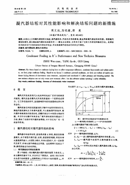
Q = 1 ∞ ( 一h1 1 ∞ ( —k1 0 h )= 0 k )
式中 4l7 ,g g D d , 0 ——凝 汽器的传热量 Jh k/ ;
=
、 — —
() 1
进人 凝汽器 的蒸 汽量和 冷却水量 , h t ; /
h hl c ——凝 汽 器 中 的 蒸 汽 比 焙 和 凝 结 水 比 焓 .
却 水温升 = 一 . 与 l2 之差称为凝汽器的端差 。
0 前
言
凝汽式 汽轮机是 现代火 电站和核 电站广 泛采用的典型 汽轮机。凝汽设备是凝 汽式 汽轮 机装置 的一个重 要组成 部 分 。它工作性 能的好 坏. 直接影 响到汽 轮机装置 的经 济性和 安全性。 凝汽设备在汽轮 机装 置的热力循 环 中起 到冷源的作 用 降低汽轮机 排汽 压 力和排汽 温度 , 以提高循 环热效 率 . 可 凝 汽器冷却表面的污脏或 结垢 . 是凝汽器运 行 中容易 出现 的问 题。本文针 对松 藻矿物局 发 电厂凝 汽器结垢 的 问题 进行 了 分析 . 提出了处理结垢 问题 的新 措施 , 于其它 电厂有一 定 对 的指导作用。
Iwt his I en e c c
ncnnt n em r oo c  ̄c, Ⅱa 0 a o ol c y 0 e nmieet h l ec s
t e u  ̄n
’ s鲫 I i i y sa ea I l bi I
K wod :oxe srfuig;te rm feeto i tr tet u r s  ̄ llne o l n h oe 0 cr ̄ ewae tar t l '  ̄
C n e s rF u ig i t sP r r n ea d Ne e h isMe ¥ll s o d n e o l n I’ ef ma c n w T c n c a l  ̄ n o
燃气轮机进气冷却系统对机组经济性的影响分析
燃气轮机进气冷却系统对机组经济性的影响分析发布时间:2022-05-26T03:16:59.303Z 来源:《福光技术》2022年11期作者:石文昊[导读] 燃气轮机进气冷却系统的工作目的是制冷,降低燃气轮机工作产生的热量,保证燃气轮机始终在合适的温度条件下工作,以提高燃气轮机的使用寿命和运行安全性、稳定性。
随着冷却温度的变化,燃气轮机进气冷却系统的制冷量、投资效益也发生变化。
天津华电南疆热电有限公司天津滨海新区 300450摘要:本文主要介绍燃气轮机进气冷却系统的结构组成、工作原理,从数学角度构建燃气轮机进气冷却系统影响机组经济性的理论模型,并结合案例说明该模型的应用价值。
关键词:进气冷却系统;机组;经济性;数学模型引言:燃气轮机进气冷却系统的工作目的是制冷,降低燃气轮机工作产生的热量,保证燃气轮机始终在合适的温度条件下工作,以提高燃气轮机的使用寿命和运行安全性、稳定性。
随着冷却温度的变化,燃气轮机进气冷却系统的制冷量、投资效益也发生变化。
在实践中,工作人员要结合工作实际需要,综合考虑工作环境露点温度和年投资等因素,合理设计燃气轮机进气冷却系统工作参数和做好事前工作。
1燃气轮机进气冷却系统概述燃气轮机是一种旋转叶轮式的热力发电机,可以助连续流动的气体带动叶轮高速旋转,从而对燃料的能量进行有用做功,将化学能以及其他形式的能量转化为电能。
其工作原理如下:压气机吸入空气,在提高内部空气压力的前提下,同步进行加热,将压缩后的空气送入燃料室,和燃料充分反映后生成高温高压气体。
再讲气体送入透平中,进行膨胀做功,推动压气机高速旋转,将气体和燃料化学能转化为机械能,输出电功。
尽管燃气轮机是一种结构简单、效率高的内燃式动力机械,但仍受限于温度规律影响,导致其使用存在一定局限性。
即燃气轮机的输出随着外部环境温度的升高而逐渐降低。
进气冷却系统是燃气轮机组的重要组成部分,引进进气冷却系统是解决燃气轮机应用温度规律问题的有效手段。
- 1、下载文档前请自行甄别文档内容的完整性,平台不提供额外的编辑、内容补充、找答案等附加服务。
- 2、"仅部分预览"的文档,不可在线预览部分如存在完整性等问题,可反馈申请退款(可完整预览的文档不适用该条件!)。
- 3、如文档侵犯您的权益,请联系客服反馈,我们会尽快为您处理(人工客服工作时间:9:00-18:30)。
q=南="25.38kg/s kJ/(kg·℃);re却水密度p,=996.71kg/m3。 冷却水流量
冷却水流速
,=一=.S/3hi/s
。P-n”孑g- 4d
雷诺数
RK.=,等 :型=:48
35.2148
335 ·
21
R旷>104,处于旺盛紊流区。
则¨1 N./=0.023砖8畴4=264.49
水侧放热系数
一
::
,●
汽轮机技术》 :: 一
::
一
譬
一I
:: 掣
{{{}’
万方数据‘n一Fra bibliotek,'一
·
查表得:A^=0.610W/(m·℃),坳=8.85×10-7m2/s,
2.2.4冷却水管结垢对凝汽器真空、机钮热耗率的影响计算 冷却水管清洁时凝汽器的真空及机组的热耗率 皿=P。一P。=0.09465MPa
P讯=6.06,p,=996.70kg/m’。
此时,冷却水管内径dl=24.2mm,以上述同样的方法可
tX2=缸=6453.56W/(m2·oc)
由牛顿冷却公式Q2=012F(t。一0)得冷却水管壁面温度
气=。+墨=29.77℃
因t。一0=3.82℃<20℃,即冷却水与壁面具有中等以
下温差,所以选用上式计算水侧放热系数正确…。
dl:T—_—雨k:23’ 汽侧放热系数 d-2
780.38W/(m2.儿℃’)
万方数据
106
汽轮机技术
第47卷
空、机组的热耗率。
2凝汽器冷却水管结垢定量分析实例
以某电厂200MW机组凝汽器为例进行说明。
2.1原始计算数据
原始计算数据如表1、表2所示。
表1
凝汽器结构参数
序号
名称
符号 单位
数值
2.2详细计算 2.2.1凝汽器的放热量Q2
由前面所述,Q:=Q。一Q,一Ⅳ Ql=Go(‰一t。)+G_。(Jo—hd)=487 324.96kW Q3可根据设计参数计算选取口3,经计算得Q3= 1.833%Ql,所以,Q2=0.981 67Ql—N=276 859.29kW。 2.2.2凝汽器冷却水管清洁时的计算 传热系数:
和清洗(如本文提到的污垢层可利用机组大小修时间进行酸 洗),以确保凝汽器运行中冷却水管处清洁状态。
(3)凝汽器的运行中,总希望知道冷却水量的大小。而 测量和测准冷却水量是比较困难的,即使采用先进的超声波 流量计,也要在地面下挖出很深的坑,况且冷却水管直径大, 也不易测准。从热力学第一定律出发,不仅定量计算了冷却
万方k.数。据一Q2FAt=。页Q2ij:1_Jtn,■一t“ i
=2 332.90W/(Ill2·℃)
冷却水平均温度t,::毕:25.95。C
●,一
^
一
‘
。
上
以此为定性温度,查表得:
导热系数A,=0.6lOW/(m·℃);动力粘度吩=8.86×
10。7 m2/s;普朗特数P,,=6.07;定压比热容cv/=4.178
要因素是蒸汽的流速、冷却水管的排列、不凝结气体的含量 等。而在汽轮机负荷不变、抽气器工作正常、真空系统严密
3结论
性正常的情况下,上述影响因素是近似不变的…。
凝Q2汽l器:的毛放热 ‰量。:l塑n盟掣:!280785.48kW
因且掣=5.34×10一fj,l—t<w1210-6,说明假定的汽轮 V2I
机排汽温度正确。
(1)上述定量计算表明,冷却水管结垢严重影响着凝汽 器真空及机组运行的经济性。冷却水管结垢0.4mm时,使凝 汽器真空下降2.216kPa,使机组的功率减少3 926.04kW,使 机组的热耗率增加172.951d/(kW·h)。为了更进一步说明 问题,在这里还以同样的方法计算了不同污垢层厚度对凝汽 器真空及机组经济性的影响数据,如表3所示。
式中,P。为汽轮机排汽压力,MPa;△Ⅳ为因排汽压力升高 (凝汽器真空降低)使机组功率的减少值,MW。
现假定冷却水管内壁结了龟=0.4ram厚的水垢,导致排 汽温度由l。=37.2。C上升至t,l=42.695 1℃,则与之对应的
排汽压力由以=0.00635MPa上升至P。1=0.008 566MPa,机 组的功率减少
qo:—36百00一Ql:8705.]3kJ/(kW.h)
计算出:冷却水流速埘,l=1.828m/s,雷诺数R矾=49985.99,
努谢尔特数%=271.52,水侧放热系数屹,=6 844.10
W/(m2·℃)。
则h,2传r热j系五数 “5钇31w/(m2汽)
一十一t—t—
al
屹I
Al
A2
在传热系数七,的计算中,认为冷却水管污染前后凝汽
版社。1993. [2]庞麓鸣,汪孟乐,冯海仙.工程热力学【M].北京:高等教育出
版社,1986. [3]林万超.火力发电厂热力系统节能分析[M].北京:水利电力
出版社,1987. [4]杨世铭.传热学[M].北京:高等教育出版社,1987.
水管结垢对凝汽器真空、机组功率及机组热耗率的影响,还
5
55岛 ::
表3
凝汽器冷却水管结垢有关计算结果汇总
(2)由表3可看出,随污垢层厚度的增加,凝汽器的真空 成功地计算了凝汽器的冷却水量。
和机组的功率近似成正比例下降,机组的热耗率近似成正比 例增大。所以机组运行中,除按规定投用凝汽器胶球清洗装
参考文献
置外,还应根据当地冷却水质情况,对凝汽器进行定期检查 [1】杨善让.汽轮机凝汽设备及运行管理[M].北京:水利电力出
k
Ot2
AI
2.2.3凝汽器冷却水管结垢时的计算
该电厂冷却水系统采用闭式循环,用地下水作为凝汽器
的冷却水。该冷却水的碱度、硬度大,水垢的成份主要是碳 酸钙和碳酸镁,其导热系数A:=1.75W/(in·℃)。
利用计算机程序将凝汽器真空通用曲线拟合成以下公
式
AN=1 771.68p。一9.12 (P。≥0.005 15MPa)
ANl=1 771.68(p。l—P。)=3926.04kW
根据热力学第一定律,此时凝汽器放热量应为 Q20=Q2+△Ⅳl=280 785.33kW
冷却水出水温度
,1
t砬l=·:等+t。l=30.73℃
定性温度
o矿u"
第2期
王运民:定量分析凝汽器冷却水管结垢对机组经济性的影响
107
“:毕:26.02aC
器的汽侧放热系数是不变的。因为影响汽侧放热系数的主
冷却水管结垢0.4mm时凝汽器的真空及机组的热耗率
皿l=P。一见t=0.092434MPa
:2矿等i黑两:2 8 ·
.岫h)
878.08kI/(kWql
冷却水管结垢O.4mm时使凝汽器的真空下降 AH=皿一巩=2.216×10一MPa
冷却水管结垢0.4mm时使机组的热耗率增加 Aq=ql—qo=172.95U/(kW.h)