CAT3500说明书解析
吉泰科3500变频器说明书

吉泰科3500变频器说明书引言吉泰科3500变频器是一种先进的电力控制装置,被广泛应用于工业生产、机械设备以及运输工具等领域。
它的主要功能是通过改变电源频率,调整电机的转速,从而实现对电力输出的控制。
本篇文章将对吉泰科3500变频器的功能、原理和应用进行详细说明。
一、功能介绍吉泰科3500变频器具有多种功能,包括:1. 调速功能:通过改变电源频率,实现对电机的转速调整,从而满足不同工作环境下的需求。
2. 能耗优化:通过精确控制电机转速,减少不必要的能耗,提高能源利用效率。
3. 转矩控制:可以根据负载实时变化的要求,通过调整输出功率,实现对转矩的控制。
4. 保护功能:具备电流、电压、温度等多种保护功能,保证设备的稳定运行和安全性能。
5. 通信功能:支持多种通信协议,实现与其他设备之间的无缝连接与数据共享。
二、工作原理吉泰科3500变频器的核心原理是改变电源的频率,通过变频器内置的电子元件和逻辑电路实现对电机的控制。
具体而言,它包括以下几个关键环节:1. 输入电路:将交流电源转换为直流电源,以供后续电子元件的正常工作。
2. 逆变电路:将直流电能转换为交流电能,具体的频率和电压由后续控制电路决定。
3. 控制电路:根据用户的需求和控制信号,调整输出电流和频率,实现对电机速度的精确控制。
4. 保护电路:监测电流、电压和温度等参数,一旦超过规定范围,及时采取保护措施,防止设备受损。
三、应用领域吉泰科3500变频器广泛应用于各个领域,以下是一些典型应用场景的介绍:1. 工业生产:在工业自动化的领域中,变频器可以实现对生产线上设备的精确控制,提高生产效率和质量,降低能耗。
2. 机械设备:无论是传统的机械设备还是现代的机器人技术,变频器都扮演着重要角色,通过调整转速实现对机械运动的控制。
3. 交通运输:交通运输工具如电动车、列车、船舶等,都需要变频器来控制电机的转速,实现对车速的调节和动力输出的优化。
4. 风能发电:在可再生能源领域,变频器被广泛用于调整风力发电机组的转速,使其始终处于最佳工作状态。
CAT说明书中文

altronic 控制器系统 de-2500型操作说明(型号 de-2500 ioi 09-01)1.1 为了使读者更好地把握本文档的各主题内容,52页提供了说明书的章节目录,从47页开始罗列了文档中使用的技术术语词汇表。
altronic de-2500控制器系统是基于微处理器的电子系统,设计用于自动检测各类模拟和数字输入信号,来控制和监测工业压缩机。
该系统是可以使用pc(个人电脑)和提供的de-2500终端编程器进行现场编程的,并且可以通过固定存储器存储这些设置。
提供了串行通信接口,用于连接pc接口、plc接口、调制解调器和用于远程通信的卫星链路。
背后照明的4 x 20 lcd 字符显示表示了系统的状态、可编程引擎/发动机和压缩机参数和通道标号。
安装在前端的掌上键盘充当用户操作接口。
de-2500 提供了安全关闭功能,以避免对远程操作设备造成不必要的损害;同时提供了闭环自动控制功能,以优化提高系统的运行效率。
另外,de-2500支持远程数据获取并可以通过一个低成本的简单工具包专门对工业压缩机的应用程序进行监督控制。
适合于压缩机生产能力管理的优化策略包括原动力转速自动调整和容量控制。
在旋转式调节压缩机中,容量控制可以通过抽气节流阀或使用提升阀、旋转阀或滑阀的内部气体旁路输送技术实现。
在活塞往复压气机中,可以使用外部气体旁路输送环或压力调节技术控制容量。
系统的输出选项范围很广,包括模拟电流环和数字输出,支持与当今使用的各类实际系统的接口连接。
并且实现了基于原动力功率容量或其它特殊应用约束(比如制冷能力)的自动负载限制。
可以使用终端程序激活auto start选项。
系统包括三个主要组成部分:安装有显示模块(display module)de-2500的面板、电源供给模块(power supply module)691122-1和接线端模块(terminal module)691127-1。
这些组件通过电缆组件(cable assembly)693115-1交互连接在一起。
3500说明书

Revision NC, July 20023500/33 16 CHANNEL RELAY MODULEOPERATION ANDMAINTENANCE MANUALCopyright © 2002 Bently NevadaAll Rights Reserved.The information contained in this document is subject to change without notice.The following are trademarks of Bently Nevada in the United States and other countries: Actionable Information™, Actionable Information to theRight People at The Right Time™, ADRE®, BentlyNevada®, CableLoc™, Data Manager®, DecisionSupport™, DemoNet™, Dynamic Data Manager®,Dynamic Transmitor™, Engineer Assist™,FieldMonitor™, FluidLoc™, FlexiTIM™, FlexiTAM™,Helping you Protect and Manage All Your Machinery®,HydroVU™, Key ∅®, Keyphasor®, Machine ConditionManager™ 2000, MachineLibrary™, MicroPROX®,Move Data, Not People™, Move Information, NotData™, Performance Manager™, PROXPAC®,Proximitor®, REBAM®, Seismoprobe®, System 1™,TDIXconnX™, Tecknowledgy™, TipLoc™,TorXimitor®, Transient Data Manager®,Trendmaster®, TrimLoc™, VAM™, Velomitor®,Xlerometer™Bently Nevada’s orbit logo and other logos associatedwith the trademarks in bold above, are also alltrademarks or registered trademarks of Bently Nevadain the United States and other countries."The following ways of contacting Bently Nevada are provided for those times when you cannot contact your local Bently Nevada representative:Mailing Address 1631 Bently Parkway SouthMinden, NV 89423USATelephone 1 775 782 36111 800 227 5514Fax 1 775 782 9259Internet 3500/33 Operation and MaintenanceAdditional InformationNOTICE:This manual does not contain all the information required to operate andmaintain the 16 Channel Relay Module. Refer to the following manualsfor other required information.3500 Monitoring System Rack Installation and Maintenance Manual (129766-01)• general description of a standard system• instructions for installing and removing the module from a 3500 rack• drawings for all cables used in the 3500 Monitoring System3500 Monitoring System Rack Configuration and Utilities Guide (129777-01)• guidelines for using the 3500 Rack Configuration software for setting the operating parameters of the module• guidelines for using the 3500 test utilities to verify that the input and output terminals on the module are operating properly3500 Monitoring System Computer Hardware and Software Manual (128158-01)• instructions for connecting the rack to 3500 host computer• procedures for verifying communication• procedures for installing software• guidelines for using Data Acquisition / DDE Server and Operator Display Software• procedures and diagrams for setting up network and remote communications3500 Field Wiring Diagram Package (130432-01)• diagrams that show how to hook up a particular transducer• lists of recommended wiringiii3500/33 Operation and Maintenanceiv Contents1Receiving and Handling Instructions (1)1.1Receiving Inspection (1)1.2Handling and Storing Considerations (1)1.3Disposal Statement (1)2General Information (3)2.1The 16 Channel Relay Module (4)2.2Statuses (8)2.3LED Descriptions (10)2.3.116 Channel Relay Module (10)3Configuration Information (11)3.1Hardware Considerations (11)3.2Entering Alarm Drive Logic (11)3.2.1Relay Module Configuration Considerations (12)3.2.2Relay Module Configuration Options (13)3.3Software Switches (16)4Output Module Description (19)4.116 Channel Relay Output Module (19)4.2Wiring Euro Style Connectors (22)5Maintenance (25)5.1Verifying a 3500 Rack - Relay Module (25)5.1.1Choosing a Maintenance Interval (25)5.1.2Required Test Equipment (26)5.1.3Typical Verification test setup (26)5.1.4Using the Rack Configuration Software (28)5.1.5Standard Relay Channels (29)5.1.6If a Channel Fails a Verification Test (30)5.2Performing Firmware Upgrades (31)5.2.116 Channel Relay Firmware Upgrade Procedure (31)6Troubleshooting (33)6.1Self-test (33)6.2LED Fault Conditions (34)6.3System Event List Messages (35)6.4Alarm Event List Messages (44)7Ordering Information (45)7.116 Channel Relay Module (45)8Specifications (47)8.13500/33 16 Channel Relay Module (47)3500/33 Operation and Maintenance 1 Receiving and Handling Instructions 1 Receiving and Handling Instructions1.1 Receiving InspectionVisually inspect the module for obvious shipping damage. If shipping damage isapparent, file a claim with the carrier and submit a copy to Bently Nevada.1.2 Handling and Storing ConsiderationsCircuit boards contain devices that are susceptible to damage when exposed toelectrostatic charges. Damage caused by obvious mishandling of the board willvoid the warranty. To avoid damage, observe the following precautions in theorder given.Application AlertMachinery protectionwill be lost when thismodule is removedfrom the rack.• Do not discharge static electricity onto the circuit board. Avoid tools or procedures that would subject the circuit board to static damage. Somepossible causes include ungrounded soldering irons, nonconductive plastics,and similar materials.• Personnel must be grounded with a suitable grounding strap (such as 3M Velostat No. 2060) before handling or maintaining a printed circuit board.• Transport and store circuit boards in electrically conductive bags or foil.• Use extra caution during dry weather. Relative humidity less than 30% tends to multiply the accumulation of static charges on any surface.• When performed properly, this module may be installed into or removed from the rack while power is applied to the rack. Refer to the Rack Installation andMaintenance Manual (part number 129766-01) for the proper procedure. 1.3 Disposal StatementCustomers and third parties that are in control of product at the end of its life orat the end of its use are solely responsible for proper disposal of product. Noperson, firm, corporation, association or agency that is in control of product shalldispose of it in a manner that is in violation of United States state laws, UnitedStates federal laws, or any applicable international law. Bently Nevada is notresponsible for disposal of product at the end of its life or at the end of its use.13500/33 Operation and Maintenance 23500/33 Operation and Maintenance 2 General Information 2 General InformationThe 16 Channel Relay Module can be used for most monitoring applications. Ituses a single relay to drive the output for each channel. See section 2.1 foradditional information on the 16 Channel Relay Module.1) LEDs indicating the module status.2) LEDs indicating the status of the Relay Channels.3) Terminals for connecting relay contacts to external devices.4) Switches that control how the relay contacts work.32 General Information 3500/33 Operation and Maintenance 2.1 The 16 Channel Relay ModuleThe 16 Channel Relay Module is a full-height module that provides 16 relayoutputs. Any number of 16 Channel Relay Modules can be placed in any of theslots to the right of the Rack Interface Module.Each relay output is fully programmable using AND and OR voting. The AlarmDrive Logic for each relay channel can use alarming inputs (alerts, dangers, Not-OK, and individual channel parameters) from any monitor channel in the rack.This Alarm Drive Logic is programmed using the Rack Configuration Software.The three common types of Alarm Drive Logic configurations are bussed relays,individual relays, and independent relays. Bussed relays use an Alarm DriveLogic that ORs the Alerts or Dangers for all channels in the rack to drive a singlerelay. Individual relays use Alarm Drive Logic that ORs the Alerts or Dangers forchannel pairs (channel 1 and channel 2 or channel 3 and channel 4) in a monitorto drive a single relay. Independent relays use Alarm Drive Logic that causeeach alarm level (Alert and Danger) from a channel to drive a separate relaychannel. The following examples show the drive logic for these three types oflogic.S = Monitor Slot A1 = Alert/Alarm 1C = Channel A2 = Danger/Alarm 243500/33 Operation and Maintenance 2 General Information Bussed Relays (Alert and Danger)##A1 = Any Active Alert ##A2 = Any Active Danger((S02C##A1) OR (S03C##A1) OR ... OR (S15C##A1)) è Trip Relay Channel 1((S02C##A2) OR (S03C##A2) OR … OR (S15C##A2)) è Trip Relay Channel 2Bussed Relays52 General Information 3500/33 Operation and Maintenance6 Individual Relays (Alert and Danger)(S02C01A1) OR (S02C02A1) è Trip Relay Channel 1 (Alert Relay) (S02C01A2) OR (S02C02A2) è Trip Relay Channel 2 (Danger Relay) (S02C03A1) OR (S02C04A1) è Trip Relay Channel 3 (Alert Relay) (S02C03A2) OR (S02C04A2) è Trip Relay Channel 4 (Danger Relay)Individual RelaysIndependent Relays (Alert and Danger)(S02C01A1) è Trip Relay Module in slot 3 Channel 1(S02C02A1) è Trip Relay Module in slot 3 Channel 2(S02C03A1) è Trip Relay Module in slot 3 Channel 3(S02C04A1) è Trip Relay Module in slot 3 Channel 4(S02C01A2) è Trip Relay Module in slot 16 Channel 1(S02C02A2) è Trip Relay Module in slot 16 Channel 2(S02C03A2) è Trip Relay Module in slot 16 Channel 3(S02C04A2) è Trip Relay Module in slot 16 Channel 4Independent relays require that you install two 16 Channel Relay Modules for each monitor module.Independent Relays2.2 StatusesThe 16 Channel Relay Module will return both module and channel statuses.This section describes the available statuses and where they can be found.Module StatusOKThis indicates if the 16 Channel Relay Module is functioning correctly. A notOK status is returned under any of the following conditions:• Hardware Failure in the module• Node Voltage Failure• Configuration Failure• Slot ID FailureIf the Module OK status goes not OK, then the system OK Relay on the RackInterface I/O Module will be driven not OK.Configuration FaultThis indicates if the 16 Channel Relay Module configuration is invalid.BypassThis indicates if any of the channels in the 16 Channel Relay Module hasbeen bypassed. Any of the following conditions can cause the Relay Moduleto be bypassed:• A channel has never been configured• The Relay Module is in configuration mode• A Fatal error was found during self-test• Rack Alarm Inhibit has occurred• A channel has an invalid configuration• Any active channel is bypassedAlarm 1 ActiveThis indicates that one or more of the channels of the 16 Channel RelayModule is in alarm.Channel StatusOKThis indicates that no fault has been detected by the associated 16 ChannelRelay Module channel. If the Channel OK status goes not OK, then thesystem OK Relay on the Rack Interface I/O Module will be driven not OK.BypassThis indicates if the associated 16 Channel Relay Module channel has been bypassed. Any of the following conditions can cause the channel to bebypassed:• The channel has never been configured• The Relay Module is in configuration mode• A Fatal error was found during self-test• Rack Alarm Inhibit has occurred• The channel has an invalid configuration• The channel is bypassed using a software switchChannel OffThis indicates if the associated 16 Channel Relay Module channel has been turned off (not Active). The Relay channels may be turned off (inactivated) using the Rack Configuration Software.Alarm 1 ActiveThis indicates if the associated 16 Channel Relay Module channel is inalarm.The following table shows where the statuses can be found.Statuses Comm.GatewayModuleRackConfigurationSoftwareOperatorDisplaySoftware3500/94VGADisplayModule OK X X X Module ConfigurationFaultXModule Bypass XModule Alert/Alarm 1ActiveX X X Channel OK X X X X Channel Bypass X X X X Channel Off X X X Channel Alert/Alarm 1ActiveX X X2.3 LED DescriptionsThe LEDs on the front panel of the 16 Channel Relay Module indicate theoperating status of the module as shown in the following figures. Refer toSection 6.2 for all of the available LED conditions.2.3.1 16 Channel Relay Module1) OKIndicates that the 16 Channel Relay Module andthe 16 Channel Relay Output Module areoperating correctly.2) TX/RXFlashes at the rate that messages are received.3) Channel AlarmIndicates that an alarm condition has occurredwith this relay.3 Configuration InformationConfigure 3500 relay modules by using the Relay Association screen to enteralarm drive logic for each relay channel and by using the Software Switchesscreen to set software switches. This section defines the options on theseconfiguration screens. The Rack Configuration and Utilities Guide (part number129777-01) shows how to operate those screens.3.1 Hardware ConsiderationsThe Slots in the rack are numbered from 0 to 15, counting from left to right. Thepower supplies go into slot 0 and the Rack Interface module goes into slot 1.Slots 2 through 15 are called “monitoring positions”. The 3500/33 module canbe installed into any of the monitoring positions. However, if the 3500/20 RackInterface Module and Data Manager I/O are to be used to interface to DDIX,TDIX or TDXnet, refer to the manual on the 3500/20 for slot restrictions this mayplace on your configuration.3.2 Entering Alarm Drive LogicUse the Relay Association screen to enter the alarm logic that controls whatalarms cause the channels in the relay to drive the output.Relay Association Screen for a 16 Channel Relay Module3.2.1 Relay Module Configuration Considerations•Add monitor modules to the rack configuration before configuring the Relay Module.• Activate only the Relay Module channels that will be used.• Only monitor modules may be used in the alarm drive logic.• Plan ahead to determine if any channels will be configured as channel pairs (DPDT).• Consider if your application will need True or Normal AND voting logic.• When configuring several channels with similar logic or conditions, consider utilizing the Copy function.• Prior to downloading, the configuration software will determine if the number of instructions exceeds the limit of your relay module. The 16-Channel Relaymodule is limited to 100 logical operations per channel for each of the 16channels.• Prior to exiting the Relay Association screen, the configuration software will determine if there are errors in any channel alarm drive logic. The cursor willbe placed at the location of the syntax error.3.2.2 Relay Module Configuration OptionsAvailable MonitorsA field that shows the monitors in the rack.Rack TypeThe type of Rack Interface Module installed in the rack (Standard or TMR).Config IDA unique six character identifier which is entered when a configuration isdownloaded to the 3500 rack.Relay SlotThe location in the 3500 rack of the relay module being configured.ActiveA check box that applies to the selected channel in the Channel Associationgroup. The relay channel drives the output only when this box is enabled (x)and the alarm drive logic for the channel is true.Latching RelaysWhen this option is selected, the corresponding relay alarm channel will hold thealarm state until it receives a rack reset or the relay is reconfigured.Relay Channel Pair (DPDT)When this option is selected, the current channel will be grouped with its channelpair, thus allowing both channels to have identical configurations and alarmlogic.Standard Relay Channel AssociationA group for selecting the channel, or channel pair, to be configured andactivated.Relay NE/NDE Switch StatusIndicates how the relay hardware switches are set on the Relay Output Module.This status is only available after the relay has been uploaded.Available Monitor Channels/AlarmsWhen a monitor is selected, this area shows all the alarms that are available forthe relay module.Alarm Drive LogicBuild the alarm drive logic in this area using the available monitor alarms. AND Voting SetupThis option allows you to determine the type of AND voting for a standard rack type.AND Voting Setup ScreenNormal AND Voting (Default)With this option selected, if an alarming parameter is Not OK or bypassed (either by user selection or monitor failure), then the parameter will be removed from the relay logic. Please note: A “Not-OK” alarming parameter (a parameter intended to alarm on a Not-OK condition) will not be removed from the alarm logic equation.True AND VotingSelecting True AND logic causes alarming parameters that are Not OK or bypassed to remain in the relay logic. Using 'True And' logic will not drive an alarm if an alarming parameter being And-ed is Not OK (parameters not intended to alarm on a Not-OK condition) or in bypass.Important: Care must be taken when selecting the AND voting to be used; consider the configuration settings for the channel to be used as an alarm parameter. Not OK Channel Defeat (single channel measurements), Not OK Channel Pair Defeat (paired channel measurements), Timed OK Channel Defeat and Latching vs. Non-Latching Not OK modes all affect the circumstances that cause a channel to be "Not OK" or bypassed. The following channel types have special scenarios to consider:Thrust Position: Monitor reports an Alarm (not a "Not OK" condition) to the relay module for a transducer not OK.Overspeed, Zero-Speed, Rotor Speed: These channel types have optional "OK Voltage Checks" that will determine if the monitor will or will not report a Not OK status to the relay module due to a transducer voltage error.Eccentricity: "Direct Channel Above 600 RPM" affects bypass and Not OK status.3.3 Software SwitchesSoftware switches for relay modules let you temporarily bypass or inhibit therelay module and channel functions. Set these switches on the SoftwareSwitches screen under the Utilities Option on the main screen of the RackConfiguration Software. Switch settings take affect only after you press the Setbutton.Configuration ModeA switch that allows the 16 Channel Relay Module to be configured. Toconfigure a relay module, enable (x) this switch and set the key switch on thefront of the Rack Interface Module in the PROGRAM position. Whendownloading a configuration from the Rack Configuration Software, this switchwill automatically be enabled and disabled by the Rack Configuration Software.If the connection to the rack is lost during the configuration process, use thisswitch to remove the module from Configuration Mode.The module switch number is used in the Communication Gateway Module.Module Switch Number Switch Name1 Configuration Mode3500/33 Operation and Maintenance 3 Configuration InformationBypassWhen enabled (x), the channel will be turned off and not allow alarming.The channel switch number is used in the Communication Gateway Module.Channel Switch Number Switch Name1 Bypass3 Configuration Information 3500/33 Operation and Maintenance3500/33 Operation and Maintenance 4 I/O Modules Description 4 Output Module DescriptionThis section describes the Output module that is associated with the 16 ChannelRelay Module. This section also describes how to use the connectors on theRelay Output Module and describes where to install each Output module.4.1 16 Channel Relay Output ModuleThe 16 Channel Relay Output Module contains 16 sets of relay contacts (one foreach channel) and can be setup so each channel (in groups of four channels) isNormally Energized or Normally De-energized. The 16 Channel Relay OutputModule must be installed behind the 16 Channel Relay Module (in a Rack Mountor a Panel Mount rack) or above the 16 Channel Relay Module (in a Bulkheadrack).1) Terminals for connecting tothe single-pole, double-throw(SPDT) relays.2) DIP switches for configuringthe relays for NormallyEnergized (NE) or NormallyDe-energized (NDE). Thenumbers refer to relaychannel groups. Forexample, CH1-4 correspondsto relay channels 1 thru 4.4 I/O Modules Description 3500/33 Operation and MaintenanceConfiguring the Normally Energized and De-Energized Relays1) Screwdriver2) Module Cover3) DIP SwitchCAUTIONProper dipswitch configuration techniquerequires the Output module to be removedfrom the rack. Failure to follow this warningcould expose personnel to dangerously highvoltage levels that could cause shock or burnsand damage to the Output Module.CAUTIONProper Output module installation requirespower to be removed from the rack. Failure tofollow this warning could cause seriousdamage to the Output Module.3500/33 Operation and Maintenance 4 I/O Modules DescriptionNoteRelay contacts are marked NC (Normally Closed), NO (Normally Open), andARM (Armature). NC and NO define the state of the relay contacts with nopower applied to the relay coil (de-energized , non-alarm state).Normally Energized Normally De-energized(NE) (NDE)1) No Power/ No Alarm (shelf state)2) With Power/ No Alarm3) With Power/ In Alarm4 I/O Modules Description 3500/33 Operation and Maintenance 4.2 Wiring Euro Style ConnectorsTo remove a terminal block from its base, loosen the screws attaching theterminal block to the base, grip the block firmly and pull. Do not pull the blockout by its wires because this could loosen or damage the wires or connector.WARNINGHigh voltage may be present on the relay contacts or relay wiring.This voltage could cause shock, burns or death. Use proper isolationtechniques.Remove all power when working with the relays.3500/33 Operation and Maintenance 4 I/O Modules Description Refer to the 3500 Field Wiring Diagram Package for the recommended wiring.Do not remove more than 6 mm (0.25 in) of insulation from the wires.5 Maintenance 3500/33 Operation and Maintenance3500/33 Operation and Maintenance 5 Maintenance 5 MaintenanceThe boards and components inside of 3500 modules cannot be repaired in thefield. Maintaining a 3500 rack consists of testing module channels to verify thatthey are operating correctly. Modules that are not operating correctly should bereplaced with a spare.When performed properly, the main module may be installed into or removedfrom the rack while power is applied to the rack. The relay output module shouldonly be installed or removed when the power to the rack has been removed.Refer to the Rack Installation and Maintenance Manual (part number 129766-01)for the proper procedure.This section shows how to verify the operation of the 3500/33 16 Channel RelayModule.5.1 Verifying a 3500 Rack - Relay ModuleThe 3500 Monitoring System is a high precision instrument that requires nocalibration. The functions of Relay Module channels, however, must be verifiedat regular intervals. At each maintenance interval, we recommend that you usethe procedures in this section to verify the operation of all active channels in theRelay Module.Section Number Topic PageNumber5.1.1 Choosing a Maintenance Interval 255.1.2 Required Test Equipment 265.1.3 Typical Verification Test Setup 265.1.4 Using the Rack Configuration Software 285.1.5 Standard Relay Channels 295.1.1 Choosing a Maintenance IntervalUse the following approach to choose a maintenance interval:• Start with an interval of one year and then shorten the interval if any of the following conditions apply:o Monitored machine is classified as criticalo 3500 rack is operating in a harsh environment such as in extremetemperature, high humidity, or in a corrosive atmosphere • At each interval, use the results of the previous verifications and ISO Procedure 10012-1 1992(E) to adjust the interval.5 Maintenance 3500/33 Operation and Maintenance5.1.2 Required Test EquipmentThe test equipment needed to simulate the inputs for the relay channel willdepend on the type of monitor providing inputs to the Relay Alarm Drive Logic.This equipment can be found under Required Test Equipment in theMaintenance section of the specific monitor manual.5.1.3 Typical Verification test setupThe following figure shows the typical test setup for verifying a Relay Module.The test equipment is used to simulate the transducer signal to selectedmonitors and the laptop computer is used to observe the output from the rack.1) 3500 Rack2) Test Equipment3) RS-232 communications4) Laptop ComputerTransducers can be connected to a 3500 rack in a variety of ways. Dependingon the wiring option for the I/O module of your monitor, connect the testequipment to the Monitor Module and Relay Module using one of the followingmethods:3500/33 Operation and Maintenance 5 Maintenance1) Connect test equipment here.2) Inputs3) Monitor I/O Module (Internal Termination)4) External Termination Block (Euro Style Connectors)5) External Termination Block (Terminal Strip Connectors)5 Maintenance 3500/33 Operation and Maintenance1) Outputs16 Channel Relay Output Module5.1.4 Using the Rack Configuration SoftwareThe laptop computer that is part of the test setup uses the Rack ConfigurationSoftware to display output from the rack and to reset certain operatingparameters in the rack. To perform the test procedures in this section you mustbe familiar with the following features of the Rack Configuration Software.• upload and save configuration files• display the Verification screenThe Rack Configuration and Test Utilities Guide (part number 129777-01)explains how to perform these operations.NoteSave the original rack configuration before doing any maintenanceor troubleshooting procedures.3500/33 Operation and Maintenance 5 Maintenance The Verification screen displays relay channel output from a 3500 rack as shownin the following figure. Information such as Alarm Drive Logic, Channel AlarmState and Channel OK State are used to verify relay channels.5.1.5 Standard Relay ChannelsVerify relay channels by forcing alarms from the monitors that provide inputs forthe Relay Alarm Drive Logic. When the logic is true, the Channel Alarm Statewill change to Alarm on the Verification screen and the alarm relay and frontpanel LED for that channel will change state. Verify only those channels that areactive and configured.To verify that a 16 Channel Relay channel is working correctly.1. Run the Rack Configuration Software on the test computer.2. Choose Verification from the Utilities menu. A screen prompting for theslot and channel number of the relay to be tested will appear.3. Choose the proper Slot number and Channel number and then click on theVerify button. The Verification screen will appear.4. Verify that the Channel OK State status on the Relay Verification screenreads OK.5. Use the Relay Verification screen to determine what inputs must besimulated.6. Simulate the required Alarm Drive Logic inputs to cause the relay to changestates.。
Caterpillar G3500 SI EIS 升级应用和集成指南说明书
Application and Integration Guide UPGRADE FOR CATERPILLAR G3500 SI/EISForm CAT-3500-UPG AIG 8-111.0 SYSTEM DESCRIPTION1.1 The retrofit ignition/control system for Caterpillar G3500 SI/EIS is a simple, pre-engineered solution that allows operators of legacy G3500 engines equipped with SI or EIS ignition systems an upgrade path to industry-standard, cost-effectiveAltronic ignition and control components. This package enables operators of these engines to enjoy greater flexibility in the control of their equipment, and ensures future parts availability and upgrade options through Altronic and it’s globalDistributor network. The key components of this upgrade include the CPU-95ignition, the DET-1600 detonation detection system, and the DSG-1682DUPSdual-setpoint gauge.1.2 The Altronic CPU-95, DC-powered ignition system is a microprocessor-basedcapacitor discharge system designed for application on natural gas fueled engines.The system features crankshaft-triggered timing accuracy and the capability tovary timing electronically by several means, including an external 4-20mA control signal. The system is field-programmable and offers a variety of advanced control methods, primary and spark diagnostics, self-diagnostics, serial communications and engine protection features. The system consists of two main parts: an engine-mounted Ignition Module and a user interface Display Module.1.3 The Altronic DET-1600 Detonation Sensing Monitor is a 32-bit microprocessor-based electronic instrument that detects and eliminates detonation on naturalgas-fueled engines before damage occurs. Industry-standard low cost broadband piezoelectric vibration sensors, mounted on the engine, are used to transform the vibrations caused by detonation into electrical signals which are then evaluated by the DET-1600. The Detonation Sensing Monitor uses the sensors to measure the combustion intensity of each cylinder in a user-configured time window.The detonation signals are filtered by programmable filters and then sent to the microprocessor for further processing and evaluation. This process is repeatedfor every cylinder on a cycle-by-cycle basis. The resulting two reference numbers, one for detonation intensity and the other for the lack of a combustion process, or misfire, are displayed on a LCD display. These reference numbers are usedto control two output switches, typically one for load control and the other forshutdown, and a 4-20mA current loop used to retard ignition timing.1.4 The Altronic DSG-1682DUPS Digital Bargraph Setpoint Gauge is a two-channelelectronic instrument used to measure two variables and to output a 4-20mAsignal proportional to the differential. Although the gauge is intended to measure pressure, temperature, or vibration, virtually any signal in the range of 0-5V, 0.5-4.5V, or 0-20mA can be used. A backlit, 128 x 64 graphic LCD screen displaysnumeric values, engineering units, labels, and the state of the outputs. A front-mount membrane keypad serves as the user interface.2.0 OVERVIEW AND THEORY OF OPERATION2.1 The retrofit ignition and control system for the Caterpillar G3500 SI/EIS equippedengines allows for the G3500 engine to operate with standard Altronic ignition and control equipment, giving the user the ability to adjust engine operating parameters as the application requires. The system monitors key parameters of engineoperation and adjusts the ignition timing according to a multi-point, user-defined map of ignition timing values. These points include:n I gnition Timing vs. Engine Speedn I gnition Timing vs. Air Manifold Pressuren I gnition Timing vs. Engine Detonation2.2 The ignition timing vs. engine speed curve is a piece-wise linear function that isprogrammed into the CPU-95 output module. This function calculates the global ignition timing retard based on the current engine speed. This function forms one-half of the basic, open-loop ignition timing map used in the G3500 retrofit system.2.3 The ignition timing vs. air manifold pressure curve is a linear function that isprogrammed into the CPU-95 and DSG-1682DUPS gauges. For most commonapplications it is assumed that the air manifold pressure is closely tied to theengine power output, making it a good indication of load. This relationship is based on the premise that higher air manifold pressure results in a larger mass of air and fuel in the combustion chamber. This function forms the other half of the basic, open-loop ignition timing map used in the G3500 retrofit system.2.4 The ignition timing vs. engine detonation curve is a linear function that isprogrammed into the DSG-1682DUPS gauge. It is implemented as an offset to the air manifold pressure curve, allowing for varying amounts of detonation-based ignition timing authority, depending on the particular application. The detonation function is essentially a closed-loop feedback from the engine to adjust the ignition timing based on current combustion characteristics. The DET-1600 is capableof taking additional action in the case of engine detonation using onboard output switches—this may include load control and ultimately, shutdown, depending on the needs of the application.3.0 COMPONENTS3.1 CPU-95 Output Module – See forms CPU-95 AL, CPU-95 II, CPU-95 OI, CPU-95 PI, and CPU-95 SI for complete explanation.3.2 CPU-95 Display Module – See forms CPU-95 AL, CPU-95 II, CPU-95 OI-ED, andfor complete explanation.3.3 Ignition to Junction-box Harness – Dual-connector, shielded, liquid-tite wiringharness that connects from the CPU-95 output module to the ignition junctionbox. Length of this harness should be kept to minimum required for on-engineinstallation. See form EZRail II for additional information.3.4 Ignition Junction-box – EZRail-style, sealed and potted ignition junction-box intendedto mount on-engine and route ignition firing events to the appropriate enginecylinders. Good installation practices dictate that the junction box be mounted as close to the CPU-95 output module as possible. This box should be mounted at the fly-wheel end of the G3500 engine. Choose the appropriate number of outputs for your engine configuration. See form EZRail II for additional information.3.5 Ignition Primary Harness – On-engine wiring harness that connects the ignitionjunction box to the ignition coils. This harness is constructed from PLTC-ER-rated cable, making it suitable for use in hazardous areas—provided the applicableelectrical codes are followed. Each engine bank requires one harness; select the harness with the appropriate number of outputs for your application.3.6 Magnetic Pickups – The CPU-95 ignition uses two magnetic pickups to determineposition information used in calculating ignition timing. See forms CPU-95 AL and CPU-95 II for additional documentation.3.7 Cycle Trigger – The CPU-95 ignition uses a cycle trigger system to determineposition information used in calculating ignition timing. See forms CPU-95 AL and CPU-95 II for additional documentation.3.8 Flange Ignition Coil – The flange-style ignition coil is used in conjunction withthe mating Caterpillar flange-coil valve cover to deliver high-voltage ignitionpulses to the sparkplugs. The standard-duration 591018 coil is specified for new installations, but the long-duration 591012 coil can be used when required.3.9 DET-1600 Detonation Detection System – See form DET-1600 IOM for completeexplanation.3.10 #1 Cylinder and “G” Lead Cable – Used to obtain #1 cylinder primary and ignition“G” lead from the ignition junction box as required by the DET-1600. Additional components may be required to route these signals to the DET-1600.3.11 DET-1600 Sensor Harness – On-engine wiring harness that connects theenclosure containing the DET-1600 to the engine detonation sensors. This harness terminates in a standard MS-5015-style 19-pin connector. An appropriate, panel-mount mate to this connector can be included in an enclosure built by AltronicControls or sourced separately. Each engine bank requires one harness; select the harness with the appropriate number of inputs for your application.3.12 DSG-1682DUPS Gauge – See form DSG-1682DUPS II for complete explanation.3.13 Additional OEM Components for EIS – Given the mechanical design of the EISignition system, additional OEM components are required to allow the engine to accept standard ignition coils and secondary systems. Altronic does not provide these components. The simplified list below should be used as reference only.Always consult the appropriate engine documentation to determine the exactconfiguration and quantity required.4.0 Application Example4.1 Ignition Timing vs. Engine Speed – For this example, it is assumed that theappropriate Ignition Timing vs. Engine Speed function has been defined as show in Figure 1.1. From this it can be determined that the most advanced ignition timing value desired is 28° before top dead center (BTDC) – thus 28° BTDC equals 0° of ignition retard (RET). Continuing this process of extrapolating the desired ignition timing vs. engine speed breakpoints it is possible to express the desired ignition timing in terms of °RET. This process generates the graph shown in Figure 1.2.Once the function is expressed in terms of °RET it is possible to program thisbehavior into the CPU-95 using the “RPM Map” function of the terminal program – see Figure 1.3.CAUTION: This section of the manualis intended to explain the method ofconfiguring the various ignition timingcontrols in the Caterpillar G3500retrofit system. The values used in thefollowing application example ARE INNO WAY REPRESENTATIVE OF ACTUALVALUES USED IN A FUNCTIONINGSYSTEM, and are only intended to helpthe reader understand how the systemcomponents interact. Always referto appropriate engine documentationand ensure that only qualifiedpersonnel establish appropriateignition timing values.FIG. 1.34.2 Ignition Timing vs. Air Manifold Pressure – For this example it is assumed that theappropriate Ignition Timing vs. Air Manifold Pressure function has been defined as show in Figure 2.1. The previous example established that the most advanced ignition timing value desired is 28° BTDC. Again, it is required to re-format the desired ignition timing in terms of °RET. As in the previous example, this process generates the graph shown in Figure 2.2.Given the air manifold pressure is measured in engineering units (i.e., PSIA, PSIG, bar) and the CPU-95’s 4-20mA input map is entered in terms of degreed and milliamps it is important to establish the conversion factor from engineering units to mA. Below is a mathematical process for calculating the formula for the engineering units to mA—assuming the standard Altronic 691204-50 pressure transducer is used and the DSG-1682DUPS is configured for that device the following holds true:CONVERSION FACTOR: 20mA – 4mA = 0.32mA50PSIA – 0PSIA PSIA CONVERSION OFFSET:20mA – (0.32 mA× 50PSIA ) = 4mA PSIACONVERSION FORMULA:CONV. FACTOR × ACTUAL PSIA + CONV. OFFSET = OUTPUT mA EXAMPLE:0.32 mA × 4PSIA + 4mA = 5.28mA PSIACAUTION: This section of the manual is intended to explain the method of configuring the various ignition timing controls in the Caterpillar G3500retrofit system. The values used in the following application example ARE IN NO WAY REPRESENTATIVE OF ACTUAL VALUES USED IN A FUNCTIONINGSYSTEM, and are only intended to help the reader understand how the system components interact. Always refer to appropriate engine documentation and ensure that only qualified personnel establish appropriate ignition timing values.For the values of air manifold pressure given in Figure 2.2, the following table showsthe equivalent points converted to work in the mA scale of the CPU-95.mA of current is complete it is possible to program this behavior into the CPU-95 using the “Special Current Loop Retard” function of the CPU-95 terminalprogram – see Figure 2.3.FIG. 2.34.3 Ignition Timing vs. Engine Detonation – The 4-20mA signal from the DET-1600controls ignition timing in the presence of detonation. This system implements the control as an offset value to the air manifold pressure in the DSG-1682DUPS. The relative impact of the DET-1600’s indicated detonation on ignition timing can becontrolled via the scale factor used in the DSG-1682DUPS—the larger the scale of “DETs”, the larger the overall impact on ignition timing will result. For example, if the DET-1600 input is scaled such that the DSG-1682DUPS interprets the input as 0-5 “DETs” the maximum effect of detonation is to offset the air manifold pressure function by 5. For the purposes of example, assume that the detonation input to DSG-1682DUPS is scaled such that it reads 0-5 “DETs”.4.4 Example:Engine Speed = 1350 RPMAir Manifold Pressure = 23PSIADetonation = 1.5 “DETs”Offset Air Manifold Pressure (0AMP) = 23PSIA – 1.5 “DETs” = 21.5 OAMPTiming = 28° BTDC – 0° RET (RPM) – 3.25° RET (OAMP) = 24.75° BTDCAPPLICATION DIAGRAMDET-1600 SENSOR HARNESS DIAGRAMIGNITION PRIMARY HARNESS DIAGRAM。
华为3500交换机(01)入门操作

华为3500交换机(01)入门操作-CAL-FENGHAI-(2020YEAR-YICAI)_JINGBIANQuidway S3500系列以太网交换机操作手册(一)入门操作第1章产品介绍.....................................................................................................................................................1-1产品简介................................................................................................................................................................. 1-1功能特性列表......................................................................................................................................................... 1-2第2章登录以太网交换机.....................................................................................................................................2-1通过Console口搭建配置环境 .............................................................................................................................. 2-1通过Telnet搭建配置环境..................................................................................................................................... 2-3通过微机Telnet到以太网交换机................................................................................................................ 2-3通过以太网交换机Telnet到以太网交换机 ................................................................................................ 2-4通过Modem拨号搭建配置环境 .......................................................................................................................... 2-5用户界面配置......................................................................................................................................................... 2-8用户界面简介................................................................................................................................................ 2-8用户界面配置................................................................................................................................................ 2-9进入用户界面视图........................................................................................................................................ 2-9配置AUX(即Console)口属性 ................................................................................................................ 2-10配置终端属性.............................................................................................................................................. 2-11用户管理...................................................................................................................................................... 2-13 Modem属性配置........................................................................................................................................ 2-16配置重定向功能.......................................................................................................................................... 2-17用户界面显示和调试.................................................................................................................................. 2-18第3章命令行接口.................................................................................................................................................3-1命令行接口............................................................................................................................................................. 3-1命令行视图............................................................................................................................................................. 3-1命令行特性............................................................................................................................................................. 3-6命令行在线帮助............................................................................................................................................ 3-6命令行显示特性............................................................................................................................................ 3-7命令行历史命令............................................................................................................................................ 3-7命令行错误信息............................................................................................................................................ 3-8命令行编辑特性............................................................................................................................................ 3-8产品介绍产品简介随着Internet市场的不断发展,用户对通信的需求已从传统的电话、传真、电报等低速业务逐渐向高速的Internet接入、可视电话、视频点播VOD(Video On Demand)等宽带业务领域延伸,用户对上网速率的需求也越来越高。
卡特3500发电机组操作和保养手册(中文)

操作和保养手册3500发电机组Y A D1-以上(发电机组)Z A D1-以上(发电机组)Z A H1-以上(发电机组)Z A J1-以上(发电机组)Z A P1-以上(发电机组)P B R1-以上(发电机组)P D R1-U P(发电机组)Z A R1-U P(发电机组)C T H1-U P(发动机)1F Z1-以上(发动机)1G Z1-U P(发动机)SCBU7789-09112004 (中文版112004)重要安全信息产品操作、保养和修理中发生的大多数事故,都是由于不遵守基本安全规则或预防措施而引起的。
若能在事故发生前认识到各种潜在危险,事故往往可以避免。
人员必须对潜在的危险保持警惕,其中包括可能影响安全的人为因素。
还必须进行必要的培训,以掌握正确执行各种功能的技能和工具。
对该产品进行不正确的操作、润滑、保养或修理可能引发危险,甚至可能会造成人员伤亡。
在确认已经获得执行此工作的授权并且阅读和了解了操作、润滑、保养和修理信息前,不要操作本产品或者对本产品执行任何润滑、保养或修理工作。
本手册中及产品上均提供有安全预防措施和警告。
如果对这些危险警告不加以注意,可能会导致自身或他人伤亡。
危险情况以“安全警告符号”后跟“危险”、“警告”或“当心”等“警示文字”来标识。
安全警告的“警告”标签如下所示。
此安全警告符号的含义如下:注意!提高警惕!事关您的安全。
该警告下面的信息说明具体危险情况,或以文字书写,或以图形表示。
对于可能造成产品损坏的片面操作,在产品上和本手册中均以“注意”标志表示。
C a t e r p i l l a r 无法预料到可能发生危险的每一种情况。
因此,本手册和产品上的警告并不包罗所有情况。
请务必首先考虑在使用场所操作本产品所适用的所有安全守则和预防措施,包括具体地点的规定以及适用于现场的预防措施,不得超出本手册的范畴使用本产品。
如果采用了并非C a t e r p i l l a r 公司专门推荐的工具、流程、工作方法或操作技术,必须确保该工具、流程、工作方法或操作技术对您自己和他人是安全的。
猫德(Cat)DEO燃料液体柴油液胶说明书
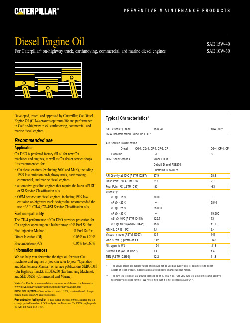
Typical Characteristics*SAE Viscosity Grade15W-4010W-30**EMA Recommended Guideline LRG-1API Service ClassificationDiesel CH-4, CG-4, CF-4, CF-2, CFCG-4, CF-4, CF Gasoline SJ SHOEM SpecificationsMack EO-M Detroit Diesel 7SE270Cummins CES20071API Gravity at 16ºC (ASTM D287)27.9 28.9Flash Point, ºC (ASTM D92)218 210Pour Point, ºC (ASTM D97)-33-33Viscosity:cP @ - 15ºC 3000 –cP @ - 20ºC –2840 cP @ - 25ºC 25,000–cP @ - 30ºC–19,500cSt @ 40ºC (ASTM D445)120.773cSt @ 100ºC (ASTM D445)15.511.0HT/HS, CP @ 15ºC 4.4 3.4Viscosity Index (ASTM D567)134141Zinc % Wt. (Spectro or AA).142.142Nitrogen % Wt. .124.113Sulfate Ash (ASTM D567) 1.4 1.4TBN (ASTM D2896)12.211.8* The values shown are typical values and should not be used as quality control parameters to either accept or reject product. Specifications are subject to change without notice.**The 10W-30 version of Cat DEO is licensed as an API CG-4 oil. Cat DEO 10W-30 utilizes the same additive technology developed for the 15W-40 oil, however it is not licensed as API CH-4.Title Title P R E V E N T I V E M A I N T E N A N C E P R O D U C T SSAE 15W-40SAE 10W-30Developed, tested, and approved by Caterpillar, Cat Diesel Engine Oil (CH-4) ensures optimum life and performance in Cat ®on-highway truck, earthmoving, commercial, and marine diesel engines.Recommended useApplicationCat DEO is preferred factory fill oil for new Catmachines and engines, as well as Cat dealer service shops. It is recommended for:• Cat diesel engines (excluding 3600 and MaK), including 1999 low emission on-highway truck, earthmoving,commercial, and marine diesel engines.• automotive gasoline engines that require the latest API SH or SJ Service Classification oils.• OEM heavy-duty diesel engines, including 1999 low emission on-highway truck designs that recommended the use of API CH-4, CG-4/SJ Service Classification oils.Fuel compatibilityThe CH-4 performance of Cat DEO provides protection for Cat engines operating on a higher range of % Fuel Sulfur:Fuel Injection Method % Fuel Sulfur Direct Injection (DI)0.05% to 1.20%Precombustion (PC)0.05% to 0.60%Information sourcesWe can help you determine the right oil for your Cat machines and engines or you can refer to your “Operation and Maintenance Manual” or service publications SEBU6385(On-Highway Truck), SEBU6250 (Earthmoving Machine),and SEBU6251 (Commercial and Marine).Note:Cat Fluids recommendations are now available on the Internet at: /Products/PartServ/Fluids/FluProd/index.htmDirect fuel injection –if fuel sulfur exceeds 1.20%, shorten the oil change period based on S •O •S analysis results.Precombustion fuel injection –if fuel sulfur exceeds 0.60%, shorten the oil change period based on S •O •S analysis results or use Cat DEO single-grade oil API CF with 13.5 TBN.Diesel Engine Oil For Caterpillar ®on-highway truck, earthmoving, commercial, and marine diesel enginesDiesel Engine Oil••••••••19302000908070605040P E R F O R M A N C E L E V E LYEARCAT Engines and CAT Oil Performance HistorySince its introduction in the late 80’s, the Cat DEO formulation has changed many times to keep pace with new engine technology. You can be assured when you buy Cat DEO that the current formulation exceeds the latest engine oil requirements for Cat Engines.* Engine oil licensed as API CH-4, is automatically approved as API CG-4 and CF-4.Diesel Engine Oil© 2000 Caterpillar。
华为3500路由配置详解
第1章IP路由协议概述说明:当以太网交换机在运行路由协议时,它将同时具备路由器的功能。
在以下路由协议的介绍中所指的路由器及路由器图标,代表了一般意义下的路由器以及运行了路由协议的以太网交换机。
为提高可读性,在手册的描述中将不另行说明。
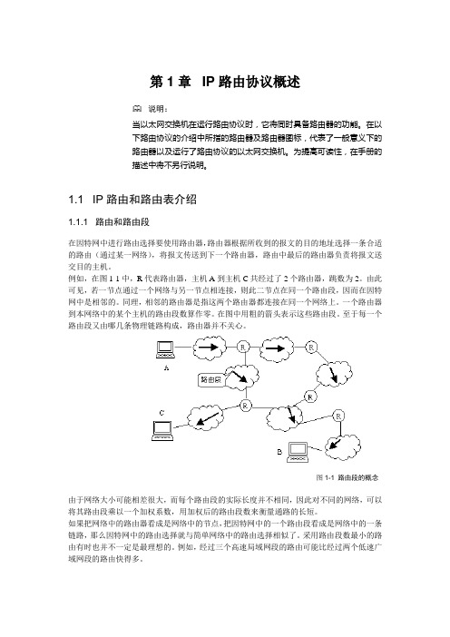
1.1 IP路由和路由表介绍1.1.1 路由和路由段在因特网中进行路由选择要使用路由器,路由器根据所收到的报文的目的地址选择一条合适的路由(通过某一网络),将报文传送到下一个路由器,路由中最后的路由器负责将报文送交目的主机。
例如,在图1-1中,R代表路由器,主机A到主机C共经过了2个路由器,跳数为2。
由此可见,若一节点通过一个网络与另一节点相连接,则此二节点在同一个路由段,因而在因特网中是相邻的。
同理,相邻的路由器是指这两个路由器都连接在同一个网络上。
一个路由器到本网络中的某个主机的路由段数算作零。
在图中用粗的箭头表示这些路由段。
至于每一个路由段又由哪几条物理链路构成,路由器并不关心。
图1-1 路由段的概念由于网络大小可能相差很大,而每个路由段的实际长度并不相同,因此对不同的网络,可以将其路由段乘以一个加权系数,用加权后的路由段数来衡量通路的长短。
如果把网络中的路由器看成是网络中的节点,把因特网中的一个路由段看成是网络中的一条链路,那么因特网中的路由选择就与简单网络中的路由选择相似了。
采用路由段数最小的路由有时也并不一定是最理想的。
例如,经过三个高速局域网段的路由可能比经过两个低速广域网段的路由快得多。
1.1.2 通过路由表进行选路路由器转发分组的关键是路由表。
每个路由器中都保存着一张路由表,表中每条路由项都指明分组到某子网或某主机应通过路由器的哪个物理端口发送,然后就可到达该路径的下一个路由器,或者不再经过别的路由器而传送到直接相连的网络中的目的主机。
路由表中包含了下列关键项:●目的地址:用来标识IP包的目的地址或目的网络。
●网络掩码:与目的地址一起来标识目的主机或路由器所在的网段的地址。
- 1、下载文档前请自行甄别文档内容的完整性,平台不提供额外的编辑、内容补充、找答案等附加服务。
- 2、"仅部分预览"的文档,不可在线预览部分如存在完整性等问题,可反馈申请退款(可完整预览的文档不适用该条件!)。
- 3、如文档侵犯您的权益,请联系客服反馈,我们会尽快为您处理(人工客服工作时间:9:00-18:30)。
3500B和3500系列发动机操作保养手册重要安全信息发动机操作、保养及维修过程中发生的事故大多与未注意阅读基本安全规则或注意事项有关,若能在发生事故前找出潜在危险情况就可避免事故发生。
使用人员应时时注意潜在危险。
要想正确实现发动机的性能,操作人员应拥有一定的技术和工具,并参加必要的培训。
设备操作、润滑、保养或维修不当都是很危险的,且可能会导致人员伤亡。
严禁在未阅读并理解产品操作、润滑、保养和维修说明前进行操作、润滑、保养或维修作业。
手册及产品标牌上标明了安全注意事项和警告;忽视这些危险警告,可能会导致自身或他人伤亡。
本产品用“安全警示符号”来标明存在危险情况,并注有“警示事项”,如“危险”、“警告”或“小心”等语句。
“警告”标签的样签如下:该安全警告表达的意思如下:注意!随时小心,这关系到你的安全。
警告牌会用文字或图案形式标明引起的危险原因。
产品机身及本手册内常采用“注意”标牌注明一些可能会损害产品的操作。
卡特皮勒不可能预测到导致潜在危险发生的每种因素,因此,产品机身上及本手册内列出的警告不能保证万无一失。
在使用一些卡特皮勒不推荐采用的工具、程序、工作方法或操作技术时,必须要考虑到自身及他人的安全,同时还需保证不损伤该产品。
该手册内的资料、规范和图片均以出版该手册时可收集到的资料为基础编写的,这些内容可能会随时更新,有的可能会影响到产品的性能,因此在着手任何工作前,一定要了解到完整且最新资料。
卡特皮勒销售商可提供有关该产品的最新资料,从保养手册目录微缩软片REG1139F上可查到最新版出版号。
警告!卡特皮勒建议使用本厂配件或与本厂配件规格相当的配件,规格相当包括但不仅限于尺寸、型号、强度和材料等面。
忽视该警告可能会导致设备超前失效、产品损坏、人员伤亡。
目录前言 (5)安全部分安全标识 (7)一般危险知识 (11)烫伤预防 (14)防火及防爆 (14)防刮及防碰 (16)安装与拆卸 (16)启动发动机前的准备 (17)发动机启动 (17)发动机停车 (18)电子系统 (18)产品参数部分产品模型 (19)产品铭牌 (24)操作部分发动机的起吊及存放 (29)仪器及仪表 (31)发动机的特点和控制 (35)发动机启动 (88)发动机运转 (97)发动机停车 (99)冬天作业 (103)设备保养章节扭矩参数 (106)润滑油规范 (110)燃料规格 (121)冷却装置规格 (124)供油范围 (139)保养期限 (141)阶段性维修保养计划(备用发电机组发动机) (144)参考信息部分发动机额定参数 (238)客户服务 (242)参考资料 (244)前言说明该手册包括安全、操作说明、润滑和保养要求,应保存在现场资料员手中或资料室。
产品使用人员应掌握该手册内容。
卡特皮勒的出版物大多为英文的,但也有一些译文版本。
本手册中有些图片或说明可能与你所买产品不尽相同,为展示出内部结构,可能拆掉了保护盖。
随产品设计的不断改进,你所用的产品可能会与该手册中内容有不符之处。
不管你对你所购买的产品或该手册有任何疑问,请与产品销售商联系以取得最新资料。
安全该部分列出的是一些最基本的安全注意事项,并标识了一些危险及警告境况,进行操作或对产品润滑、保养和维修前必须阅读并理解该部分所列注意事项。
操作该手册给出的是基本操作技术,它有助于操作人员掌握更好地操作产品所需的技术。
随着操作人员对产品及其性能了解程度的增加,就可提高操作技术。
操作部分供操作人员使用的一份参考资料,用图片形式指导操作人员操作应如何检查、启动、操作和停止发动机,同时也包括电子诊断技术讨论。
保养该部分为发动机保养入门知识,采用图示和分步指令告诉操作人员应判断燃料耗量、服务小时数和保养期限。
保养计划中的诸项与后附详细指令紧密相关。
用耗油量或工作时间来判断期限。
若方便,可用时间间隔(每天、每年等)替代工作期限。
应按保养计划对产品进行保养。
实际作业环境对保养期限有一定影响,在条件恶劣、潮湿、灰尘多或寒冷地区作业时,应缩短保养周期。
保养计划中所列项是为预防性保养管理程序而安排的,若随后进行预防性保养程序,就无需定期调整,预防性保养管理程序的改进可通过减少工作停工和设备失效次数来减少作业成本。
保养期限一定要按要求对产品进行保养,根据保养程度及作业条件调整保养计划。
厂方建议将保养计划复印件保存在作业现场,同时保存保养记录。
参看该手册“保养记录”部分,看哪些保养记录可作为设备保养或修理可接受证据。
销售商可根据作业环境帮你调整你的保养计划。
大修除保养期限和需保养的部件外,该手册未包括大修细节。
大修最好由受过培训人员或经授权的销售商进行。
卡特皮勒销售商会对大修方案提供多种选择。
若你购买的产品出现了大的失效,从销售商处还可得到多种设备失效后大修的方案,请咨询销售商以得到此方面资料。
加利福尼亚提议65警告加利福尼亚州公认柴油机废气和其他一些排放出可导致癌症、胎儿残疾和其他生理疾病。
合格的发动机保养适当的保养和维修对保证发动机的正常运转十分重要。
作为一重型旷野用发动机用户,你应按用户手册和操作保养手册中的要求对设备进行保养。
严禁让非专业人员对产品进行更换配件、修理、操作、销售、租赁或交易。
有些设备元件如排放装置、供油装置、电子装置、空气吸入装置和冷却装置等要用取得卡特皮特许可的更换件。
安全部分安全标识安全管理编号体系号:1000;7405你所用发动机可能的多种安全标志,该部分给出了这些标志的准备位置及内容。
操作人员应了解所有标识。
确保标识清晰,清洗或更换字标或图例不模糊不清的标识。
用布、水和肥皂清洗标识,请勿使用溶剂、汽油或其它刺激性物质,这些物质会降低粘标识粘贴胶的黏着力,从而使标识脱落。
更新已坏或不完好的标识,若标识刚好在需更新部件上,更换后要补贴上新标识。
卡特皮勒销售商可提供备用标识。
警告!未读懂操作保养手册中的说明和警告前,请勿操作或保养该发动机。
不遵循或忽视这些说明和警告可能会导致人员伤亡。
请与卡特皮勒销售商联系,他们可提供这些手册。
保持警提是操作人员的职责。
以下为部分说明了安全标识的位置及内容。
曲柄箱盖曲柄箱盖的警告标识贴在曲柄箱盖上,见箭头所示(图1)。
警告!图1闪火花伤人,在紧急停车后15分钟内打开曲柄箱盖情况下,在未清除停车原因前请勿重新启动。
双燃油滤清器和油料滤清器标识位置见箭头所示(图2)警告!发动机运转时滤清器的油料温度高,且有一定压力。
修理滤清器时应遵循控制阀上标识说明,以免发生人员伤害。
停止发动机以防发生火灾。
配电柜(发电机)标识位置见箭头所示(图3)警告!在发电机与配电装置未断开前,严禁直接在发电机上接多用配电装置,进入配电装置的反馈电压会导致人员伤亡。
断开且锁紧主配电装置开关。
若为永久性接线,安装一双掷开关以防反馈电压。
有些发电机可以在未断开情况下并联配电装置。
在进行操作前请核对你的产品适用情况。
电击标识位于控制面板上,见图4箭头所示。
警告!电击可导致人员伤亡。
不使用时,要断开电器设备电源。
电器包括:发动机控制装置、电子报警器和传感器。
紧急停车紧急停车标识位于控制面板外门上,见图5箭头所示。
警告!通常是在外门开启状态下进行停车,外门关闭时无法接近紧急停车开关,且停车时可能发生人员伤亡。
散热器冷却剂警告标识帖在散热器进液管盖前面,见图6箭头所示。
警告!承压系统:热冷却剂会导致严重烫伤。
先停车,等散热器不热时再开盖。
慢慢松开盖子以释放压力。
底座吊升警告标识贴在底座上,见图7。
警告!起吊操作不当可导致被起吊物翻倒,甚至引起伤亡。
操作人员在起吊前应认真阅读该手册中“起吊发动机”部分内容。
使用不当起吊设备起吊发动机也会发生伤亡事故。
选用强度合适的绳套,起吊时要使用撑杆,并按警告标志中要求系绳套。
高电压高电压警告标识贴在水套加热器上,见图8。
警告!高电压!作业前先切断电源。
带电作业易发生伤亡事故。
发动机吊升警告标志贴在阀盖上,见图9。
警告!起吊操作不当可导致被起吊物翻倒,甚至引起伤亡。
操作人员在起吊前应认真阅读该手册中“起吊发动机”部分内容。
使用不当起吊设备起吊发动机也会发生伤亡事故。
选用强度合适的绳套,起吊时要使用撑杆,并按警告标志中要求系绳套。
警告标志贴在控制面板外门上见图10。
警告!严禁在未阅读并了解该手册前操作或使用发动机或发电机。
不遵守这些警告和指令会导致伤亡事故。
销售商可提供备用手册。
注意安全是你的职责。
预供油泵警告标志贴在预供油泵上,见图11。
警告!电机必须由专人按国家电路规定及当地规定接地线,以防电击。
起吊操作应遵守电机吊升规定。
电机上设有一自动复位温度保护仪,温度过高,温度保护仪会断开电机电路。
电机温度降低后,温度保护会自动复位,并启动电机。
断开电机及附助设备电源后再保养电机,保证电机处于完全静止状态。
燃油喷咀警告标志分别贴在电子控制模块和阀盖上,见图12。
小心电击!使用电压为90-120V.电子控制模块为燃油喷咀一高压信号,切断燃油喷咀连接线。
发动机运转时不要摸燃油喷咀电路连线。
一般危险知识安全管理编号系统编号:1000;7405保养或修理前在发动机启动开关或控制器上挂一“请勿操作”标志牌(如图13所示)。
销售商有此类标志牌。
发动机及每个操作控制台上都要挂该警告牌,可能的话,断开启动控制器。
图13保养发动机时,禁止非专业人员在柴油机附近逗留。
发动机废气中含有对人体有害的易燃物。
发动机通常在通风好的环境中使用。
若在封闭区域内使用,应将发动机废气排放出去。
小心拆下以下部件:●喷咀盖●黄油咀●测压咀●通气孔●排泄塞为防止载压液体溅出,拆以上元件时在上面垫一抹布。
拆封盖时要小心,卸封盖或设备另一端的最后两个螺栓或螺母时先松一下,但不要卸掉,然后将松动的封盖措开一点,以释放压力,之后再拆开螺栓或螺母。
●必要时,戴安全帽、防护眼镜和其它防护用品。
●在发动机附近工作要戴护耳。
●不要穿戴肥大衣服或手饰。
●确保发动机所有护照和封盖固定到位。
●严禁用玻璃器皿装保养液,玻璃器皿易碎。
●小心使用所有清洁用溶液。
●报告所有需修理部位。
除非另有说明,在下述情况才能进行设备保养:●发动机已停;保证无人去启动。
●断开电瓶,并将电瓶地线头用绝缘胶带包好,以防产生火花。
●不要修理搞不懂的设备;使用的工具要合适;更换已坏部件,或修理出故障设备。
载压空气或水载压空气和/或水可致使碎物出现,也可能喷出,以上情形都会引起人员伤亡事故发生。
使用载压空气进行清洗时,要穿戴防护面罩、防护服和劳保鞋。
清洗用空气的最大压力不能超过205kPa (30psi),水不能超过275kPa(40psi)。
清洗冷却装置时通常要戴防护眼镜。
流体穿刺检查发动机部件滴漏时要持一挡板。
漏出的载压液体会严重伤人甚至死亡,包括针孔大小的孔漏失。
若流体刺入皮肤后要立即治疗,且要找专业医生。