KentIntrol调节阀说明书
A-T Controls DR Series 自动球式阀门说明说明书
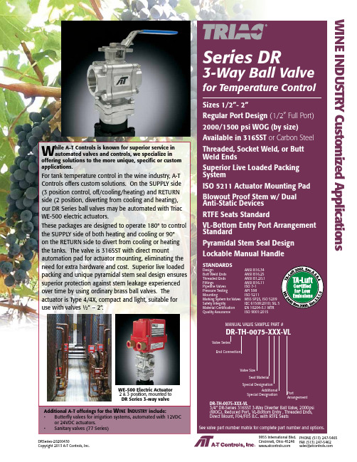
W hile A-T Controls is known for superior service in automated valves and controls, we specialize in offering solutions to the more unique, specific or custom applications.For tank temperature control in the wine industry, A-T Controls offers custom solutions. On the SUPPLY side (3 position control, off/cooling/heating) and RETURN side (2 position, diverting from cooling and heating), our DR Series ball valves may be automated with Triac WE-500 electric actuators.These packages are designed to operate 180° to control the SUPPLY side of both heating and cooling or 90°on the RETURN side to divert from cooling or heating the tanks. The valve is 316SST with direct mount automation pad for actuator mounting, eliminating the need for extra hardware and cost. Superior live loaded packing and unique pyramidal stem seal design ensures superior protection against stem leakage experienced over time by using ordinary brass ball valves. The actuator is Type 4/4X, compact and light, suitable for use with valves ½” – 2”. Series DR3-Way Ball Valve for Temperature Control Sizes 1/2”- 2”Regular Port Design2000/1500 psi WOG (by size) Available in 316SST or Carbon Steel Threaded, Socket Weld, or Butt Weld EndsSuperior Live Loaded Packing SystemISO 5211 Actuator Mounting Pad Blowout Proof Stem w/ DualAnti-Static DevicesRTFE Seats StandardVL-Bottom Entry Port Arrangement StandardPyramidal Stem Seal Design Lockable Manual Handle STANDARDSDesign ANSI B16.34Butt Weld Ends ANSI B16.25Threaded Ends ANSI B1.20.1Fittings ANSI B16.11Pipeline Valves ISO 7-1Pressure Testing API 598Mounting ISO 5211Marking System for Valves MSS SP25, ISO 5209Safety Integrity IEC 61508:2010; SIL 3Material Certification EN 10204-3.1 MTRQuality Assurance ISO 9001:2015Additional A-T offerings for the• Butterfly valves for irrigation systems, automated with 12VDC or 24VDC actuators.• Sanitary valves (77 Series)MANUAL VALVE SAMPLE PART # DR-TH-0075-XXX-VLWE-500 Electric ActuatorDRSeries-20200430Copyright 2013 A-T Controls, Inc.9955 International Blvd.Cincinnati, Ohio PHONE (513) 247-5465FAX (513) 247-5462********************DIMENSIONS (IN)3-Way Diverter Ball Valve for Temperature Control ISO 5211 Direct MountP R E S S U R E I N P S I G2000600400800DRSeries-20200430Copyright 2013 A-T Controls, Inc.SERIES DR 3-Way Diverter Ball ValveSee valve part number matrix for complete part number and options.NOTE: Heater and thermostat standard (2) auxiliary switches standardOther options available - call for detailsActuators are sized based on clean/clear fluid.WE Series Electric Actuator Weatherproof, Type 4, 4XCincinnati, Ohio PHONE (513) 247-5465FAX (513) 247-5462********************ELECTRIC ASSEMBLY SAMPLE PART #Valve SeriesValve SizeSeat MaterialEnd ConnectionTRIAC ActuatorSeriesVoltage AccessoriesDR-TX-075/WEA1-XX-PPositionControl DesignationManual and automated valve assemblies for gas burner management applicationsand safety shutoffVarious Seat MaterialsPTF E, RTF E, 50/50 STF E, 25% CTF E, Delrin,PEEK, UHMWPE, TFM-1600Operator OptionsQuarter-turn Gear OperatorsSpring Return “Deadman” HandlesOval handles, TEE HandlesSpecials and SolutionsSteam JacketsStem ExtensionsV-ported Control ValvesMulti-port Valve SolutionsFugitive Emissions Bonnets (TSM’s)Oxygen CleaningLockout BracketsVented Balls“No Play” Mounting Kits• FM ApprovedValves and AssembliesSpecial SeatsBalls and Seal DesignsFloor MountedDamper DrivesFusible LinkAssembliesLockoutMounting KitsSpecialMulti-Port ValvesSteam JacketedValvesLimit SwitchesMounted on Manual Valves180º ActuatorsStem ExtensionsDual ValveAssembliesCincinnati, Ohio 45246FAX (513) 247-5462********************。
肯特阀门说明书

肯特阀门说明书一、产品概述肯特阀门是一种常见的工业阀门,主要用于控制介质的流量和压力。
它由阀体、阀瓣、阀杆、密封圈等部件组成,具有结构简单、操作方便、密封可靠等特点。
二、产品特点1. 结构简单:肯特阀门采用直通式结构,流道畅通,流体阻力小。
2. 操作方便:肯特阀门采用手动操作方式,旋转角度大,开关灵活。
3. 密封可靠:肯特阀门采用双向密封设计,密封性能好,不易泄漏。
4. 耐腐蚀:肯特阀门主要材料为不锈钢和铜合金等耐腐蚀材料。
三、使用方法1. 安装:在安装前应检查肯特阀门的外观是否完好无损,并清洗内部杂质。
根据管道布局和介质流向确定安装位置,并确保与管道连接牢固。
2. 操作:手动旋转肯特阀门的手柄即可实现开关操作。
注意不要过度旋转或用力过猛,以免损坏零部件。
3. 维护:定期检查肯特阀门的密封性能和操作情况,如发现问题及时维修或更换零部件。
四、注意事项1. 在使用肯特阀门时,应根据介质的性质和流量选择合适的规格和型号。
2. 在操作肯特阀门时,应注意力度适当,不要过度旋转或用力过猛。
3. 在长期未使用肯特阀门时,应定期进行维护保养,以确保其正常运行。
五、常见故障及处理方法1. 泄漏:可能是密封圈老化或损坏导致的。
此时需要更换密封圈。
2. 卡死:可能是阀杆损坏或堵塞导致的。
此时需要清洗或更换阀杆。
3. 无法开关:可能是手柄松动或零部件损坏导致的。
此时需要紧固手柄或更换零部件。
六、结语以上就是肯特阀门的详细说明书,希望对大家有所帮助。
在使用肯特阀门时,请务必严格按照说明书操作,并注意安全事项。
如有任何疑问,请咨询专业人士。
2英寸调节阀操作与维护手册说明书

TECH-SEAL INTERNATIONAL3131 West Little York Rd Houston, Texas 77091Phone: 713-691-0668Fax: 713-358-9330Adjustable Choke Operation and Maintenance ManualRevision: 0Date: 6/06/2013Approved By: J.ATABLE OF CONTENTS1.Introduction ……………………………………………………………………….page 32.Choke Specifications & Features………………………………………………….page 43.Choke Operation…………………………………………………………..………page 54.Exploded View…………………………………………………………………….page 65.Maintenance……………………………………………………………………….page 106.Contact information……………………………………………………………….page 18INTRODUCTION:The 2” Adjustable Chokes is field-proven design which have been manufactured by Tech-Seal International from the high quality material. Tech-Seal Chokes conform to current API requirements, both functionally and in term of calculated stresses. Adjustable Choke is used to control flow rate; it is an important part of a manifold controlling downstream pressure and flow rates during flow-back process.2” 1502 ADJUSTABLE CHOKE SPECIFICATION & FEATURES:Specifications:∙2” 1502 Female Inlet x 2” 1502 Male Outlet∙10,000 psig CWP/ 15,000 psig CWP∙¾” max Orifice and 1.00” max Orifice∙¾” FL/TC and 1.00” FL/TC Seats∙Solid carbide TipFeatures:∙Low Maintenance∙Easy to read position indicator∙Thumb Screw for locking steam∙Available as 2 types: Adjustable Choke and Positive Choke∙Forged steel bodies∙Available H2S service (NACE MR-01-75)∙Choice of orifice sizes∙Easy to convert orifice sizes in fieldCHOKE OPERATION:The 2” 1502 Adjustable Choke features the needle and seat design to allow controllingpressures and flow rate. The choke is operated by turning the hand wheel in CW or CCW in order to obtain a specified downstream pressure, or a desired flow rate.When the desired flow rate or specified pressured is achieved, the thumb screw will beused to locked the stem in fixed position.The choke comes with a position indicator. It is used to determine the bean size needed for the positive choke. Every number on the position indicator represents the equivalent orifice diameter in 1/64th of an inch.NOTE:THIS ADJUSTABLE CHOKE IS NOT DESIGNED TO PROVIDE A POSITIVE SEAL.THEREFORE, AN ISOLATION VALVE SHOULD BE USED IN CONJUNTION WITH THE CHOKE.EXPLODED VIEWS & PART LISTTHE THREE MAIN ASSEMBLIES OF THE CHOKE:Bonnet AssemblyChoke Tee BodyChoke Saver Assembly2” 1502 POSITIVE CHOKE∙EXPLODED VIEW:1 Wing Nut 4 Union Seal 2” 1502 7 Choke saver2 Retainer Ring 5 Body3 Blanking Cap 6 Split Ring∙REPLACEMENT PART & PART NUMBER2” 1502 ADJUSTABLE CHOKE EXPLODED VIEW:REPLACEMENT PART & PART NUMBER`MAINTENANCEWARNING:Tech-Seal Int’l cannot anticipate all of situations a user may encounter while installing, using or repairing products. Therefore, the user must know and follow all applicable industry specifications on the safe installation and use.Failure to follow these warning and instructions could result in serious injury or death!Disassembly:NOTE: Protecting all the sealing surfaces all the time during disassembly or installation process1.Secure the choke assembly on a stationary safe surface.2.Bleed off any internal pressure from the choke assembly3.Loosen the thumb screw and back up the stem away from the seat by turning thehandle CCW.4.Loosen the hammer nut and remove the bonnet assembly.5. Using a choke wrench to remove the seat from the choke tee body6.Remove thumb screw (10), hex nut (1), indicator (4), washer and hand wheel fromthe stem.7.Remove the wing nut(3) from the bonnet assembly8.Unscrew and remove the stem(15) from the bonnet assembly9.Unscrew two socket cap screws and remove the bonnet cap.ing an adjustable wrench to remove the drive bushing (6).11. Remove the snap ring (14) from the bonnet seal pocket.12.Remove stem guide (13), packing retainer (12) and packing set (11) from the sealpocket.13.Unscrew the wing nut to remove the choke saver (21) from the choke tee body(18).INSPECTION-Clean all components-Visual inspection for corrosion, erosion, or any sign of fatigue crack.-Check the shoulder radius of the male end connection for any sign of fatigue crack or corrosion damage.-Check minimum wall at the end connections (see the next page)-Inspect stem carbide tip, and replace as necessary.-Inspect stem sealing surface, and replace as necessary-Inspect stem external thread, and replace as necessary-Inspect seal pocket surface of the bonnet housing for any sign of wear and damage-Check the external thread and carbide surface of the seat for any sign of damage.NOTE:Tech-Seal Int’l highly recommended any dimensions found to be at or thinner the minimum wall thickness requirements, the part or component must be repaired or replaced. Do not use worn, eroded, corrode products.21TSI Flow Products, Inc. Corporate Office CLEBURNE, TX5656 Wheatley St.1717 Hines Rd. Houston, TX 77091 Cleburne, TX 76031 Phone: (713) 691‐0668 Toll Free: 888.593.9143 Fax: (713) 691‐2328 Phone: 817.773.2536Hours: Monday ‐Friday, 8AM ‐5PM CST. Fax: 817.506.7697 CORPUS CHRISTI, TX BRIDGEVILLE, PA 4517 Baldwin 580 Mayer St.Corpus Christi, TX 78408 Bridgeville, Pa. 15017 Toll Free: 877.886.0202 Phone 412‐257‐0100 Phone: 361.882.0202 Fax: 412‐980‐3722Fax: 361.882.0205 .rchurilla@tsi ‐ KILGORE, TXTOWANDA, PA 302 S. longview St. Rr#6 box 6019‐9 Kilgore, TX 75662 Reeves business park Toll Free: 877.984.2870 Towanda pa 18848 Phone: 903.984.2870 570 297 2300Fax: 903.983.3750bpond@tsi ‐。
自力式压力调节阀使用说明书(已配图)

流量特性
快开
调节精度(%)
+-5
使用温度(℃)
≤350
允许 硬密封(L/h)
单座:≤10-4阀额定容量(Ⅳ级) 双座、套筒:≤5x10⁻³阀额定容量(Ⅱ级)
泄漏量软密封(mL/min)0.15 0.30 0.45 0.60 0.90 1.7 4.0 6.75 11.10 16.60
最大
10
减压比
最小
阀后压低于125应提高阀前压力1更换弹簧2重新拆装3重新调整4重新研磨或更换5更换较小口径阀后压力升不上去始终在需求值下方变动阀前压力升不上去始终在需求值下方动作9阀前压力降不下去始终在需求值上方动作阀后压力或阀前压力波动过于频繁1设定弹簧刚度太大2阀口径太小3阀芯阀杆推杆等卡死1阀口径过大2执行机构膜室容量太小1更换弹簧2更换较大口径3排除卡死原因重新调整1选择适当的阀口径2在进液管道内增设阻尼器五订货须知订货时请用户提供以下资料型号公称通径信号范围介质参数额定流量系数阀前最大压力阀前最小压力阀前正常压力最大流量最小流量正常流量材质
(6)阀前应设置过滤器以防止介质中杂质堵塞。 (7)调压阀应安装在环境温度不超过-25℃~55℃的 场合。
2、使用 在常温下使用气体或低粘度液体场合时的操作程序;
(参见图三)
(1)缓慢开启阀前后截止阀。 (2)拧松排气塞,直至气体或液体从执行机构溢出
为止。
8
(3)然后重新拧紧排气塞,调压阀即可工作。所需压 力值的大小可通过压力调节盘的调整而得到,调整时,注 意观察压力表示值,动作应缓慢,不得使阀杆跟着转动。
3、维修 调节阀投入运行后,一般维护工作量很小,平时要观 察阀前、阀后压力表示值是否符合工艺所需值要求即可,
另外,观察填料函与执行机构是否渗漏,若渗漏应拧紧或 更换填料及膜片。调压阀常见故障排除方法(见表五)。
AT Controls 手动和自动旋转阀门文档说明书
9955 International Blvd. • Cincinnati, Ohio 45246 Phone: 513.247.5465 Fax: 513.247.5462Engineer: AMZ No.: DI00043Date Created: 07/09/2019 Date Modified: TSM ExtensionsTSM’s are designed for use with fugitive emissions to act as another form of packing on valve series that are already designed for fugitive emissions. When used manually the handles are lockable. TSM’s also allow for an extended mounting pad to which an actuator can be directly mounted. They can be added to the 22, 24, 33, 55, 77, T77, H78, 8R, 88, 90, D9 and F91 Series. See dimensional drawings P02774, P02776, T11580, and P02997 below.Spring Return HandlesSpring return handles are designed for manual operation and can spring open or close. Depending on the set up the valve will either spring open or closed when the handle is released. They are made up of a triangle pad and a handle. The spring is contained in the handle and is attached to the triangle pad, which can be seen in P03000 along with dimensions and applicable sizes. They can be added to the 22, 33, 77, 88/F88, F91, D9, FD9, 8R, F8R, 83/F83, and 90/F90 series. The F91, 8R / F8R, 83/F83 and 90/F90 series will additionally require a TSM for mounting purposes.Manual Valve with Limit SwitchLimit switches can be mounted to a manual valve using a coupler and a “C” shaped bracket.MATERIALDATECHECKED BY DESCRIPTION9955 INTERNATIONAL BLVD.CINCINNATI, OHIO 45246PHONE: (513) 247-5465FAX: (513) 247-5462DRAWN BY DATEAMZSpring Return Handle Dimensional Drawing07/09/19DO NOT SCALE DRAWINGRELEASED BY CMB07/09/19DATECMB07/09/19VALVES, ACTUATORS, AND AUTOMATION CONTROLS。
热水、冷水调节阀说明书

Close-off pressures are variable and actuator dependent, consult Select Pro and/or Price Guide for specifics.ApplicationThese valves are designed to meet the needs of HVAC and commercial applications requiring bubble tight shut-off for liquids. Typical applications include chiller isolation, cooling tower isolation, change-over systems, large air handler coil control, bypass and process control applications. The large Cv values provide for an economical control valve solution for larger flow applications. Designed for use in Victaulic® piping systems.Jobsite NoteValve assembly should be stored in a weather protected area prior toinstallation. Reference the butterfly valve installation instruction for additional information.2*AFAB C DEF17.0” [433]3.8” [97]16.4” [416]14.3” [363]2.0” [51]Safety NotesWARNING: For Belimo products sold in California: these products do or may contain chemicals which are known to the State of California to cause cancer and or birth defects or other reproductive harms. For more information see .F665VIC Technical Data SheetPressure Enhanced Rubber SeatD a t e c r e a t e d , 09/11/2019 - S u b j e c t t o c h a n g e . © B e l i m o A i r c o n t r o l s (U S A ), I n c .AFAB C DEF10.5” [267]3.8” [97]12.3” [312]10.2” [260]2.0” [51]GRAB C D EF10.8” [275]3.8” [97]10.2” [260]8.1” [206]2.0” [51]Dimensions (Inches [mm])AMA B C DEF9.8” [249]3.8” [97]12.3” [312]10.2” [260]2.0” [51]Dimensions (Inches [mm])GR N4AB C DEF14.1” [358]3.8” [97]13.6” [345]11.5” [292]2.0” [51]F665VIC Technical Data SheetPressure Enhanced Rubber SeatD a t e c r e a t e d , 09/11/2019 - S u b j e c t t o c h a n g e . © B e l i m o A i r c o n t r o l s (U S A ), I n c .GMA B C DEF9.9” [251]3.8” [97]12.3” [312]10.2” [260]2.0” [51]F665VIC Technical Data SheetPressure Enhanced Rubber SeatD a t e c r e a t e d , 09/11/2019 - S u b j e c t t o c h a n g e . © B e l i m o A i r c o n t r o l s (U S A ), I n c .†Rated Impulse Voltage 4kV, Type of Action 1.AA.B, Control Pollution Degree 3.Safety NotesWARNING: For Belimo products sold in California: these products do or may contain chemicals which are known to the State of California to cause cancer and or birth defects or other reproductive harms. For more information see .AFBUP-S-X1 Technical Data SheetOn/Off, Spring Return, AC/DC 24 VD a t e c r e a t e d , 09/11/2019 - S u b j e c t t o c h a n g e . © B e l i m o A i r c o n t r o l s (U S A ), I n c .Wiring Diagrams!WARNING! LIVE ELECTRICAL COMPONENTS!During installation, testing, servicing and troubleshooting of this product, it may be necessary to work with live electrical components. Have a qualified licensed electrician or other individual who has been properly trained in handling live electrical components perform these tasks. Failure to follow all electrical safety precautions when exposed tolive electrical components could result in death or serious injury.Meets cULus requirements without the need of an electrical ground connection.AActuators with appliance cables are numbered.UP Universal Power Supply (UP) models can be supplied with 24 VAC up to240 VAC, or 24 VDC up to 125 VDC.Apply only AC line voltage or only UL-Class 2 voltage to the terminals of auxiliary switches. Mixed or combined operation of line voltage/safetyextra low voltage is not allowed.Provide overload protection and disconnect as required.Actuators may also be powered by 24 VDC.Two built-in auxiliary switches (2x SPDT), for end position indication, interlock control, fan startup, etc.45Actuators may be powered in parallel. Power consumption must be observed.48Parallel wiring required for piggy-back applications.AFBUP-S-X1 Technical Data SheetOn/Off, Spring Return, AC/DC 24 VD a t e c r e a t e d , 09/11/2019 - S u b j e c t t o c h a n g e . © B e l i m o A i r c o n t r o l s (U S A ), I n c .。
AT Controls FD9-F6 Series 600# 直接装配分体流量阀门说明书

Cincinnati, Ohio FAX (513) 247-5462********************FD9-F6Series(B16.34)-20210708Copyright 2013 A-T Controls, Inc.ElectricPneumaticSERIES FD9-F6 600# Direct Mount Split Body Flanged Ball Valve FiresafeSee automated data sheets for pre-sized assembliesEasy to Automate!Triac FD9 Series Flanged Ball Valves feature a direct mount automation pad. The high quality investment castings feature a fully machined bore. The superior live-loaded packing system is accomplished with Belleville washers, “V” ring packing and a unique primary pyramidal stem seal. This advanced sealing system provides protection against stem leaks experienced by ordinary ball valves.available for seat materials. The 50/50 STFE seat option is excellent for services that call for higher temperatures and more difficult applications, including steam. Call us for details.C E R T I F I E D1Additional Special DesignationFD9C-F6-0200-CXXSee part number matrix for itemized optionsHOW TO ORDER MANUAL VALVESSAMPLE PART #Valve SeriesFiresafe End ConnectionCarbon SteelSeat MaterialValve SizeSpecial Designation Graphite Packing*FOR 1/2”-1-1/2” : 4 PCS. OF BOLTS AND NUTS *FOR 2” : 8 PCS. OF BOLTS AND BOLT NUTS $ FOR 1/2” - 1-1/2” : GRAPHITE$ FOR 2” - PTFE: TFM™-1600 GRAPHITE$$ ONLY PRESENT IN 2” DESIGNDIMENSIONS (IN)High Performance, Full Port600# Split Body Flanged Ball Valve Series FD9-F6 (ANSI Class 600)2FD9-F6Series(B16.34)-20210708 | Copyright 2013 A-T Controls, Inc. | | (513) 247-5465API 607 - 6th EditionC E R T I F I ED F I RE S AF EHigh Performance, Full Port600# Split Body Flanged Ball Valve2004006008001000120014001600-100-50050100150200250300350400450500550600P r e s s u r e (p s i )(°F)CTFE STFEPTFETFM-16003FD9-F6Series(B16.34)-20210708 | Copyright 2013 A-T Controls, Inc. | | (513) 247-5465600# FlangedFiresafe Tested to API-607Direct MountSERIES FD9-F6 600# Flanged Direct Mount FiresafeOther options available - call for detailsActuators are sized based on clean/clear fluid.API 607 - 6th EditionC E R T I F I E DSAMPLE PART #Valve SeriesValve Size Seat MaterialEnd ConnectionTRIAC Actuator SeriesActuator Size Double ActingSolenoidLimit SwitchFiresafe See valve part number matrix for complete part number and options.FD9-6C-100/2R3D-XXDIMENSIONS SHOWN ARE FOR ASSEMBLIES SIZED FOR 80 PSI SUPPLY4FD9-F6Series(B16.34)-20210708 | Copyright 2013 A-T Controls, Inc. | | (513) 247-5465DIMENSIONS (IN)Actuators are sized based on clean/clear fluid.DIMENSIONS SHOWN ARE FOR ASSEMBLIES SIZED FOR 80 PSI SUPPLYSAMPLE PART #Valve SeriesValve Size Seat MaterialEnd ConnectionTRIAC Actuator SeriesActuator Size Spring ReturnSolenoidLimit SwitchFiresafe See valve part number matrix for complete part number and options.FD9-6C-100/2R3S-XXSERIES FD9-F6 600# Flanged Direct Mount Firesafe600# FlangedFiresafe Tested to API-607Direct MountAPI 607 - 6th EditionC E R T I F I E D5FD9-F6Series(B16.34)-20210708 | Copyright 2013 A-T Controls, Inc. | | (513) 247-5465600# FlangedFiresafe Tested to API-607Direct MountSERIES FD9-F6 600# Flanged Direct Mount FiresafeOther options available - call for detailsActuators are sized based on clean/clear fluid.API 607 - 6th EditionC E R T I F I E DSAMPLE PART #Valve SeriesValve SizeSeat MaterialEnd ConnectionTRIAC Actuator SeriesActuator SizeOn-OffVoltageOptionsFiresafe See valve part number matrix for complete part number and options.FD9-6C-100/WEA1-XXDIMENSIONS (IN)DIMENSIONS SHOWN ARE FOR ASSEMBLIES SIZED FOR 80 PSI SUPPLY6FD9-F6Series(B16.34)-20210708 | Copyright 2013 A-T Controls, Inc. | | (513) 247-5465HOW TO ORDER:Manual ValvesChemraz® is a registered trademark of Greene, Tweed & Co.Markez® is a registered trademark of Marco Rubber & Plastic Products Inc.Perlast® is a registered trademark of Precision Polymer Engineering Limited.TFM™ is a trademark of Dyneon™, a 3M Company.FD9C-F6-0200-CXX-_ _ _SAMPLE PART #MANUAL VALVE(2) Valve Series (3) Body/Ball/Stem Material(5) Valve Size (6) Seat, Lining, & Trim Material (4) End Connection(7) Special Designation (8) Additional Specials(9,10,11) Options(1) Prefix7FD9-F6Series(B16.34)-20210708 | Copyright 2013 A-T Controls, Inc. | | (513) 247-5465HOW TO ORDER:Automated Valves w/ OptionsTFM™ is a trademark of Dyneon™, a 3M Company.(10) Special DesignationSAMPLE PART #(2) Valve Series(3) Body/Ball/StemMaterial(6) Valve Size(5) Seat, Lining & TrimMaterial(4) End Connection (7) TRIAC Actuator Series(7) Actuator Size (7) Double Acting(8) Accessory (9) Accessory AUTOMATED VAL VE FD9-6C-150/2R3D-XX-_(1) PrefixFD9-F6Series(B16.34)-20210708Copyright 2013 A-T Controls, Inc.9955 International Blvd.Cincinnati, Ohio PHONE (513) 247-5465FAX (513) 247-5462********************8。
进口调节阀中文版说明..

1 PV-11063三聚氰胺装配图87.125.901/1&2 1.1安装1.1.1 控制阀CV 30行程40a) 阀配备TCM执行器,膜片式,气闭,弹簧开。
b) 阀提供时完全打开,阀杆退回。
c) 侧手轮打开,允许阀在开和关时不需任何限制就可气动运行。
d) 手轮侧面的指示牌必须位于两个箭头之间。
333页上图1.1.2 安装在现场并和阀一起交付的部件:n°1 管嘴座(位置14);n°1 银垫圈¢和100*¢i90*厚.1.8(位置13)。
n°1 透镜垫圈3″PN320用于入口连接(位置9)。
n°6 螺栓11/8″*145+ n°6螺帽11/8″用于入口连接(位置4 和6)n°1 透镜垫圈1/2″pn320用于冲洗连接(位置24)。
n°4 螺栓5/8″*95+ n°8螺帽5/8″用于冲洗连接(位置25 和26)。
1.1.3 把阀安装到系统上仅仅给出阀输出的连接操作指导(阀的中轴线连接)。
a) 给管嘴式座(位置)的槽里提供垫圈¢和100*I 90.5*厚1.8(位置3)b) 在阀体内把它的垫圈插进管嘴式座。
c) 管嘴的透镜密封用力推圆锥座到阀体约0.3mm(见图1.2)333页下图d)用铁丝把阀出口和管口紧固,这样阀定位时管口不会退回;e)接阀相关的连接,并定位阀,注意不要小心擦伤阀体和管口之间的垫圈。
f)逐步地小心紧固对角相接的法兰螺帽。
g)阀内外之间的流体密封通过位于管口上的透镜垫圈来保证。
h)镀银垫圈(位置13)防止管口座和阀体之间的缝隙流体进入,这样在维护时拆卸方便。
i)1.1.4a) 把减压过滤器接到气源分配器上。
b) 减压过滤器最大压力必须不要超过8.96bar(130psi).c) 供气压力,也就是说过滤器出口压力,已调整到使阀可工作的压力。
它不能超过4.14bar(60psi).1.1.5 信号输入a) 选择的输入信号是4-20mA。
- 1、下载文档前请自行甄别文档内容的完整性,平台不提供额外的编辑、内容补充、找答案等附加服务。
- 2、"仅部分预览"的文档,不可在线预览部分如存在完整性等问题,可反馈申请退款(可完整预览的文档不适用该条件!)。
- 3、如文档侵犯您的权益,请联系客服反馈,我们会尽快为您处理(人工客服工作时间:9:00-18:30)。
Kent Introl 调节阀说明书10/12 /19/71/79 系列单座直通调节阀目录内容页号∙开箱及储存 2∙安装注意事项 2∙检查测试 3∙执行器的拆卸 3∙解体阀门 3∙更换活塞环 3∙更换填料 3∙回装阀门 4∙阀芯研磨4∙回装执行器5∙阀门本体部件表6∙填料压兰螺母紧固力712/19系列调节阀配G系列气动执行器第一节开箱验货及贮存1.设备在包装和运输过程中有可能受到意外损伤。
当用户收到货物后,应及时开箱验货,进行外观检查,如发现阀门本体,执行器及所配仪表有外观损伤,应及时做好记录,必要时请拍下特写照片,以便供货商或货运代理迅速解决问题。
2.如果阀门包装开封后在一个月内不会被安装,请揭开法兰端口保护板涂上防护油,盖上保护板入库保存。
请做好防尘及防潮保护措施。
3.吊装运输阀门时,务必做好防止阀杆及仪表管路等部件受损的措施。
4.执行器与阀门在出厂前已做好初步调试,在非特殊情况下请不要将执行器和阀门分离,也不要拆卸任何仪表。
第二节安装注意事项:1.安装位置的选择选择直管段处安装调节阀,非特殊情况阀杆应垂直向上,执行器的上方必须预留足够的空间(最少200mm)以便检修时拆卸执行器。
特殊情况下阀门也可以竖直方向安装(执行器水平安装),但当执行器较大时,应将执行器的支架弹性支撑,必须考虑设备的振动和管道的热膨胀问题,不能硬性固定。
阀体上铸有出入口(OUT/IN)标识,同时标有介质流向箭头,必须保证出入口方向正确。
2.旁路措施如果希望调节阀在系统运行时仍能检修,请考虑采用三阀旁路措施。
3.阀门与管道的连接时的注意事项阀门两端的管道在安装阀门前应保证自然对中,附加应力不利于连接甚至损坏阀门本体。
采用法兰连接时,注意法兰螺栓紧固不要过力,否则会对阀体产生过大的附加应力甚至损坏法兰4.仪表连接如用户在定单中没有过滤减压阀,则用户必须在气动定位器前自己加装过滤减压阀。
5.填料阀门安装后,填料密封处有可能产生微量泄漏,请适当拧紧压兰螺栓,但不应过紧,否则可能因摩擦力过大造成执行器驱动阀门困难,出现卡涩现象。
6.高压差工况如果调节阀前后的关闭压差超过5MPa,且正常工况下可能长时间关闭时,调节阀前必须加装切断闭锁阀并设计成与调节阀联锁关断以保证调节阀的正常使用寿命(因小开度高压差状态下介质流速过大,介质对阀芯的冲刷比较严重, 应尽量避免小开度状态下长时间运行,必要时修请改系统设计),否则将可能缩短调节阀的使用寿命。
7.特殊阀盖当介质温度很高时,调节阀将选配延长颈阀盖,用以保证填料的正常密封,在做保温措施时,延长颈应外露,请注意千万不能将延长颈包在保温材料中,否则可能破坏填料密封。
8.阀门安装完毕后必须进行如下检查调试∙检查阀杆的实际行程,应与铭牌上的行程一致,如有必要,请重新设定行程。
∙气源管路泄漏检查。
管路泄漏可能导致开或关向速度减慢,甚至开关不到位。
∙检查阀门的开关方向与控制信号的关系,其正反作用应与设计一致。
(请参阅相应的执行器的调试说明书)检修与维护一般性的检修与维护如更换气动执行器的薄膜,更换密封填料及垫圈,阀芯的研磨与更换等不需要将阀门从管道上拆下来。
(请参阅附后结构部件图)执行器的拆卸顺序:1.松开阀杆与执行器推杆连接夹板之前先将阀芯离开阀座,即阀门不在全关位。
2.拆卸连接夹板上的附件,并松开紧固螺栓。
3.去掉连接夹板。
4.断掉气动执行器的气源(或断掉电动执行器的电源)。
5.松开执行器的支架与阀盖之间的锁紧螺母并从阀杆上方取出锁紧螺母。
6.将执行器垂直吊装起来,注意不要磕碰阀杆(阀杆偏心会导致卡涩泄漏等一系列问题),阀盖颈部有螺纹,也不能磕碰,否则将可能无法紧固执行器。
阀门的解体顺序1.松开压兰螺栓,取下压兰及隔兰。
2.松开阀盖紧固螺栓,取下螺母,垂直取出阀盖,同时抓住阀杆防止跌落碰伤阀芯或阀杆。
3.取出笼套,扔掉两只密封垫圈,4.从阀盖中小心地拔出阀杆阀芯。
5.用弯钩钩出所有的填料环。
6.将阀杆/阀芯连接销钉褪出,并将阀杆从阀芯中拧出。
一般定购阀芯的同时需定购配套的阀杆,所以一般阀杆将同旧的阀芯一起扔掉。
7.如果需要重新加工阀座或更换阀座时,还要将阀座拧下来。
拧阀座之前使用小砂轮将阀座环与阀体之间的焊点打磨掉。
一般性的研磨不需要取下阀座环。
活塞环的替换活塞环种类主要根据介质温度,流向以及泄漏等级要求来选择,因而有许多种活塞环。
活塞环一般与活塞及阀杆成套购买,用户定购备件时需要提供阀门序列号,以便生产与原设计同样的部件。
柔性石墨填料的更换1.清理填料函及阀杆,如阀杆表面附着有硬颗粒或有凸起,用细砂纸磨光。
2.先将两到三只柔性石墨环顺着阀杆滑到底部填料衬垫上。
3.将灯笼式填料环加在柔性石墨环上,然后再将四到五只柔性石墨环加到上面。
注意:如果阀盖上设计有加油孔,需确认灯笼式填料环正对加油孔。
4.将隔兰搁在填料上,隔兰下部进入填料函最少3毫米。
5.将压兰搁到隔兰上。
6.对称拧紧压兰螺母,注意不要太紧。
人字形特氟龙填料的更换1.清理填料函及阀杆,如阀杆表面附着有硬颗粒或有凸起,应用细砂纸磨光。
2.用硅树脂润滑特氟龙密封环(共5只)。
3.将填料衬套滑到填料函底部。
4.将填料衬垫搁在衬垫上。
5.先将公环(三角尖朝上)顺着阀杆滑到衬垫上,然后将三只同样的填料环(人字口朝下)顺着阀杆滑入填料函搁在公环上。
6.将母环(三角尖朝下,平底朝上)滑入填料函,再将隔兰搁在上面。
7.将压兰平放在隔兰上。
8.对称拧紧压兰螺母,注意不要太紧。
回装阀门1.一般阀芯与阀杆成套供货,如果只更换其中的一件,先铳出固定销,拧出阀杆。
将新阀杆(新阀芯)与旧阀芯(旧阀杆)拧紧在一起,重新打孔,加装新的固定销后去掉毛刺。
2.在阀座螺纹部分及阀体的螺纹部分抹上润滑钼粉。
换上新的阀座垫片,拧紧阀座。
3.将新阀体/阀盖缠绕密封垫搁在阀体上,放入笼套。
4.将阀芯组件放入笼套。
5.将新阀体/阀盖缠绕密封垫搁在笼套上,小心地将阀盖穿过阀杆及阀盖螺栓搁在笼套上,调整阀盖位置使之对中,确保阀芯能上下自由滑动。
6.对称拧紧阀盖紧固螺母。
阀芯阀座的研磨概要阀芯阀座的研磨应在阀门组装好后进行,这样才能确保阀芯阀座密封面的正确接触。
研磨只能解决较小的冲刷划痕或毛刺,当冲刷痕迹较深时,必需进行机械加工再研磨。
研磨程序1.准备好研磨用具。
2.将阀座及阀芯密封面上涂上A级或更好的抛光粉,阀杆上涂上润滑油。
3.回装阀门主要部件,水平夹板夹住阀杆上螺纹部分,两端接上舒适的手柄,抓住手柄上提阀芯,让阀芯组件自己落下,上提的高度试阀芯组件重量而定。
如阀芯组件较轻,颗用手抓住手柄直接轻敲阀座,注意用力适当。
4.研磨一段时间后转动手柄换一个角度再研磨,如此反复若干周。
5.每隔5到10分钟重新涂上抛光粉,可提高研磨效果。
6.研磨到一定程度后,用手向下压住阀杆,在阀门入口打风压,通过检查出口的漏风量来判断密封情况。
7.密封达到要求后,解体阀门清理所有阀内件后回装阀门。
注意:如果只是清理阀座,请不要松动或拆卸阀座。
执行器的回装1.请参照气动执行器的操作维护手册组装并调整好执行器。
2.将执行器的支架底部通过阀杆垂直下落到阀盖上并使其平稳。
3.转动执行器选择合适的方向(以方便仪表管线布置以及操作维护为好),并紧固锁紧螺母。
4.确保阀芯在全关位,且执行器推力杆也在最低位置,如有必要需转动手轮或接通气源将执行器全关。
将联接开口螺母的一半压到阀杆和执行器推力杆上,使两杆的终端与中间的紧固螺栓孔等距,并保证紧固螺栓能正常穿过螺栓孔。
必要时可转动开口螺母。
5.将剩下的一半开口螺母与已装的一半合适地咬合,插入只小的紧固螺栓,稍微拧紧即可。
6.转动半边开口螺母,使执行器推力杆上升约3毫米,确保阀芯全关且执行器能施加附加推力于阀芯上,否则阀门有可能因机械限位或预紧力不足而关闭不严密。
7.插入中间的主螺栓并拧紧,请注意方向,如带返馈杆应与定位器连接。
再次拧紧4只小螺栓,确保所有螺栓紧固以防松动,但不要过紧。
8.气动操作阀门开关,检查开关是否顺畅,如符合要求,将阀门全关,调整阀位指示圆盘使之正对阀位刻度的零位。
9.安装其它仪表附件,根据仪表控制要求重新设定调整执行器。
补充说明:任何情况下不要使阀芯在全关时发生转动,否则有可能损坏阀芯密封面。
检修周期根据系统工况以及实际特殊条件,如果调节阀门的设计工况与系统的实际工况相差很远,则阀门经过短时间的运行即可表现出不正常,如有必要请立即解体检查,以便确认故障原因,将具体情况记录备案并通知供货商以便我们协助解决所存在的问题。
第一次检修时间建议在投运后一到三年内解体检查,以便检查阀门的磨损状况和磨损速度,并寻找减少磨损的方案,如从热控方面使阀门尽可能少地工作在小开度,如关闭压差较大则在调节阀关闭时联锁带动闭锁阀关闭。
以后的检修周期可以根据第一次检修时阀芯的磨损状况确定检修周期。
备品备件1.定购备件时请提供阀门型号和序列号,气动执行器或电动执行器的支架上的铭牌上的第一和第二行即是。
以便生产商根据阀门序列号查询所有参数如材料尺寸等,保证给用户提供与原装部件完全一致的备件。
2.一级备件为填料,阀盖/阀体密封垫圈,一般更换周期3到5年,活塞密封环(部分型号和小口径阀门无活塞环),高温高压调节阀的软密封件更换周期较短。
注: 请尽量采用进口填料, 进口调节阀的填料涵比较浅,而国产填料需要的层数比进口的多,国产填料对阀杆的摩擦阻力大,可能导致执行器无法驱动调节阀而造成卡涩.3.二级备件为阀芯活塞/活塞密封环/阀杆组件(一般阀杆与活塞同时定购,活塞环可以单独定购),笼套,阀座及阀座垫片。
一般更换周期为5到10年。
12/19系列调节阀内部结构图。