汽车牌照自动识别系统中英文对照外文翻译文献
车牌倾斜校正 英文原文及翻译
英文原文及中文翻译(一)英文原文One: A Method of Slant Correction of Vehicle License PlateBased on Watershed AlgorithmIn a vehicle license plate recognition system, slant vehicle license plate has a bad effect on the character segmentation and recognition. A method of slant correction of vehicle license plate is proposed in this paper. The method consists of five main stages: (1) the extraction of the boundaries of characters using watershed algorithm;(2) dividing the boundaries of vehicle license plate into small segments using verticaldifferential method; (3) connection of the fracture characters using expansion and corrosion; (4) computing centroids of the left and the right part in the vehicle license plate respectively; (5) finding the slant angle by means of two centroids. Experimental results show that the error rate of using the method is 6.13%, which is lower than that of the principal component analysis. The running time of using this method is less than that of Hough transform. The method improves accuracy of the slant correction.With the rapid development of highways and the wide use of vehicles, people have started to pay more and more attention on vehicle license plate recognition system.Vehicle license positioning, extraction and character segmentation are one of the most difficult topics in the vehicle license plate recognition system. Slant vehicle license plate has a bad effect on the character segmentation and recognition. In the last few years some achievements in vehicle license positioning and slant correction have been obtained. These achievements have distinguished effects in special conditions.However, under a complex background, the effect of slant correction needs to be enhanced further. Many problems such as: small contrast, non-uniform illumination, image distortion as well as the contaminate dlicense plate and so on may bring difficulty in slant correction of vehicle license plate. This article presents a method (called SCWA method) of slant correction of vehicle license plate based on watershed algorithm. As documented in the experiments of 460 vehicle license plates, the error rate of using the SCWA method is 6.13%, which is lower than that of the principal component analysis. The running time of using SCWA method is less than that of Hough transform. Good slant correction is achieved with SCWA method. The paper is outlined as follows: section I presents the introduction, section II describes the SCWA method and section III presents a conclusion of the experiments of 460 vehicle license images.II. SCWA METHODA. Extraction of the Boundaries of Characters UsingWatershed Algorithm There are many boundaries of characters in the vehiclelicense plate. These characters are very important to slant correction of vehicle license plate.The steps of extraction of the boundaries of characters are as follow:1) Produce gradient image The watershed algorithm is sensitive to noise and has excessive segmentation. In order to avoid these problems,we apply prewitt operator to produce gradient image of vehicle license.The prewitt operator is as follow:where H1 is x direction border, H2 is y direction border, gradient magnitude is:Watershed segmentation on gradient imageThe gradient magnitude of the gradient image of the vehicle license plate is considered as a topographic surface for the watershed transformation. The idea of watershed segmentation can be viewed as a landscape immersed in a lake; catchment basins will be filled up with water starting at each local minimum. Dams must be built in order to avoid the merging of catchment basins. The water shed lines are defined by the catchment basins divided by the dam at the highest level. As a result, watershed lines can separate individual catchment basins in the landscape. The result of watershed segmentation is shown in Figure 1. The watershed segmentation is as follow: Assume that G is a simple connected graph, the distance between pixel x and pixel y in G graph is the minimal route from pixel x to pixel y, min ( ) h I refers to minimal gradient magnitude in license image I when the altitude is h, hmin and hmax denote minimum and maximum in gradient magnitude domain DI respectively, h value changes from hmin to hmax.Watershed segmentation orders gradient magnitudes according to increase and then scans from hmin to hmax according to width preferential algorithm.Step 1. These pixels whose gradient magnitude is h are marked with a flag sign. The pixels which are marked with a flag sign are put into first-in-first-out queue.Step 2. A pixel P is got from the queue. Assume that P’ around pixel P is the same flag region as P. P’ and P are merged if the distance between P’ and P is smaller than the current distance.Step 3. P' is put into first-in-first-out queue if the distance between P' and the marked regions is not computed. P' distance is that the current distance adds 1.Step 4. The current distance adds 1 when the computation of current distance has finished.Step 5. Go to step 2 if the queue is not empty.Step 6. Sign a new mark for these pixels which are not handled from step 2 to step 4 and which are min ( ) h I .B. Dividing the Boundaries of Vehicle License Plate into Small Segments UsingVertical Differential Method Respecting the more intensive density of the verticaledge than the level edge of vehicle license plate region and the regular characteristics of characters spacing of vehicle license plate, we divide the boundaries of vehicle license plate into small segments using vertical differential method(shown in Fig.2).where I(i,j) is a matrix of the vehicle license plate image, G is a border matrix.C. Connection of the Fracture Characters Using Expansion and Corrosion Operation The boundaries of vehicle license plate are divided into small segments using the vertical differential method(shown in Fig. 2). The white area of less than 10 points is set to background-color in order to eliminate the boundaries of vehicle license plate. The fracture characters are connected by using expansion and corrosion operation. The erosion operation is defined as:The expansion operation is defined as:where I is a matrix of the vehicle license plate image, B is structuring element set. D. Computing Ccentroids of the Left and the Right Partin the Vehicle License Plate RespectivelyAssume that I is an image of vehicle license plate which contains m×n pixels, Sum_x1 and Sum_y1 is the sum of X coordinate value and Y coordinate value of the white pixel of left part in the image I respectively, Sum_x2 and Sum_y2 is the sum of X coordinate value and Y coordinate value of the white pixel of right part in the image I respectively.Assume that num1 and num2 is the number of pixels ofthe left and right part in the image I respectively, (centX1,centY1) and (centX2,centY2) is the centroids of the left part and the right part in the image I respectively.E. Finding the Slant Angle by Means of Two CentroidsThe connection of two centroids constitutes a main axes of the license plate. The angle between the main axes and the horizontal is θ(shown in Fig. 3).The angle of θ of counterclockwise rotation is:The transformation matrix of counter-clockwise rotation is:The angle of θ of clockwise rotation is:The result of slant correction of vehicle license plate is shown in Figure 4.Figure 3. The angle between the main axis of License plates and horizontal line. (a)angle of θ of counterclockwise rotation;(b) the angle of θ of clockwise rotation.Figure 4. Slant correction of vehicle license plateIII. CONCLUSIONSFor testing the MWF algorithm, the experiment of 460vehicle license plate images is carried on. The error rate of slant correction of vehicle license plate using the different methods is 6.13% (SCWA method) and 10.25% (PCA method). Comparison of the results of SCWA method and PCA method is shown in Figure 5.The conclusion is that the SCWA method is more effective than the PCA method. The running time using this method is less than that one of Hough transform. Our future work will be to test rigorously the SCWA method over a wide variety of images and improve further accuracy of the slant correction of vehicle license.Figure5. Comparison of the results of SCWA method and PCA method. (a) the original Slant Vehicle License Plate; (b) slant correction of vehicle license plate using PCA method. (c) slant correction of vehicle license plate using SCWA method. Two:A Method of Slant Correction of Vehicle License PlateBased on Hough Transform and Mathematics MorphologyIn a real Vehicle License Plate Recognition System, the license images obtained by vidicon are usually slantwise. The slant of vehicle licenses will do harm to the Character Segment and Recognition. The paper advances a new method combining Hough Transform and Mathematics Morphology by the analysis of the vehicle licenses’ slant pattern and the interference characteristics. Compared with the conventional methods, it overcomes the perplexity that too many disturbed lines and imperfect detection criterions. The experimental results show that the proposed method can improve the accuracy of the slant correction. It is confirmed that the noise immunity of the method is excellent, and the performance is robust. The correctionrate of the newly developed algorithm has reached over 95%.The typical steps involved in a video-based Vehicle License Plate Recognition System are Obtaining Image, Plate Location, Character Segment and Character Recognition. The obtained license image is usually slantwise and not a normal rectangle because of the CCD vidicon’s perspective warps. The slant of Vehicle Licenses will do harm to the Character Segment and Recognition, and it will affect the accuracy and reliability of the whole system. Therefore, it is necessary to do slant correction before character recognition. According to the analysis, there are several characteristics of the slant license image. The information comprised in the image is complex, and quite a number of information is the interference. The slant of the license mainly reflects on the horizontal warp. At present, the existing researches in Slant Correction have been developed on the basis of Hough Transform. Hough Transform can detect the plate’s frame lines, obtain the incline information and realize the correction. (1) Combining with Edge Detection, viz. doing edge detection firstly before Hough Transform processing. This method is liable to infection by the non-frame lines, and the veracity is not good. (2) The Longest Line Detection method (Yen, 1995). Its idea in nature is detecting the slant angle of the longest straight line to correct the plate. This method demands a high integrality of the frame lines. However, the plates in real can hardly satisfy the demands on account of the external disturbance, and the effect is also not good. This paper proposes a new approach combining Hough Transform and Mathematics Morphology. The steps for slant correction can be summed up as the following: At first, binarize the image of the vehicle license, than using Mathematics Morphology methods to exact the framework of it; Then, do erosion operation to filter the portrait lines which interfere with the slant correction; At last, use Hough Transform and knowledge reasoning to detect the transverse parallel lines, reckon the slant angle of the vehicle license, and design the rotation algorithm adapted for the situation that the rotated information region will become larger.Available Lines Picking-up based on Mathematics MorphologyThe straight line detection using the method of Hough Transform is subject to interference from non-straight line information. Therefore, Mathematics Morphology is employed to pick up the available lines in advance.Image ThinningGenerally speaking, image thinning is getting rid of some points in the original image but holding the former shape of the objective region. Thinning is the variant of the erosion manipulation in nature. The course of t hinning is to decide a point’s remove-or-reserve according to its 8 neighborhood points continually.Image ErosionBecause the longitudinal lines in the thinned image will interfere to the extraction of the available slantwise information, the erosion manipulation is applied and the structure elementG=[0]1×n =[g1, g2, ……, g n] gi=0, i=1, ……, nis chosen. It is considered that the width of the thinned framework is single element, and the detected lines are longer and parallel. If the chosen value of n in formula (4) is big, the framework lines might be eroded. Therefore, the 1×3 horizontal structure element is selected. The discrimination rule is: The current point will be eroded in the case of that there is one background point in the three (itself, its former point and its after point).Slant Information Extracting and Slant CorrectionHough Transform is an important method to detect and describe the linetype object, and the accuracy is quite high. It can be used to detect the lines in the license image which is thinned and eroded, and then gain the incline information then we can correct it to use traditional Hough Transform which we are so familiar with.(二)中文翻译一:基于分水岭式算法的车牌图像倾斜校正在车辆牌照自动识别系统中,车牌倾斜对车牌的分割和识别有很大的影响。
物联网中英文对照外文翻译文献
中英文资料外文翻译Internet of Things1.the definition of connotationThe English name of the Internet of Things The Internet of Things, referred to as: the IOT.Internet of Things through the pass, radio frequency identification technology, global positioning system technology, real-time acquisition of any monitoring, connectivity, interactive objects or processes, collecting their sound, light, heat, electricity, mechanics, chemistry, biology, the location of a variety of the information you need network access through a variety of possible things and things, objects and people in the Pan-link intelligent perception of items and processes, identification and management. The Internet of Things IntelliSense recognition technology and pervasive computing, ubiquitous network integration application, known as the third wave of the world's information industry development following the computer, the Internet. Not so much the Internet of Things is a network, as Internet of Things services and applications, Internet of Things is also seen as Internet application development. Therefore, the application of innovation is the core of the development of Internet of Things, and 2.0 of the user experience as the core innovation is the soul of Things.2.The meaning of "material"Where the "objects" to meet the following conditions can be included in the scope of the "Internet of Things":1. Receiver have the appropriate information;2. Have a data transmission path;3. Have a certain storage capabilities;4. T o have the CPU;5.T o have the operating system;6. Have specialized applications;7. Have a data transmitter;8. Follow the communication protocol of Things;9. World Network, a unique number that can be identified.3. "Chinese style" as defined inInternet of Things (Internet of Things) refers to is the ubiquitous (Ubiquitous) terminal equipment (Devices) and facilities (Facilities), including with the "inner intelligence" sensors, mobile terminals, industrial systems, floor control system, the family of Intelligentfacilities, video surveillance systems, and external can "(Enabled), such as RFID, a variety of assets (the Assets), personal and vehicle carrying the wireless terminal" intelligent objects or animals "or" smart dust "(the Mote), through a variety of wireless and / or cable over long distances and / or short-range communication networks to achieve interoperability (M2M), application integration (the Grand Integration), and based on cloud computing, SaaS operation mode, in internal network (intranet), private network (e xtranet), and / or the Internet (Internet) environment, the use of appropriate information security mechanisms to provide a safe, controlled and even personalized real-time online monitoring, retrospective positioning, alarm linkage, command and control plan management, remote control, security, remote repair and maintenance, online upgrades, statistical reporting, decision support, the leadership of the desktop (showcase of the Cockpit Dashboard) management and service functions, "Everything," "efficient, energy saving, security environmental protection, "" possession, control, Camp integration [1].4.EU definitionIn September 2009, the Internet of Things and enterprise environments held in Beijing, China-EU Seminar on the European Commission and Social Media Division RFID Division is responsible for Dr. Lorent Ferderix, given the EU's definition of things: the Internet of Things is a dynamic global network infrastructure, it has a standards-based and interoperable communication protocols, self-organizing capabilities, including physical and virtual "objects" of identity, physical attributes, virtual features and smart interface and seamless integration of information networks . Internet of Things Internet and media, the Internet and business Internet one, constitute the future of the Internet.5.changeThe Internet of Things (Internet of Things) the word universally recognized at home and abroad Ashton, Professor of the MIT Auto-ID Center in 1999 first proposed to study RFID. The report of the same name released in 2005, the International T elecommunication Union (ITU), the definition and scope of the Internet of Things has been a change in the coverage of a larger expansion, no longer refers only to the Internet of Things based on RFID technology.Since August 2009, Premier Wen Jiabao put forward the "Experience China" Internet of Things was officially listed as a national one of the five emerging strategic industries, to write the "Government Work Report" Internet of Things in China has been the great concern of the society as a whole degree of concern is unparalleled in the United States, European Union, as well as other countries.The concept of Internet of Things is not so much a foreign concept, as it has been the concept of a "Made in China", his coverage of the times, has gone beyond the scope of the 1999 Ashton professor and the 2005 ITU report referred to, Internet of Things has been labeled a "Chinese style" label.6.BackgroundThe concept of Internet of Things in 1999. Internet-based, RFID technology and EPC standards, on the basis of the computer Internet, the use of radio frequency identification technology, wireless data communication technology, a global items of information to real-time sharing of the physical Internet "Internet of things" (referred to as the Internet of Things) , which is also the basis of the first round of the China Internet of Things boom set off in 2003.The sensor network is built up based on sensing technology network. Chinese Academy of Sciences in 1999 on the start sensor network research and has made some achievements in scientific research, the establishment of applicable sensor network.1999, held in the United States, mobile computing and networking International Conference, "The sensor network is a development opportunity facing humanity in the next century. In 2003, the United States, "T echnology Review" proposed sensor network technology will be future changes ten people's lives first.November 17, 2005, the WSIS held in Tunis (WSIS), the International T elecommunication Union released ITU Internet Report 2005: Internet of Things ", citing the concept of the" Internet of things ". The report pointed out that the ubiquitous "Internet o f Things" communication era is approaching, all the objects in the world, from tires to toothbrushes, from housing to the tissue via the Internet, take the initiative to be exchanged. Radio Frequency Identification (RFID), sensor technology, nanotechnology, intelligent embedded technology will be more widely used.According to the description of the ITU, the era of things, a short-range mobile transceivers embedded in a variety of daily necessities, human beings in the world of information and communication will receive a new communication dimension, from any time communication between people of the place of connection extended to the communication connection between persons and things and things and things. The Internet of Things concept of the rise, largely due to the International T elecommunication Union (ITU), the title of Internet of Things 2005 annual Internet Report. However, the ITU report the lack of a clear definition of Things.Domestic Internet of Things is also there is no single standard definition, but the Internet of Things In essence, the Internet of Things is a polymer application of modern information technology to a certain stage of development and technological upgrading of various sensing technology modern network technology and artificial intelligence and automation technology aggregation and integration of applications, so that the human and material wisdom of dialogue to create a world of wisdom. Because the development of the Internet of Things technology, involving almost all aspects of IT, innovative application and development of a polymer, systematic, and therefore be called revolutionary innovation of information industry. Summed up the nature of the Internet of Things is mainly reflected in three aspects: First, the Internet features that need to be networked objects must be able to achieve the interoperability of the Internet; identification and communication features, that is included in the Internet of Things "objects" must to have the functions of automatic identification and physical objects communication (M2M); intelligent features, the network system should have automated, self-feedback and intelligent control features January 28, 2009, Obama became the President of the United States, held with U.S.business leaders a "round table", as one of the only two representatives, IBM CEO Sam Palmisano for the first time that "the wisdom of the Earth" this concept, it is recommended that the new government to invest in a new generation of intelligent infrastructure.February 24, 2009 news, IBM Greater China CEO money crowd called "Smarter Planet" strategy announced in the forum 2009IBM.This concept was put forth, that is the great concern of the United States from all walks of life, and even analysts believe that IBM's vision is very likely to rise to U.S. national strategy, and caused a sensation in the world. IBM believes that the industry, the next phase of the mission is to make full use of the new generation of IT technology in all walks of life among specifically, is the embedded sensors and equipment to the power grid, railways, bridges, tunnels, highways, buildings, water supply systems dams, oil and gas pipelines and other objects, and is generally connected to the formation of Things.Strategy conference, IBM, and implant the concept of "wisdom" in the implementation of the infrastructure, strong, not only in the short term to stimulate the economy, promote employment, and in a short period of time for China to build a mature wisdom infrastructure platform.IBM "Smarter Planet" strategy will set off again after the wave of Internet technology industrial revolution. Former IBM CEO Lou Gerstner has raised an important point of view, every 15 years, a revolution in computing model. This judgment is the same as Moore's Law accurately call it a "15-year cycle Law". Before and after 1965, changes to the mainframe as a symbol, 1980 marked by the popularization of personal computers, 1995, the Internet revolution. Each such technological change are caused by the enterprise, industry and even the national competitive landscape of major upheaval and change. T o a certain extent in the Internet revolution is ripening by the "information superhighway" strategy. 1990s, the Clinton administration plan for 20 years, $ 200 billion to -4000 billion, construction of the U.S. National Information Infrastructure, to create a huge economic and social benefits.T oday, the "Smarter Planet" strategy by many Americans that there are many similarities with the "information superhighway", the same they revive the economy, a key strategy for competitive advantage. The strategy can be set off, not only for the UnitedStates, such as the Internet revolution was the wave of technological and economic concern, more attention from the world."Internet of Things prospects are very bright, it will dramatically change our current way of life." Demonstration director of the Center of Nanjing University of Aeronautics and Astronautics, National Electrical and Electronic Zhao Guoan said. Industry experts said that the Internet of things to our life personification of the things became a kind of human.Goods (goods) in the world of physical objects associated with each other "exchange", without the need for human intervention. The Internet of Things using radio frequency identification (RFID) technology, to achieve the interconnection and sharing of the automatic identification of goods (products) and information through the computer Internet. It can be said that the Internet of Things depict the world is full of intelligent. In the world of Internet of Things, material objects connected to the dragnet.The second session, held at Peking University in November 2008, China Mobile Government Seminar "Knowledge Society and Innovation 2.0", the experts made the mobile technology, the Internet of Things technology led to the development of economic and social form, innovative forms of change, and promote the The next generation of innovation for the knowledge society as the core of user experience (innovative 2.0) the formation of innovation and development of the form to pay more attention to the user to focus on people-oriented. Research institutions is expected to 10 years, the Internet of Things may be mass adoption of this technology will develop into one of thousands of yuan-scale high-tech market, the industry than the Internet 30 times.It is learned that the things industry chain can be broken down into the identity, perception, processing and information transfer, four links, each link of the key technologies for the wireless transmission network of RFID, sensors, smart chip and telecom operators. EPOSS in the "Internet of Things in 2020" report, an analysis predicted that the future development of the Internet of Things will go through four stages, 2010, RFID is widely used in the field of logistics, retail and pharmaceutical objects interconnect 2010 to 2015, 2015 ~ In 2020, the object into the semi-intelligent, intelligent objects into 2020.As the vanguard of the Internet of Things, RFID has become the most concerned about the technology market. The data show that the global RFID market size in 2008 from$ 4.93 billion in 2007 rose to $ 5.29 billion, this figure covers all aspects of the RFID market, including tags, readers and other infrastructure, software and services. RFID card and card-related infrastructure will account for 57.3 percent of the market, reaching $ 3.03 billion. Application from financial and security industries will drive the market growth of RFID cards. Analysys International forecasts, the Chinese RFID market size in 2009 will reach 5.0 billion, a CAGR of 33%, in which the electronic tag is more than 3.8 billion yuan, the reader close to 700 million yuan, software and services market to reach 500 million yuan pattern.MEMS is the abbreviation of the micro-electromechanical systems, MEMS technology is built on the basis of micro / nano, the market prospect is broad. The main advantage of the MEMS sensor is the small size, large-scale mass production cost reduction, mainly used in two major areas of automoti ve and consumer electronics. Under ICInsight the latest report is expected in 2007-2012, global sales of semiconductor sensors and actuators based on MEMS will reach 19 percent compound annual growth rate (CAGR), compared with $ 4.1 billion in 2007 to five years will achieve $ 9.7 billion in annual sales. 7.PrincipleInternet of Things is on the basis of the computer Internet, RFID, wireless data communications technology, to construct a cover everything in the world's "Internet of Things". In this network, the goods (products) to each other "exchange", without the need for human intervention. Its essence is the use of radio frequency identification (RFID) technology to achieve the interconnection and sharing of the automatic identification of goods (products) and information through the computer Internet.The Internet of Things is a very important technology is radio frequency identification (RFID) technology. RFID is radio frequency identification (Radio Frequency Identification) technology abbreviation, is an automatic identification technology in the 1990s began to rise, the more advanced a non-contact identification technology. The development of RFID technology based on a simple RFID system, combined with existing network technology, database technology, middleware technology, to build a one composed by a large number of networked readers and numerous mobile label, much larger than the Internet of Things trend.RFID, It is able to let items "speak" a technique. In the "Internet of Things" concept, RFID tags are stored in the specification and interoperability information collected automatically by wireless data communications network to a central information system, to achieve the identification of goods (products), and then through the open computer network for information exchange and sharing, items "transparent" management.The information technology revolution in the Internet of Things is referred to as IT mobile Pan of a specific application. Internet of Things through IntelliSense, identification technology and pervasive computing, ubiquitous network convergence applications, breaking the conventional thinking before, human beings can achieve ubiquitous computing and network connectivity [3]. The traditional thinking has been the separation of physical infrastructure and IT infrastructure: on the one hand, airports, roads, buildings, while on the other hand, the data center, PC, broadband. In the era of the "Internet of Things", reinforced concrete, cable with the chip, broadband integration into a unified infrastructure, in this sense, the infrastructure is more like a new site of the Earth, the world really works it, which including economic management, production operation, social and even personal life. "Internet of Things" makes it much more refined and dynamic management of production and life, to manage the future of the city to achieve the status of "wisdom" to improve resource utilization and productivity levels, and improve the relationship between man and nature.8.Agency1, institution-buildingAs the first national Internet of Things industry community organizations - the application of professional Committee of China Electronic Chamber of Things technology products (referred to as: "objects of the IPCC"), the Ministry of Civil Affairs in June 2010, preliminary approved by the Ministry of August being reported that the Ministry of Civil Affairs for final approval.2, the main taskServe as a bridge between business and government to assist the Government of the industry guidance, coordination, consultation and services to help members to reflect the business requirements to the Government; coordinate the relationship between enterprisesto strengthen technical cooperation, product distribution, the elimination of vicious competition ; supervision of members the correct implementation of national laws and regulations, to regulate the industry; member of information communication technology products, cooperation, resource sharing, capital operation, and promote the app lication of Internet of Things technologies and products, and promote the Internet of Things industrial scale , co-development.9.ConstructionInternet of Things in the practical application to carry out requires the involvement of all walks of life, and need the guidance of the national government as well as related regulations and policies to assist the launching of the Internet of Things has the scale, broad participation, management, technical, and material properties, etc. other features, the technical problem is the most crucial issues of Things billion Bo logistics consulting, Internet of Things technology is an integrated technology, a system not yet which company has overall responsibility for network planning and construction of the entire system, theoretical studies have commenced in all walks of life and the practical application is limited to within the industry. The key is on the planning and design and research and development of the Internet of Things research in the field of RFID, sensors, embedded software, and transmission of data calculation. In general, to carry out the steps of the Internet of things mainly as follows:(1) identified the object attributes, properties, including static and dynamic properties of the static property can be stored directly in the label, the dynamic properties need to start with sensors to detect real-time;(2) the need to identify the equipment to complete the reading of object attributes, and information into a data format suitable for network transmission;(3) the object of information transmitted over the network to the information processing center (processing center may be distributed, such as home computers or mobile phones, may also be centralized, such as China Mobile IDC) by the processing center to complete the object communication calculation.10.key areasInternet of Things 4 key areas:(1) RFID;(2) sensor network;(3) The M2M;(4) integration of the two.11.TrendIndustry experts believe that the Internet of things on the one hand can improve economic efficiency and significant cost savings; the other hand, can provide technical impetus to global economic recovery. Currently, the United States, the European Union are all invested heavily in-depth study to explore the Internet of Things. The country is also highly concerned about the emphasis of Things, Industry and Information T echnology Ministry in conjunction with the relevant departments are conducting research in a new generation of IT to the formation of policies and measures to support the development of a new generation of IT.China Mobile CEO Wang Jianzhou has repeatedly mentioned the Internet of Things will become the focus of future development of China Mobile. He will be invited to T aiwan to produce RFID, sensors and bar code manufacturers and China Mobile. According to him, the use of the Internet of Things technology, Shanghai Mobile has a number of industrial customers tailor the data collection, transmission, processing and business management in one set of wireless application solutions. The latest data show that Shanghai Mobile has more than 100,000 chips mounted on a taxi, bus, various forms of matter networking applications in all walks of prowess, to ensure the orderly operation of the city. During the Shanghai World Expo, "the bus services through" will be fully applied to the Shanghai public transport system, the smooth flow traffic to the most advanced technology to protect Expo area; for logistics transportation management, e-logistics ", will provide users with real-time accurate information of Cargo, vehicle tracking and positioning, the transport path selection, logistics network design and optimization services greatly enhance the comprehensive competitiveness of logistics enterprises.In addition, the popularization of the "Internet of Things" for the number of animals, plants and machinery, sensors and RFID tags of items and related interface devices will greatly exceed the number of mobile phones. The promotion of the Internet of Things willbecome a drive to promote economic development for the industry to open up a potential development opportunities. According to the current demand on the Internet of Things, in recent years, billions of sensors and electronic tags, which will greatly promote the production of IT components, while increasing the number of job opportunities.According to reports, it is necessary to truly build an effective Internet of things, there are two important factors. First, the scale, only with the scale to make the items of intelligence play a role. For example, a city of one million vehicles, if we only 10000 vehicles installed on the smart system, it is impossible to form an intelligent transportation system; two mobility items are usually not static, but in the state of the movement , we must maintain the items in the state of motion, and even high-speed motion state can at any time for dialogue.FORRESTER of the authority of the U.S. advisory body predicted that 2020, the world of business of the Internet of Things, compared with the business of interpersonal communication, will reach 30 to 1, so the "Internet of Things" is known to be the next one trillion communications services.Internet of Things heat wave Why is rapidly growing in China? Internet of Things in China rapid rise thanks to the several advantages of our country in terms of things.In the early 1999 launched the Internet of Things core sensor network technology research, R & D level in the world; the second, sensor network field in the world, China is the standard one of the dominant country, the patent owner; third China is one of the countries to achieve a complete industrial chain of Things; Fourth, China's wireless communications network and broadband coverage provides a solid infrastructure to support the development of the Internet of Things; Fifth, China has become the world's first the three major economies, with strong economic strength to support the development of the Internet of Things.12.MythThe current understanding of the Internet of things there are a lot of misunderstanding, which is also a direct impact on our understanding of Things on the development of the logistics industry, it is necessary first to distinguish errors, clarify our thinking.One sensor networks or RFID network equivalent of Things. The fact that sensortechnology, or RFID technology, or are simply one of the information collection technology. In addition to the sensor technology and RFID technology, GPS, video recognition, infrared, laser, scanning can be achieved automatically identify physical objects to communicate technical information collection technology can become the Internet of Things. Sensor networks or RFID network is just an application of Things, but not all of Things.Second, the Internet of Things as a myriad of unlimited extension of the Internet of Things as a completely open for all things, all of the interconnections, all shared Internet platform.In fact, the Internet of Things is not simple infinite extension of the global sharing of the Internet. Even if the Internet is also not only refers to we typically think of the international sharing computer network, Internet, WAN and LAN. Internet of Things can be both an extension of our usual sense of the Internet to the matter; LAN, professional can also be based on real needs and industrial applications. The reality is not necessary and can not make all the items networking; no need to make professional, LAN must be connected to the global Internet sharing platform. Of things in the future the Internet will be very different from the professional network of similar smart logistics, smart transportation, smart grid; the intelligence community and other local area network is the largest use of space.T er, that the ubiquitous network of the Internet of Things Internet of Things, and therefore the Internet of Things is a castle in the air, is difficult to achieve the technology. In fact the Internet of things are real, many of the primary Internet of Things applications already for our services. The Internet of Things concept is introduced in many real-world applications based on polymeric integrated innovation, pre-existing network with the Internet of Things, intelligent, automated system, summarized and upgrading it upgraded from a higher perspective our knowledge.Four of Things as a basket, and everything installed inside; based on self-awareness, and only be able to interact, communication products as the Internet of Things applications. For example, just embedded some of the sensors, to become the so-called Internet of Things appliances; products labeled with RFID tags, became the Internet of Things applications.es。
车牌识别外文文献翻译中英文

外文文献翻译(含:英文原文及中文译文)文献出处:Gao Q, Wang X, Xie G. License Plate Recognition Based On Prior Knowledge[C]// IEEE International Conference on Automation and Logistics. IEEE, 2007:2964-2968.英文原文License Plate Recognition Based On Prior KnowledgeQian Gao, Xinnian Wang and Gongfu XieAbstract - In this paper, a new algorithm based on improved BP (back propagation) neural network for Chinese vehicle license plate recognition (LPR) is described. The proposed approach provides a solution for the vehicle license plates (VLP) which were degraded severely. What it remarkably differs from the traditional methods is the application of prior knowledge of license plate to the procedure of location, segmentation and recognition. Color collocation is used to locate the license plate in the image. Dimensions of each character are constant, which is used to segment the character of VLPs. The Layout of the Chinese VLP is an important feature, which is used to construct a classifier for recognizing. The experimental results show that the improved algorithm is effective under the condition that the license plates were degraded severely.Index Terms - License plate recognition, prior knowledge, vehiclelicense plates, neural network.I. INTRODUCTIONV ehicle License-Plate (VLP) recognition is a very interesting but difficult problem. It is important in a number of applications such as weight-and-speed-limit, red traffic infringement, road surveys and park security [1]. VLP recognition system consists of the plate location, the characters segmentation, and the characters recognition. These tasks become more sophisticated when dealing with plate images taken in various inclined angles or under various lighting, weather condition and cleanliness of the plate. Because this problem is usually used in real-time systems, it requires not only accuracy but also fast processing. Most existing VLP recognition methods [2], [3], [4], [5] reduce the complexity and increase the recognition rate by using some specific features of local VLPs and establishing some constrains on the position, distance from the camera to vehicles, and the inclined angles. In addition, neural network was used to increase the recognition rate [6], [7] but the traditional recognition methods seldom consider the prior knowledge of the local VLPs. In this paper, we proposed a new improved learning method of BP algorithm based on specific features of Chinese VLPs. The proposed algorithm overcomes the low speed convergence of BP neural network [8] and remarkable increases the recognition rate especially under the condition that the license plate images were degrade severely.II. SPECIFIC FEA TURES OF CHINESE VLPSA. DimensionsAccording to the guideline for vehicle inspection [9], all license plates must be rectangular and have the dimensions and have all 7 characters written in a single line. Under practical environments, the distance from the camera to vehicles and the inclined angles are constant, so all characters of the license plate have a fixed width, and the distance between the medium axes of two adjoining characters is fixed and the ratio between width and height is nearly constant. Those features can be used to locate the plate and segment the individual character. B. Color collocation of the plateThere are four kinds of color collocation for the Chinese vehicle license plate .These color collocations are shown in table I.TABLE IMoreover, military vehicle and police wagon plates contain a red character which belongs to a specific character set. This feature can be used to improve the recognition rate.C. Layout of the Chinese VLPSThe criterion of the vehicle license plate defines the characters layout of Chinese license plate. All standard license plates contain Chinese characters, numbers and letters which are shown in Fig.1. The first one is a Chinese character which is an abbreviation of Chineseprovinces. The second one is a letter ranging from A to Z except the letter I. The third and fourth ones are letters or numbers. The fifth to seventh ones are numbers ranging from 0 to 9 only. However the first or the seventh ones may be red characters in special plates (as shown in Fig.1). After segmentation process the individual character is extracted. Taking advantage of the layout and color collocation prior knowledge, the individual character will enter one of the classes: abbreviations of Chinese provinces set, letters set, letters or numbers set, number set, special characters set.(a)Typical layout(b) Special characterFig.1 The layout of the Chinese license plateIII. THE PROPOSED ALGORITHMThis algorithm consists of four modules: VLP location, character segmentation, character classification and character recognition. The main steps of the flowchart of LPR system are shown in Fig. 2.Firstly the license plate is located in an input image and characters are segmented. Then every individual character image enters the classifier to decide which class it belongs to, and finally the BP network decides which character the character image represents.A. Preprocessing the license plate1) VLP LocationThis process sufficiently utilizes the color feature such as color collocation, color centers and distribution in the plate region, which are described in section II. These color features can be used to eliminate the disturbance o f the fake plate ’ s regions. The flowchart of the plate location is shown in Fig. 3.Fig.3 The flowchart of the plate location algorithmThe regions which structure and texture similar to the vehicle plate are extracted. The process is described as followed:Here, the Gaussian variance is set to be less than W/3 (W is the character stroke width), so 1P gets its maximum value M at the center of the stroke. After convolution, binarization is performed according to a threshold which equals T * M (T<0.5). Median filter is used to preserve the edge gradient and eliminate isolated noise of the binary image. An N * N rectangle median filter is set, and N represents the odd integer mostly close to W.Morphology closing operation can be used to extract the candidate region. The confidence degree of candidate region for being a license plate is verified according to the aspect ratio and areas. Here, the aspect ratio is set between 1.5 and 4 for the reason of inclination. The prior knowledge of color collocation is used to locate plate region exactly. The locating process of the license plate is shown in Fig. 4.2) Character segmentationThis part presents an algorithm for character segmentation based on prior knowledge, using character width, fixed number of characters, the ratio of height to width of a character, and so on. The flowchart of the character segmentation is shown in Fig. 5.Firstly, preprocess the license the plate image, such as uneven illumination correction, contrast enhancement, incline correction and edge enhancement operations; secondly, eliminating space mark which appears between the second character and the third character; thirdly, merging the segmented fragments of the characters. In China, all standard license plates contain only 7 characters (see Fig. 1). If the number of segmented characters is larger than seven, the merging process must be performed. Table II shows the merging process. Finally, extracting the individual character’ image based on the number and the width of the character. Fig. 6 shows the segmentation results. (a) The incline and broken plate image, (b) the incline and distort plate image, (c)the serious fade plate image, (d) the smut license plate image.where Nf is the number of character segments, MaxF is the number of the license plate, and i is the index of each character segment.The medium point of each segmented character is determined by:(3)where 1i Sis the initial coordinates for the character segment, and 2i S is thefinal coordinate for the character segment. The d istance between two consecutive medium points is calculated by:(4)Fig.6 The segmentation resultsB. Using specific prior knowledge for recognitionThe layout of the Chinese VLP is an important feature (as described in the section II), which can be used to construct a classifier for recognizing. The recognizing procedure adopted conjugate gradient descent fast learning method, which is an improved learning method of BP neural network[10]. Conjugate gradient descent, which employs a series of line searches in weight or parameter space. One picks the first descent direction and moves along that direction until the minimum in error is reached. The second descent direction is then computed: this direction the “ conjugate direction” is the one along which the gr adient does not change its direction will not “ spoil ” the contribution from the previous descent iterations. This algorithm adopted topology 625-35-N as shown in Fig. 7. The size of input value is 625 (25*25 ) and initial weights are with random values, desired output values have the same feature with the input values.As Fig. 7 shows, there is a three-layer network which contains working signal feed forward operation and reverse propagation of error processes. The target parameter is t and the length of network outputvectors is n. Sigmoid is the nonlinear transfer function, weights are initialized with random values, and changed in a direction that will reduce the errors.The algorithm was trained with 1000 images of different background and illumination most of which were degrade severely. After preprocessing process, the individual characters are stored. All characters used for training and testing have the same size (25*25 ).The integrated process for license plate recognition consists of the following steps:1) Feature extractingThe feature vectors from separated character images have direct effects on the recognition rate. Many methods can be used to extract feature of the image samples, e.g. statistics of data at vertical direction, edge and shape, framework and all pixels values. Based on extensive experiments, all pixels values method is used to construct feature vectors. Each character was reshaped into a column of 625 rows’ feature vector. These feature vectors are divided into two categories which can be used for training process and testing process.2) Training modelThe layout of the Chinese VLP is an important feature, which can be used to construct a classifier for training, so five categories are divided. The training process of numbers is shown in Fig. 8.As Fig. 8 shows, firstly the classifier decides the class of the inputfeature vector, and then the feature vector enters the neural network correspondingly. After the training process the optimum parameters of the net are stored for recognition. The training and testing process is summarized in Fig. 9.(a) Training process(b)Testing processFig.9 The recognition process3) Recognizing modelAfter training process there are five nets which were completely trained and the optimum parameters were stored. The untrained feature vectors are used to test the net, the performance of the recognition system is shown in Table III. The license plate recognition system is characterized by the recognition rate which is defined by equation (5).Recognition rate =(number of correctly read characters)/ (number of found characters) (5)IV. COMPARISON OF THE RECOGNITION RA TE WITH OTHER METHODSIn order to evaluate the proposed algorithm, two groups of experiments were conducted. One group is to compare the proposed method with the BP based recognition method [11]. The result is shown in table IV. The other group is to compare the proposed method with themethod based on SVM [12].The result is shown in table V. The same training and test data set are used. The comparison results show that the proposed method performs better than the BP neural network and SVM counterpart.V. CONCLUSIONIn this paper, we adopt a new improved learning method of BP algorithm based on specific features of Chinese VLPs. Color collocation and dimension are used in the preprocessing procedure, which makes location and segmentation more accurate. The Layout of the Chinese VLP is an important feature, which is used to construct a classifier for recognizing and makes the system performs well on scratch and inclined plate images. Experimental results show that the proposed method reduces the error rate and consumes less time. However, it still has a few errors when dealing with specially bad quality plates and characters similar to others. This often takes place among these characters (especially letter and number): 3—8 4—A 8—B D—0.In order to improve the incorrect recognizing problem we try to add template-based model [13] at the end of the neural network.中文译文基于先验知识的车牌识别Qian Gao, Xinnian Wang and Gongfu Xie摘要- 本文介绍了一种基于改进的BP(反向传播)神经网络的中国车牌识别(LPR)算法。
智能交通系统中英文对照外文翻译文献

智能交通系统中英文对照外文翻译文献(文档含英文原文和中文翻译)原文:Traffic Assignment Forecast Model Research in ITS IntroductionThe intelligent transportation system (ITS) develops rapidly along with the city sustainable development, the digital city construction and the development of transportation. One of the main functions of the ITS is to improve transportation environment and alleviate the transportation jam, the most effective method to gain the aim is to forecast the traffic volume of the local network and the important nodes exactly with GIS function of path analysis and correlation mathematic methods, and this will lead a better planning of the traffic network. Traffic assignment forecast is an important phase of traffic volume forecast. It will assign the forecasted traffic to every way in the traffic sector. If the traffic volume of certain road is too big, which would bring on traffic jam, planners must consider the adoption of new roads or improving existing roads to alleviate the traffic congestion situation. This study attempts to present an improved traffic assignment forecast model, MPCC, based on analyzing the advantages and disadvantages of classic traffic assignment forecast models, and test the validity of the improved model in practice.1 Analysis of classic models1.1 Shortcut traffic assignmentShortcut traffic assignment is a static traffic assignment method. In this method, the traffic load impact in the vehicles’ travel is not considered, and the traffic impedance (travel time) is a constant. The traffic volume of every origination-destination couple will be assigned to the shortcut between the origination and destination, while the traffic volume of other roads in this sector is null. This assignment method has the advantage of simple calculation; however, uneven distribution of the traffic volume is its obvious shortcoming. Using this assignment method, the assignment traffic volume will be concentrated on the shortcut, which isobviously not realistic. However, shortcut traffic assignment is the basis of all theother traffic assignment methods.1.2 Multi-ways probability assignmentIn reality, travelers always want to choose the shortcut to the destination, whichis called the shortcut factor; however, as the complexity of the traffic network, thepath chosen may not necessarily be the shortcut, which is called the random factor.Although every traveler hopes to follow the shortcut, there are some whose choice isnot the shortcut in fact. The shorter the path is, the greater the probability of beingchosen is; the longer the path is, the smaller the probability of being chosen is.Therefore, the multi-ways probability assignment model is guided by the LOGIT model:∑---=n j ii i F F p 1)exp()exp(θθ (1)Where i p is the probability of the path section i; i F is the travel time of thepath section i; θ is the transport decision parameter, which is calculated by the followprinciple: firstly, calculate the i p with different θ (from 0 to 1), then find the θwhich makes i p the most proximate to the actual i p .The shortcut factor and the random factor is considered in multi-ways probabilityassignment, therefore, the assignment result is more reasonable, but the relationshipbetween traffic impedance and traffic load and road capacity is not considered in thismethod, which leads to the assignment result is imprecise in more crowded trafficnetwork. We attempt to improve the accuracy through integrating the several elements above in one model-MPCC.2 Multi-ways probability and capacity constraint model2.1 Rational path aggregateIn order to make the improved model more reasonable in the application, theconcept of rational path aggregate has been proposed. The rational path aggregate,which is the foundation of MPCC model, constrains the calculation scope. Rationalpath aggregate refers to the aggregate of paths between starts and ends of the trafficsector, defined by inner nodes ascertained by the following rules: the distancebetween the next inner node and the start can not be shorter than the distance betweenthe current one and the start; at the same time, the distance between the next innernode and the end can not be longer than the distance between the current one and theend. The multi-ways probability assignment model will be only used in the rationalpath aggregate to assign the forecast traffic volume, and this will greatly enhance theapplicability of this model.2.2 Model assumption1) Traffic impedance is not a constant. It is decided by the vehicle characteristicand the current traffic situation.2) The traffic impedance which travelers estimate is random and imprecise.3) Every traveler chooses the path from respective rational path aggregate.Based on the assumptions above, we can use the MPCC model to assign thetraffic volume in the sector of origination-destination couples.2.3 Calculation of path traffic impedanceActually, travelers have different understanding to path traffic impedance, butgenerally, the travel cost, which is mainly made up of forecast travel time, travellength and forecast travel outlay, is considered the traffic impedance. Eq. (2) displaysthis relationship. a a a a F L T C γβα++= (2)Where a C is the traffic impedance of the path section a; a T is the forecast traveltime of the path section a; a L is the travel length of the path section a; a F is theforecast travel outlay of the path section a; α, β, γ are the weight value of that threeelements which impact the traffic impedance. For a certain path section, there aredifferent α, β and γ value for different vehicles. We can get the weighted average of α,β and γ of each path section from the statistic percent of each type of vehicle in thepath section.2.4 Chosen probability in MPCCActually, travelers always want to follow the best path (broad sense shortcut), butbecause of the impact of random factor, travelers just can choose the path which is ofthe smallest traffic impedance they estimate by themselves. It is the key point ofMPCC. According to the random utility theory of economics, if traffic impedance is considered as the negativeutility, the chosen probability rs p of origination-destinationpoints couple (r, s) should follow LOGIT model:∑---=n j jrs rs bC bC p 1)exp()exp( (3) where rs p is the chosen probability of the pathsection (r, s);rs C is the traffic impedance of the path sect-ion (r, s); j C is the trafficimpedance of each path section in the forecast traffic sector; b reflects the travelers’cognition to the traffic impedance of paths in the traffic sector, which has reverseratio to its deviation. If b → ∞ , the deviation of understanding extent of trafficimpedance approaches to 0. In this case, all the travelers will follow the path whichis of the smallest traffic impedance, which equals to the assignment results withShortcut Traffic Assignment. Contrarily, if b → 0, travelers ’ understanding error approaches infinity. In this case, the paths travelers choose are scattered. There is anobjection that b is of dimension in Eq.(3). Because the deviation of b should beknown before, it is difficult to determine the value of b. Therefore, Eq.(3) is improvedas follows:∑---=n j OD j OD rsrs C bC C bC p 1)exp()exp(,∑-=n j j OD C n C 11(4) Where OD C is the average of the traffic impedance of all the as-signed paths; bwhich is of no dimension, just has relationship to the rational path aggregate, ratherthan the traffic impedance. According to actual observation, the range of b which is anexperience value is generally between 3.00 to 4.00. For the more crowded cityinternal roads, b is normally between 3.00 and 3.50.2.5 Flow of MPCCMPCC model combines the idea of multi-ways probability assignment anditerative capacity constraint traffic assignment.Firstly, we can get the geometric information of the road network and OD trafficvolume from related data. Then we determine the rational path aggregate with themethod which is explained in Section 2.1.Secondly, we can calculate the traffic impedance of each path section with Eq.(2),Fig.1 Flowchart of MPCC which is expatiated in Section 2.3.Thirdly, on the foundation of the traffic impedance of each path section, we cancalculate the respective forecast traffic volume of every path section with improvedLOGIT model (Eq.(4)) in Section 2.4, which is the key point of MPCC.Fourthly, through the calculation processabove, we can get the chosen probability andforecast traffic volume of each path section, but itis not the end. We must recalculate the trafficimpedance again in the new traffic volumesituation. As is shown in Fig.1, because of theconsideration of the relationship between trafficimpedance and traffic load, the traffic impedanceand forecast assignment traffic volume of everypath will be continually amended. Using therelationship model between average speed andtraffic volume, we can calculate the travel timeand the traffic impedance of certain path sect-ionunder different traffic volume situation. For theroads with different technical levels, therelationship models between average speeds totraffic volume are as follows: 1) Highway: 1082.049.179AN V = (5) 2) Level 1 Roads: 11433.084.155AN V = (6) 3) Level 2 Roads: 66.091.057.112AN V = (7) 4) Level 3 Roads: 3.132.01.99AN V = (8) 5) Level 4 Roads: 0988.05.70A N V =(9) Where V is the average speed of the path section; A N is the traffic volume of thepath section.At the end, we can repeat assigning traffic volume of path sections with themethod in previous step, which is the idea of iterative capacity constraint assignment,until the traffic volume of every path section is stable.译文智能交通交通量分配预测模型介绍随着城市的可持续化发展、数字化城市的建设以及交通运输业的发展,智能交通系统(ITS)的发展越来越快。
实时的车牌识别系统 中英文
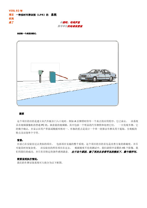
VISL 项目在完成了02年一种实时车牌识别(LPR)的系统由酒吧,母鸡罗恩指导单位约哈难埃雷兹该系统一个典型的模式:摘要这个项目的目的是建立从汽车板在门入口处时,例如A区牌照时停车一个真正的应用程序,它已承认。
该系统具有视频摄像机的普通PC机,渔获量的视频帧,其中包括一个明显的汽车牌照和处理它们。
一旦发现车牌,它的数字确认,并显示在用户界面或数据库核对一。
形象的重点是设计一个单一的算法车牌从用于提取,分离板的特点及识别单个字符。
背景:目前已在实验室过去类似的项目。
包括项目实施的整个系统。
这个项目的目的首先是改善方案的准确度,并尽可能其时间复杂度。
该实验室的所有项目在过去。
根据精度不佳的测试中,我们就程序设置的45个影像,我们用我们的成功,并只有在特定的条件感到满意。
出于这个原因,除了再次从非常罕见的情况下,整个程序写。
简要说明执行情况:我们的车牌识别系统可大致分为以下框图。
框图全球系统。
另外这个进程可以被看作是减少或地方的牌照抑制有害信息从携带信息的信号,这里是一个视频序列包含大量无关信息的特点,形式抽象符号的研究。
光学字符识别(OCR)已采用神经网络技术,采用神经元在输出层的前馈网络的3层,200个神经元在20输入层,中间神经元在10层,。
我们保留了神经网络数据集图像用在项目的先例,其中包括238位第我们的算法的详细步骤说明如下图:框图程序的子系统。
这里介绍捕获帧的一个给定的产出上面所述的主要步骤:示例捕获帧黄色区域捕获的帧过滤捕获帧地区扩张黄色车牌区域确定氡角度的变换板的使用改进的LP地区调整唱片轮廓-列和图调整唱片轮廓-线条和图唱片作物灰度唱片唱片二值化,均衡使用自适应阈值二进制唱片归唱片确定使用的LP水平轮廓图像总和先决行归唱片轮廓调节字符分割使用的山峰到山谷方法扩张型数位影像调整数字图像水平轮廓-线和图调整的数字图像轮廓调整大小的数字图像OCR的数字识别的神经网络方法工具该方案实施开发了基于Matlab。
汽车电子毕设设计外文文献翻译(适用于毕业论文外文翻译+中英文对照)

Ultrasonic ranging system designPublication title: Sensor Review. Bradford: 1993.Vol.ABSTRACT: Ultrasonic ranging technology has wide using worth in many fields, such as the industrial locale, vehicle navigation and sonar engineering. Now it has been used in level measurement, self-guided autonomous vehicles, fieldwork robots automotive navigation, air and underwater target detection, identification, location and so on. So there is an important practicing meaning to learn the ranging theory and ways deeply. To improve the precision of the ultrasonic ranging system in hand, satisfy the request of the engineering personnel for the ranging precision, the bound and the usage, a portable ultrasonic ranging system based on the single chip processor was developed.Keywords: Ultrasound, Ranging System, Single Chip Processor1. IntroductiveWith the development of science and technology, the improvement of people’s standard of living, speeding up the development and construction of the city. Urban drainage system have greatly developed their situation is construction improving. However, due to historical reasons many unpredictable factors in the synthesis of her time, the city drainage system. In particular drainage system often lags behind urban construction. Therefore, there are often good building excavation has been building facilities to upgrade the drainage system phenomenon. It brought to the city sewage, and it is clear to the city sewage and drainage culvert in the sewage treatment system.Co mfort is very important to people’s lives. Mobile robots designed to clear the drainage culvert and the automatic control system Free sewage culvert clear guarantee robots, the robot is designed to clear the culvert sewage to the core. Control system is the core component of the development of ultrasonic range finder. Therefore, it is very important to design a good ultrasonic range finder.2. A principle of ultrasonic distance measurementThe application of AT89C51:SCM is a major piece of computer components are integrated into the chip micro-computer. It is a multi-interface and counting on the micro-controller integration, and intelligence products are widely used in industrial automation. and MCS-51 microcontroller is a typical and representative.Microcontrollers are used in a multitude of commercial applications such as modems, motor-control systems, air conditioner control systems, automotive engine and among others. The high processing speed and enhanced peripheral set of these microcontrollers make them suitable for such high-speed event-based applications. However, these critical application domains also require that these microcontrollers are highly reliable. The high reliability and low market risks can be ensured by a robust testing process and a proper tools environment for the validation of these microcontrollers both at the component and at the system level. Intel Plaform Engineering department developed an object-oriented multi-threaded test environment for the validation of its AT89C51 automotive microcontrollers. The goals of this environment was not only to provide a robust testing environment for the AT89C51 automotive microcontrollers, but to develop an environment which can be easily extended and reused for the validation of several other future microcontrollers. The environment was developed in conjunction with Microsoft Foundation Classes(AT89C51).1.1 Features* Compatible with MCS-51 Products* 2Kbytes of Reprogrammable Flash MemoryEndurance: 1,000Write/Erase Cycles* 2.7V to 6V Operating Range* Fully Static operation: 0Hz to 24MHz* Two-level program memory lock* 128x8-bit internal RAM* 15programmable I/O lines* Two 16-bit timer/counters* Six interrupt sources*Programmable serial UART channel* Direct LED drive output* On-chip analog comparator* Low power idle and power down modes1.2 DescriptionThe AT89C2051 is a low-voltage, high-performance CMOS 8-bit microcomputer with 2Kbytes of flash programmable and erasable read only memory (PEROM). The device is manufactured using Atmel’s high density nonvolatile memory technology and is compatible with the industry standard MCS-51 instruction set and pinout. By combining a versatile 8-bit CPU with flash on a monolithic chip, the Atmel AT89C2051 is a powerful microcomputer which provides a highly flexible and cost effective solution to many embedded control applications.The AT89C2051 provides the following standard features: 2Kbytes of flash,128bytes of RAM, 15 I/O lines, two 16-bit timer/counters, a five vector two-level interrupt architecture, a full duplex serial port, a precision analog comparator, on-chip oscillator and clock circuitry. In addition, the AT89C2051 is designed with static logicfor operation down to zero frequency and supports two software selectable power saving modes. The idle mode stops the CPU while allowing the RAM, timer/counters, serial port and interrupt system to continue functioning. The power down mode saves the RAM contents but freezer the oscillator disabling all other chip functions until the next hardware reset.1.3 Pin Configuration1.4 Pin DescriptionVCC Supply voltage.GND Ground.Prot 1Prot 1 is an 8-bit bidirectional I/O port. Port pins P1.2 to P1.7 provide internal pullups. P1.0 and P1.1 require external pullups. P1.0 and P1.1 also serve as the positive input (AIN0) and the negative input (AIN1), respectively, of the on-chip precision analog comparator. The port 1 output buffers can sink 20mA and can drive LED displays directly. When 1s are written to port 1 pins, they can be used as inputs. When pins P1.2 to P1.7 are used as input and are externally pulled low, they will source current (IIL) because of the internal pullups.Port 3Port 3 pins P3.0 to P3.5, P3.7 are seven bidirectional I/O pins with internal pullups. P3.6 is hard-wired as an input to the output of the on-chip comparator and is not accessible as a general purpose I/O pin. The port 3 output buffers can sink 20mA. When 1s are written to port 3 pins they are pulled high by the internal pullups and can be used as inputs. As inputs, port 3 pins that are externally being pulled low will source current (IIL) because of the pullups.Port 3 also serves the functions of various special features of the AT89C2051 as listed below.1.5 Programming the FlashThe AT89C2051 is shipped with the 2 Kbytes of on-chip PEROM code memory array in the erased state (i.e., contents=FFH) and ready to be programmed. The code memory array is programmed one byte at a time. Once the array is programmed, to re-program any non-blank byte, the entire memory array needs to be erased electrically.Internal address counter: the AT89C2051 contains an internal PEROM address counter which is always reset to 000H on the rising edge of RST and is advanced applying a positive going pulse to pin XTAL1.Programming algorithm: to program the AT89C2051, the following sequence is recommended.1. power-up sequence:Apply power between VCC and GND pins Set RST and XTAL1 to GNDWith all other pins floating , wait for greater than 10 milliseconds2. Set pin RST to ‘H’ set pin P3.2 to ‘H’3. Apply the appropriate combination of ‘H’ or ‘L’ logic to pins P3.3, P3.4, P3.5,P3.7 to select one of the programming operations shown in the PEROM programming modes table.To program and Verify the Array:4. Apply data for code byte at location 000H to P1.0 to P1.7.5.Raise RST to 12V to enable programming.5. Pulse P3.2 once to program a byte in the PEROM array or the lock bits. The byte-write cycle is self-timed and typically takes 1.2ms.6. To verify the programmed data, lower RST from 12V to logic ‘H’ level and set pins P3.3 to P3.7 to the appropriate levels. Output data can be read at the port P1 pins.7. To program a byte at the next address location, pulse XTAL1 pin once to advance the internal address counter. Apply new data to the port P1 pins.8. Repeat steps 5 through 8, changing data and advancing the address counter for the entire 2 Kbytes array or until the end of the object file is reached.9. Power-off sequence: set XTAL1 to ‘L’ set RST to ‘L’Float all other I/O pins Turn VCC power off2.1 The principle of piezoelectric ultrasonic generatorPiezoelectric ultrasonic generator is the use of piezoelectric crystal resonators to work. Ultrasonic generator, the internal structure as shown, it has two piezoelectric chip and a resonance plate. When it’s two plus pulse signal, the frequency equal to the intrinsic piezoelectric oscillation frequency chip, the chip will happen piezoelectric resonance, and promote the development of plate vibration resonance, ultrasound is generated. Conversely, it will be for vibration suppression of piezoelectric chip, the mechanical energy is converted to electrical signals, then it becomes the ultrasonic receiver.The traditional way to determine the moment of the echo’s arrival is based on thresholding the received signal with a fixed reference. The threshold is chosen well above the noise level, whereas the moment of arrival of an echo is defined as the first moment the echo signal surpasses that threshold. The intensity of an echo reflecting from an object strongly depends on the object’s nature, size and distance from the sensor. Further, the time interval from the echo’s starting point to the moment when it surpasses the threshold changes with the intensity of the echo. As a consequence, a considerable error may occur even two echoes with different intensities arriving exactly at the same time will surpass the threshold at different moments. The stronger one will surpass the threshold earlier than the weaker, so it will be considered as belonging to a nearer object.2.2 The principle of ultrasonic distance measurementUltrasonic transmitter in a direction to launch ultrasound, in the moment to launch the beginning of time at the same time, the spread of ultrasound in the air, obstacles on his way to return immediately, the ultrasonic reflected wave received by the receiverimmediately stop the clock. Ultrasound in the air as the propagation velocity of 340m/s, according to the timer records the time t, we can calculate the distance between the launch distance barrier(s), that is: s=340t / 23. Ultrasonic Ranging System for the Second Circuit DesignSystem is characterized by single-chip microcomputer to control the use of ultrasonic transmitter and ultrasonic receiver since the launch from time to time, single-chip selection of 875, economic-to-use, and the chip has 4K of ROM, to facilitate programming.3.1 40 kHz ultrasonic pulse generated with the launchRanging system using the ultrasonic sensor of piezoelectric ceramic sensorsUCM40, its operating voltage of the pulse signal is 40kHz, which by the single-chip implementation of the following procedures to generate.puzel: mov 14h, # 12h; ultrasonic firing continued 200msHere: cpl p1.0; output 40kHz square wavenop;nop;nop;djnz 14h, here;retRanging in front of single-chip termination circuit P1.0 input port, single chip implementation of the above procedure, the P1.0 port in a 40kHz pulse output signal, after amplification transistor T, the drive to launch the first ultrasonic UCM40T, issued 40kHz ultrasonic pulse, and the continued launch of 200ms. Ranging the right and the left side of the circuit, respectively, then input port P1.1 and P1.2, the working principle and circuit in front of the same location.3.2 Reception and processing of ultrasonicUsed to receive the first launch of the first pair UCM40R, the ultrasonic pulse modulation signal into an alternating voltage, the op-amp amplification IC1A and after polarization IC1B to IC2. IC2 is locked loop with audio decoder chip LM567, internal voltage-controlled oscillator center frequency of f0=1/1.1R8C3, capacitor C4 determinetheir target bandwidth. R8-conditioning in the launch of the high jump 8 feet into a low-level, as interrupt request signals to the single-chip processing.Ranging in front of single-chip termination circuit output port INT0 interrupt the highest priority, right or left location of the output circuit with output gate IC3A access INT1 port single-chip, while single-chip P1.3 and P1.4 received input IC3A, interrupted by the process to identify the source of inquiry to deal with, interrupt priority level for the first left right after. Part of the source code is as follows:Receivel: push pswpush accclr ex1; related external interrupt 1jnb p1.1, right; P1.1 pin to 0, ranging from right to interrupt service routine circuitjnb p1.2, left; P1.2 pin to 0, to the left ranging circuit interrupt service routinereturn: SETB EX1; open external interrupt 1pop accpop pswretiright: …; right location entrance circuit interrupt service routineAjmp Returnleft: …; left ranging entrance circuit interrupt service routineAjmp Return3.3 The calculation of ultrasonic propagation timeWhen you start firing at the same time start the single-chip circuitry within the timer T0, the use of timer counting function records the time and the launch of ultrasonic reflected wave received time. When you receive the ultrasonic reflected wave, the receiver circuit output a negative jump in the end of INT0 or INT1 interrupt request generates a signal, single-chip microcomputer in response to external interrupt request, the implementation of the external interrupt service subroutine, read the time difference, calculating the distance. Some of its source code is as follows:RECEIVE0: PUSH PSWPUSH ACCCLR EX0; related external interrupt 0MOV R7, TH0; read the time valueMOV R6, TL0CLR CMOV A, R6SUBB A, #0BBH; calculate the time differenceMOV 31H, A; storage resultsMOV A, R7SUBB A, # 3CHMOV 30H, ASETB EX0; open external interrupt 0\POP ACCPOP PSWRETIFor a flat target, a distance measurement consists of two phases: a coarse measurement and a fine measurement:Step 1: Transmission of one pulse train to produce a simple ultrasonic wave.Step 2: Changing the gain of both echo amplifiers according to equation, until the echo is detected.Step 3: Detection of the amplitudes and zero-crossing times of both echoes.Step 4: Setting the gains of both echo amplifiers to normalize the output at, say 3 volts. Setting the period of the next pulses according to the: period of echoes. Setting the time window according to the data of step 2.Step 5: Sending two pulse trains to produce an interfered wave. Testing the zero-crossing times and amplitudes of the echoes. If phase inversion occurs in the echo, determine to otherwise calculate to by interpolation using the amplitudes near the trough. Derive t sub m1 and t sub m2.Step 6: Calculation of the distance y using equation.4、The ultrasonic ranging system software designSoftware is divided into two parts, the main program and interrupt service routine. Completion of the work of the main program is initialized, each sequence of ultrasonic transmitting and receiving control.Interrupt service routines from time to time to complete three of the rotation direction of ultrasonic launch, the main external interrupt service subroutine to read the value of completion time, distance calculation, the results of the output and so on.5、ConclusionsRequired measuring range of 30cm-200cm objects inside the plane to do a number of measurements found that the maximum error is 0.5cm, and good reproducibility. Single-chip design can be seen on the ultrasonic ranging system has a hardware structure is simple, reliable, small features such as measurement error. Therefore, it can be used not only for mobile robot can be used in other detection system.Thoughts: As for why the receiver do not have the transistor amplifier circuit, because the magnification well, integrated amplifier, but also with automatic gain control level, magnification to 76dB, the center frequency is 38k to 40k, is exactly resonant ultrasonic sensors frequency.6、Parking sensor6.1 Parking sensor introductionReversing radar, full name is "reversing the anti-collision radar, also known as" parking assist device, car parking or reversing the safety of assistive devices, ultrasonic sensors(commonly known as probes), controls and displays (or buzzer)and other components. To inform the driver around the obstacle to the sound or a moreintuitive display to lift the driver parking, reversing and start the vehicle around tovisit the distress caused by, and to help the driver to remove the vision deadends and blurred vision defects and improve driving safety.6.2 Reversing radar detection principleReversing radar, according to high-speed flight of the bats in thenight, not collided with any obstacle principles of design anddevelopment. Probe mounted on the rear bumper, according to different price and brand, the probe only ranging from two, three, four, six, eight,respectively, pipe around. The probe radiation, 45-degree angle up and downabout the search target. The greatest advantage is to explore lower than the bumper of the driver from the rear window is difficult to see obstacles, and the police, suchas flower beds, children playing in the squatting on the car.Display parking sensor installed in the rear view mirror, it constantlyremind drivers to car distance behindthe object distance to the dangerous distance, the buzzer starts singing, allow the driver to stop. When the gear lever linked into reverse gear, reversing radar, auto-start the work, the working range of 0.3 to 2.0 meters, so stop when the driver was very practical. Reversing radar is equivalent to an ultrasound probe for ultrasonic probe can be divided into two categories: First, Electrical, ultrasonic, the second is to use mechanical means to produce ultrasound, in view of the more commonly used piezoelectric ultrasonic generator, it has two power chips and a soundingboard, plus apulse signal when the poles, its frequency equal to the intrinsic oscillation frequency of the piezoelectric pressure chip will be resonant and drivenby the vibration of the sounding board, the mechanical energy into electrical signal, which became the ultrasonic probe works. In order to better study Ultrasonic and use up, people have to design and manufacture of ultrasonic sound, the ultrasonic probe tobe used in the use of car parking sensor. With this principle in a non-contactdetection technology for distance measurement is simple, convenient and rapid, easyto do real-time control, distance accuracy of practical industrial requirements. Parking sensor for ranging send out ultrasonic signal at a givenmoment, and shot in the face of the measured object back to the signal wave, reversing radar receiver to use statistics in the ultrasonic signal from the transmitter to receive echo signals calculate the propagation velocity in the medium, which can calculate the distance of the probe and to detect objects.6.3 Reversing radar functionality and performanceParking sensor can be divided into the LCD distance display, audible alarm, and azimuth directions, voice prompts, automatic probe detection function is complete, reversing radar distance, audible alarm, position-indicating function. A good performance reversing radar, its main properties include: (1) sensitivity, whether theresponse fast enough when there is an obstacle. (2) the existence of blind spots. (3) detection distance range.6.4 Each part of the roleReversing radar has the following effects: (1) ultrasonic sensor: used tolaunch and receive ultrasonic signals, ultrasonic sensors canmeasure distance. (2) host: after the launch of the sine wave pulse to the ultrasonic sensors, and process the received signal, to calculate the distance value, the data and monitor communication. (3) display or abuzzer: the receivinghost from the data, and display the distance value and provide differentlevels according to the distance from the alarm sound.6.5 Cautions1, the installation height: general ground: car before the installation of 45 ~55: 50 ~ 65cmcar after installation. 2, regular cleaningof the probe to prevent the fill. 3, do not use the hardstuff the probe surface cover will produce false positives or ranging allowed toprobe surface coverage, such as mud. 4, winter to avoid freezing. 5, 6 / 8 probe reversing radar before and after the probe is not free to swap may cause the ChangMing false positive problem. 6, note that the probe mounting orientation, in accordance with UP installation upward. 7, the probe is not recommended to install sheetmetal, sheet metal vibration will cause the probe resonance, resulting in false positives.超声测距系统设计原文出处:传感器文摘布拉福德:1993年超声测距技术在工业现场、车辆导航、水声工程等领域具有广泛的应用价值,目前已应用于物位测量、机器人自动导航以及空气中与水下的目标探测、识别、定位等场合。
汽车车牌识别系统毕业论文(带外文翻译)解析
汽车车牌识别系统---车牌定位子系统的设计与实现摘要汽车车牌识别系统是近几年发展起来的计算机视觉和模式识别技术在智能交通领域应用的重要研究课题之一。
在车牌自动识别系统中,首先要将车牌从所获取的图像中分割出来实现车牌定位,这是进行车牌字符识别的重要步骤,定位的准确与否直接影响车牌识别率。
本次毕业设计首先对车牌识别系统的现状和已有的技术进行了深入的研究,在此基础上设计并开发了一个基于MATLAB的车牌定位系统,通过编写MATLAB文件,对各种车辆图像处理方法进行分析、比较,最终确定了车牌预处理、车牌粗定位和精定位的方法。
本次设计采取的是基于微分的边缘检测,先从经过边缘提取后的车辆图像中提取车牌特征,进行分析处理,从而初步定出车牌的区域,再利用车牌的先验知识和分布特征对车牌区域二值化图像进行处理,从而得到车牌的精确区域,并且取得了较好的定位结果。
关键词:图像采集,图像预处理,边缘检测,二值化,车牌定位ENGLISH SUBJECTABSTRACTThe subject of the automatic recognition of license plate is one of the most significant subjects that are improved from the connection of computer vision and pattern recognition. In LPSR, the first step is for locating the license plate in the captured image which is very important for character recognition. The recognition correction rate of license plate is governed by accurate degree of license plate location.Firstly, the paper gives a deep research on the status and technique of the plate license recognition system. On the basis of research, a solution of plate license recognition system is proposed through the software MATLAB,by the M-files several of methods in image manipulation are compared and analyzed. The methods based on edge map and das differential analysis is used in the process of the localization of the license plate,extracting the characteristics of the license plate in the car images after being checked up for the edge, and then analyzing and processing until the probably area of license plate is extracted,then come out the resolutions for localization of the car plate.KEY WORDS:imageacquisition,image preprocessing,edge detection,binarization,licence,license plate location目录前言 (1)第1章绪论 (2)§1.1 课题研究的背景 (2)§1.2 车牌的特征 (2)§1.3 国内外车辆牌照识别技术现状 (3)§1.4车牌识别技术的应用情况 (4)§1.5 车牌识别技术的发展趋势 (5)§1.6车牌定位的意义 (6)第2章MATLAB简介 (7)§2.1 MATLAB发展历史 (7)§2.2 MATLAB的语言特点 (7)第3章图像预处理 (10)§3.1 灰度变换 (10)§3.2 图像增强 (11)§3. 3 图像边缘提取及二值化 (13)§3. 4 形态学滤波 (18)第4章车牌定位 (21)§4.1 车牌定位的主要方法 (21)§4.1.1基于直线检测的方法 (22)§4.1.2 基于阈值化的方法 (22)§4.1.3 基于灰度边缘检测方法 (22)§4.1.4 基于彩色图像的车牌定位方法 (25)§4.2 车牌提取 (26)结论 (30)参考文献 (31)致谢 (33)前言随着交通问题的日益严重,智能交通系统应运而生。
智能控制系统毕业论文中英文资料对照外文翻译文献
智能控制系统中英文资料对照外文翻译文献附录一:外文摘要The development and application of Intelligence controlsystemModern electronic products change rapidly is increasingly profound impact on people's lives, to people's life and working way to bring more convenience to our daily lives, all aspects of electronic products in the shadow, single chip as one of the most important applications, in many ways it has the inestimable role. Intelligent control is a single chip, intelligent control of applications and prospects are very broad, the use of modern technology tools to develop an intelligent, relatively complete functional software to achieve intelligent control system has become an imminent task. Especially in today with MCU based intelligent control technology in the era, to establish their own practical control system has a far-reaching significance so well on the subject later more fully understanding of SCM are of great help to.The so-called intelligent monitoring technology is that:" the automatic analysis and processing of the information of the monitored device". If the monitored object as one's field of vision, and intelligent monitoring equipment can be regarded as the human brain. Intelligent monitoring with the aid of computer data processing capacity of the powerful, to get information in the mass data to carry on the analysis, some filtering of irrelevant information, only provide some key information. Intelligent control to digital, intelligent basis, timely detection system in the abnormal condition, and can be the fastest and best way to sound the alarm and provide usefulinformation, which can more effectively assist the security personnel to deal with the crisis, and minimize the damage and loss, it has great practical significance, some risk homework, or artificial unable to complete the operation, can be used to realize intelligent device, which solves a lot of artificial can not solve the problem, I think, with the development of the society, intelligent load in all aspects of social life play an important reuse.Single chip microcomputer as the core of control and monitoring systems, the system structure, design thought, design method and the traditional control system has essential distinction. In the traditional control or monitoring system, control or monitoring parameters of circuit, through the mechanical device directly to the monitored parameters to regulate and control, in the single-chip microcomputer as the core of the control system, the control parameters and controlled parameters are not directly change, but the control parameter is transformed into a digital signal input to the microcontroller, the microcontroller according to its output signal to control the controlled object, as intelligent load monitoring test, is the use of single-chip I / O port output signal of relay control, then the load to control or monitor, thus similar to any one single chip control system structure, often simplified to input part, an output part and an electronic control unit ( ECU )Intelligent monitoring system design principle function as follows: the power supply module is 0~220V AC voltage into a0 ~ 5V DC low voltage, as each module to provide normal working voltage, another set of ADC module work limit voltage of 5V, if the input voltage is greater than 5V, it can not work normally ( but the design is provided for the load voltage in the 0~ 5V, so it will not be considered ), at the same time transformer on load current is sampled on the accused, the load current into a voltage signal, and then through the current - voltage conversion, and passes through the bridge rectification into stable voltage value, will realize the load the current value is converted to a single chip can handle0 ~ 5V voltage value, then the D2diode cutoff, power supply module only plays the role of power supply. Signal to the analog-to-digital conversion module, through quantization, coding, the analog voltage value into8bits of the digital voltage value, repeatedly to the analog voltage16AD conversion, and the16the digital voltage value and, to calculate the average value, the average value through a data bus to send AT89C51P0, accepted AT89C51 read, AT89C51will read the digital signal and software setting load normal working voltage reference range [VMIN, VMAX] compared with the reference voltage range, if not consistent, then the P1.0 output low level, close the relay, cut off the load on the fault source, to stop its sampling, while P1.1 output high level fault light, i.e., P1.3 output low level, namely normal lights. The relay is disconnected after about 2minutes, theAT89C51P1.0outputs high level ( software design), automatic closing relay, then to load the current regular sampling, AD conversion, to accept the AT89C51read, comparison, if consistent, then the P1.1 output low level, namely fault lights out, while P1.3 output high level, i.e. normal lamp ( software set ); if you are still inconsistent, then the need to manually switch S1toss to" repair" the slip, disconnect the relay control, load adjusting the resistance value is: the load detection and repair, and then close the S1repeatedly to the load current sampling, until the normal lamp bright, repeated this process, constantly on the load testing to ensure the load problems timely repair, make it work.In the intelligent load monitoring system, using the monolithic integrated circuit to the load ( voltage too high or too small ) intelligent detection and control, is achieved by controlling the relay and transformer sampling to achieve, in fact direct control of single-chip is the working state of the relay and the alarm circuit working state, the system should achieve technical features of this thesis are as follows (1) according to the load current changes to control relays, the control parameter is the load current, is the control parameter is the relay switch on-off and led the state; (2) the set current reference voltage range ( load normal working voltage range ), by AT89C51 chip the design of the software section, provide a basis for comparison; (3) the use of single-chip microcomputer to control the light-emitting diode to display the current state of change ( normal / fault / repair ); specific summary: Transformer on load current is sampled, a current / voltage converter, filter, regulator, through the analog-digital conversion, to accept the AT89C51chip to read, AT89C51 to read data is compared with the reference voltage, if normal, the normal light, the output port P.0high level, the relay is closed, is provided to the load voltage fault light; otherwise, P1.0 output low level, The disconnecting relay to disconnect the load, the voltage on the sampling, stop. Two minutes after closing relay, timing sampling.System through the expansion of improved, can be used for temperature alarm circuit, alarm circuit, traffic monitoring, can also be used to monitor a system works, in the intelligent high-speed development today, the use of modern technology tools, the development of an intelligent, function relatively complete software to realize intelligent control system, has become an imminent task, establish their own practical control system has a far-reaching significance. Micro controller in the industry design and application, no industry like intelligent automation and control field develop so fast. Since China and the Asian region the main manufacturing plant intelligence to improve the degree of automation, new technology to improve efficiency, have important influence on the product cost. Although the centralized control can be improved in any particular manufacturing process of the overall visual, but not for those response and processingdelay caused by fault of some key application.Intelligent control technology as computer technology is an important technology, widely used in industrial control, intelligent control, instrument, household appliances, electronic toys and other fields, it has small, multiple functions, low price, convenient use, the advantages of a flexible system design. Therefore, more and more engineering staff of all ages, so this graduate design is of great significance to the design of various things, I have great interest in design, this has brought me a lot of things, let me from unsuspectingly to have a clear train of thought, since both design something, I will be there a how to design thinking, this is very important, I think this job will give me a lot of valuable things.中文翻译:智能控制系统的开发应用现代社会电子产品日新月异正在越来越深远的影响着人们的生活,给人们的生活和工作方式带来越来越大的方便,我们的日常生活各个方面都有电子产品的影子,单片机作为其中一个最重要的应用,在很多方面都有着不可估量的作用。
- 1、下载文档前请自行甄别文档内容的完整性,平台不提供额外的编辑、内容补充、找答案等附加服务。
- 2、"仅部分预览"的文档,不可在线预览部分如存在完整性等问题,可反馈申请退款(可完整预览的文档不适用该条件!)。
- 3、如文档侵犯您的权益,请联系客服反馈,我们会尽快为您处理(人工客服工作时间:9:00-18:30)。
汽车牌照自动识别系统中英文对照外文翻译文献(文档含英文原文和中文翻译)Automatic vehicle license plate recognition systemImage processing is not a one step process.We are able to distinguish between several steps which must be performed one after the other until we can extract the data of interest from the observed scene.In this way a hierarchical processing scheme is built up as sketched in Fig.The figure gives an overview of the different phases of image processing.Image processing begins with the capture of an image with a suitable,not necessarily optical,acquisition system.In a technical or scientific application,we may choose to select an appropriate imaging system.Furthermore,we can set up the illumination system,choose the best wavelength range,and select other options to capture the object feature of interest in the best way in an image.Once the image is sensed,it must be brought into a form that can be treated with digital computers.This process is called digitization.With the problems of traffic are more and more serious. Thus Intelligent Transport System (ITS) comes out. The subject of the automatic recognition of license plate is one of the most significant subjects that are improved from the connection of computer vision and pattern recognition. The image imputed to the computer is disposed and analyzed in order to localization the position and recognition the characters on the license plate express these characters in text string form The license plate recognition system (LPSR) has important application in ITS. In LPSR, the first step is for locating the license plate in the captured image which is very important for character recognition. The recognition correction rate of license plate is governed by accurate degree of license plate location. In this paper, several of methods in image manipulation are compared and analyzed, then come out the resolutions for localization of the car plate. The experiences show that the good result has been got with thesemethods. The methods based on edge map and frequency analysis is used in the process of the localization of the license plate, that is to say, extracting the characteristics of the license plate in the car images after being checked up for the edge, and then analyzing and processing until the probably area of license plate is extracted.The automated license plate location is a part of the image processing ,it’s also an important part in the intelligent traffic system.It is the key step in the Vehicle License Plate Recognition(LPR).A method for the recognition of images of different backgrounds and different illuminations is proposed in the paper.the upper and lower borders are determined through the gray variation regulation of the character distribution.The left and right borders are determined through the black-white variation of the pixels in every row.The first steps of digital processing may include a number of different operations and are known as image processing.If the sensor has nonlinear characteristics, these need to be corrected.Likewise,brightness and contrast of the image may require improvement.Commonly,too,coordinate transformations are needed to restore geometrical distortions introduced during image formation.Radiometric and geometric corrections are elementary pixel processing operations.It may be necessary to correct known disturbances in the image,for instance caused by a defocused optics,motion blur,errors in the sensor,or errors in the transmission of image signals.We also deal with reconstruction techniques which are required with many indirect imaging techniques such as tomography that deliver no direct image.A whole chain of processing steps is necessary to analyze and identify objects.First,adequate filtering procedures must be applied in order to distinguish the objects of interest from other objects and the background.Essentially,from an image(or several images),one or more feature images are extracted.The basic tools for this task are averaging and edgedetection and the analysis of simple neighborhoods and complex patterns known as texture in image processing.An important feature of an object is also its motion.Techniques to detect and determine motion are necessary.Then the object has to be separated from the background.This means that regions of constant features and discontinuities must be identified.This process leads to a label image.Now that we know the exact geometrical shape of the object,we can extract further information such as the mean gray value,the area,perimeter,and other parameters for the form of the object[3].These parameters can be used to classify objects.This is an important step in many applications of image processing,as the following examples show:In a satellite image showing an agricultural area,we would like to distinguish fields with different fruits and obtain parameters to estimate their ripeness or to detect damage by parasites.There are many medical applications where the essential problem is to detect pathologi-al changes.A classic example is the analysis of aberrations in chromosomes.Character recognition in printed and handwritten text is another example which has been studied since image processing began and still poses significant difficulties.You hopefully do more,namely try to understand the meaning of what you are reading.This is also the final step of image processing,where one aims to understand the observed scene.We perform this task more or less unconsciously whenever we use our visual system.We recognize people,we can easily distinguish between the image of a scientific lab and that of a living room,and we watch the traffic to cross a street safely.We all do this without knowing how the visual system works.For some times now,image processing and computer-graphics have been treated as two different areas.Knowledge in both areas has increased considerably and more complex problems can now be treated.Computer graphics is striving to achieve photorealistic computer-generated images of three-dimensional scenes,while image processing is trying to reconstruct one from an image actually taken with a camera.In thissense,image processing performs the inverse procedure to that of computer graphics.We start with knowledge of the shape and features of an object—at the bottom of Fig. and work upwards until we get a two-dimensional image.To handle image processing or computer graphics,we basically have to work from the same knowledge.We need to know the interaction between illumination and objects,how a three-dimensional scene is projected onto an image plane,etc.There are still quite a few differences between an image processing and a graphics workstation.But we can envisage that,when the similarities and interrelations between computergraphics and image processing are better understood and the proper hardware is developed,we will see some kind of general-purpose workstation in the future which can handle computer graphics as well as image processing tasks[5].The advent of multimedia,i. e. ,the integration of text,images,sound,and movies,will further accelerate the unification of computer graphics and image processing.In January 1980 Scientific American published a remarkable image called Plume2,the second of eight volcanic eruptions detected on the Jovian moon by the spacecraft Voyager 1 on 5 March 1979.The picture was a landmark image in interplanetary exploration—the first time an erupting volcano had been seen in space.It was also a triumph for image processing.Satellite imagery and images from interplanetary explorers have until fairly recently been the major users of image processing techniques,where a computer image is numerically manipulated to produce some desired effect-such as making a particular aspect or feature in the image more visible.Image processing has its roots in photo reconnaissance in the Second World War where processing operations were optical and interpretation operations were performed by humans who undertook such tasks as quantifying the effect of bombing raids.With the advent of satellite imagery in the late 1960s,much computer-based work began and the color composite satellite images,sometimesstartlingly beautiful, have become part of our visual culture and the perception of our planet.Like computer graphics,it was until recently confined to research laboratories which could afford the expensive image processing computers that could cope with the substantial processing overheads required to process large numbers of high-resolution images.With the advent of cheap powerful computers and image collection devices like digital cameras and scanners,we have seen a migration of image processing techniques into the public domain.Classical image processing techniques are routinely employed by graphic designers to manipulate photographic and generated imagery,either to correct defects,change color and so on or creatively to transform the entire look of an image by subjecting it to some operation such as edge enhancement.A recent mainstream application of image processing is the compression of images—either for transmission across the Internet or the compression of moving video images in video telephony and video conferencing.Video telephony is one of the current crossover areas that employ both computer graphics and classical image processing techniques to try to achieve very high compression rates.All this is part of an inexorable trend towards the digital representation of images.Indeed that most powerful image form of the twentieth century—the TV image—is also about to be taken into the digital domain.Image processing is characterized by a large number of algorithms that are specific solutions to specific problems.Some are mathematical or context-independent operations that are applied to each and every pixel.For example,we can use Fourier transforms to perform image filtering operations.Others are“algorithmic”—we may use a complicated recursive strategy to find those pixels that constitute the edges in an image.Image processing operations often form part of a computer vision system.The input image may be filtered to highlight or reveal edges prior to ashape detection usually known as low-level operations.In computer graphics filtering operations are used extensively to avoid abasing or sampling artifacts.翻译:汽车牌照自动识别系统图像处理不是一步就能完成的过程。