TT服务工具手册
TT使用简介_56-133_pdf

in service
(03XX涉及门操作控制方面)
in service
21
LCB/TCB/TCBC __操作控制子系统
TCBC/GECB故障记录M-1-2-1
in service
(04XX与05XX涉及RS与群控 方面)
in service
22
66
LCB/TCB/TCBC __操作控制子系统
in service
3
OCSS__操作控制子系统
事件号 事件描述 软件自测方面的记录 1000 POWERED ON 1001 POWER FAILURE 1002 NUMBER OF RUNS 1100 HARDWARE RESET 1101 SOFTWARE RESET 1102 ILLEGAL INTERRUP 1103 RING COMM RESET MCSS通讯方面的记录 1200 MCSS MSG CHCKSUM 1201 MCSS MSG TIMEOUT 1202 MCSS MSG SIO ERR SPB通讯方面的记录 1300 SPB MSG CHECKSUM 1301 SPB MSG TIMEOUT 1302 SPB MSG SIO ERR 1303 SPB ENCODER FLT 1304 SPB BATTERY FLT 远程端站长通讯方面的记录 1400 RSLC LOST SYNCH 1401 RSLH LOST SYNCH 1402 RSLG LOST SYNCH 1403 RSLC PARITY ERR 1404 RSLH PARITY ERR 1405 RSLG PARITY ERR 解释 电源开启 电源关闭 运行次数 硬件重置 软件重置 非法中断 环型重置 事件号 事件描述 环型通讯方面的记录 1500 RNG1 MSG CHCKSUM 1501 RNG1 MSG TIMEOUT 1502 RNG1 MSG SIO ERR 1503 RNG2 MSG CHCKSUM 1504 RNG2 MSG TIMEOUT 1505 RNG2 MSG SIO ERR
TT测试工具的使用方法
OTIS (TT)测试工具的使用方法☆Toec-40调试方法[概要] 由于本工具可与若干种OTIS 公司的电梯(如:TOEC-40 TOEC-60等)连接。
本说明书仅以与TOEC-40 型电梯相连时为例,与其它电梯相连时略有不同。
测试工具接在LB(逻辑板)上,因此它可以一边登记一边检查轿厢的状况和各个输入输出。
[功能]1.LED 检查2.各状态的显示(轿厢状况,门状况,轿厢位置,方向,呼梯)3.呼梯的登记4.输入的显示5.输出的操作6.各轿厢的状况(组件)7.存储器(RAM)内存内容的显示[显示部]显示窗:有16×2个LCD显示屏,显示出英文和数字。
[键][MOUDULE] 对线路板进行选择。
[DISP STATE] 显示轿厢状况,门状况。
[ENT CALL] 登记呼梯。
[TEST] 不用。
[FUNTION] 不用。
[DISP IN] 输入显示。
[SEL OUT] 输出操作。
[0] ~[9] 呼梯登记的楼层输入。
[SET] 不用。
[ON] 使输出接通。
[UP] [DOWN] 上,下呼梯。
[蓝键] 换档键。
[OFF] 使输出断开。
[GO ON] 显示后面的输入,输出状况。
[GO BACK] 显示后面的输入,输出状况。
使用方法1.LCD 检查(自身测试)[功能] 实验LCD的显示机能[使用方法](1)由于接通LB(逻辑板),自动开始LCD顺次点灯实验。
(2)在使用实验工具进行的情况下,按动红色的转换开关。
2.轿厢状况,门状况的显示:[功能] 显示轿厢状况,门状况,轿厢位置,方向,各个呼梯。
[使用方法] 按动{DISP STATE}[显示]★★★★★★★★单台的场合★★★★★★★★Page.2轿厢的方向轿厢状况门状况1)轿厢方向向上▲向下▼无方向第一行LCD轿厢位置第二行LCD轿厢呼唤第三行LCD大厅下呼唤第四行LCD大厅上呼唤2)轿厢状况TRV? 继电器操作电路的交流100V电源脱落。
CORR? 校正运行开始前的等待状况,等5秒后便开始校正运行。
VirtualBox中文技术手册

VirtualBox中文技术手册VirtualBox中文技术手册由于在2010年收购了Sun公司,甲骨文获得了VirtualBox平台。
虽然Oracle VirtualBox常用于桌面虚拟化部署,但也适合虚拟服务器环境。
在本期TT虚拟化技术手册中,我们将介绍VirtualBox快照、VirtualBox在虚拟化平台、P2V迁移设备方面提供的信息,还会介绍设置USB设备的过程。
快速认识VirtualBox当谈到基于主机的虚拟化,IT人士通常转向两个平台:VMware Workstation 7和Sun xVM VirtualBox。
关于VirtualBox vs. VMware Workstation的比较信息,请看我们TechTarget虚拟化专家的面对面讨论。
专家面对面:Sun xVM VirtualBox vs. VMware WorkstationVirtualBox功能集合VirtualBox有哪些主要的功能?比如Guest Additions有何作用?共享文件夹如何使用?VirtualBox快照又该如何使用?本部分将详细介绍这些功能。
Sun xVM VirtualBox Guest Additions功能解析Sun xVM VirtualBox之共享文件夹功能VirtualBox功能之VRDP部署Sun xVM VirtualBox快照功能简介VirtualBox网络桥接功能简介VirtualBox迁移功能这系列两部分文章详细介绍Sun公司VirtualBox hypervisor的P2V转换选项。
第一部分主要介绍如何为VirtualBox转换准备VMware虚拟机。
第二部分将介绍驱动安装、管理和其他的转换问题。
Sun VirtualBox P2V服务器转换过程实战轻松搞定VirtualBox P2V转换遇到的难题VirtualBox实用技巧用于Windows的Sun xVM VirtualBox提供了一种功能:将基于VMware的VMDK文件输入到虚拟机,这使得迁移和跨平台部署更为诱人。
TT快速入门手册2说明书
INDEXSECTION 1: General information•Power switch•Control panel•Passwords•Safety sensors•Stop button on the touch screenSECTION 2: Filling the pump•Purpose of filling pump•Roller Head•Pump HeadSECTION 3: Lowering and lifting table •Step by step instructionSECTION 4: Preprogrammed Recipes•25-30 Preprogrammed recipes•Copying and saving under a new name SECTION 5: Placing traysSECTION 6: Starting productionSECTION 7: Cleaning•Step by step instructions on breakdown for cleaning Section 8: ReassemblySection 9: Standard recipesSection 10: Adjusting recipesSECTION 1: General information1. The power switch is located on the back side of the machine2.Control panel description3. Passwords:∙Operator password 654321∙Supervisor password 4149904. Safety Sensors: There are three safety sensors on the machine∙Two proximity sensors ( Front and back of hopper)∙ 1 magnetic sensor on the hopper (Cover of the hopper)(Proximity Sensors)(Magnetic Sensor)*Note: Interrupting the sensors will stop the machine. To reset press the start switch, if it doesn’t r eset by pushing the green start button first unlock the emergency stop button by twisting to the right (it should pop out)5.Stop function on the touch screen: The operator can use this function in two ways5.1Press the stop tab to pause depositing briefly, then push start tab on touchscreen to resume depositing where it left off.5.2Press and hold the stop tab on the touch screen for 5 seconds it will stop, ejectthe tray and instruct you to push start. Push start and it will begin a new cycle.(5.1)(5.2)SECTION 2: Filling the pumpWhen starting production with batter in the hopper, the pump is empty. You couldmanually run the pump before starting production cycle will deposit the batter until pump is filled, ensuring your first tray of product will be complete. Once the pump has adequate amount of batter it will deposit a consistent stream. Now you can begin production.1. Add your batter to the hopper ( Be sure to close the lid properly)2. Place a tray on the conveyor to catch any batter under the nozzles3. Select Pump head for semi liquid batters.a. i.e. Macarons, Choux, éclairs, muffins• Using the touch screen press the wrench icon, then the pointing handicon. (The screen display should match the picture below.) Based on the batter select the correct pump and hold for a few seconds until your batter runs though the pump. Once the pump is depositing a consistent product you are ready to begin production.4. Select Roller head for dough like batters.a. i.e. Butter cookies• Same steps as described above.**Note: Roller head motion isinward, whereas Pump headmotion is outward.SECTION 3: Lowering and lifting the tableTo manually move the table up or down follow these instructions:1. Press the wrench icon on the touch screen2. Press the pointing hand icon3. Select the blue table tab4. The choice of up or down will pop up, just press and hold in the desired direction.SECTION 4: Pre-programmed RecipesThe machine has room for 30 PROGRAMS (recipes). Six of these programs are BASIC—EXAMPLE recipes factory set in order to make the programming easy and user-friendly. They can be found in position 25 to 30.Recipe N° Name Drop Picture25 FIX FIX DROP26 FIX FIX DROPTWISTED W/ NOZZLEROTATION27 LONG DROP long drop28 LONG long drop w/TWISTED nozzle rotation29 WIRE CUT drop cut30 WIRE CUT long dropLONG cutSECTION 4: Recipes Continued1. Selecting a preprogrammed recipe:∙Press the Recipe book icon and enter the recipe list, navigate through the recipe’s using the blue arrows and choose the recipe. Press the recipe tohighlight the tab.∙Press the green arrow icon a box will pop up, push yes to confirm (The name on the grey line will match the name on the yellow line)∙Press the home icon2. Copying a preprogrammed recipe:∙Return into the recipe index by following the steps above∙Select the recipe you’d like to copy. Press the recipe to highlight it yellow.∙Hit the floppy disc icon, a box will pop up select Yes. You have successfully copied that recipe.∙Look for and select a blank spot to paste the copied recipe, select that spot by press to highlight it yellow.∙Press the Disc icon, key in the password.∙Press the disc icon, yes to confirm. You have saved that recipe, now you can rename it.3. Renaming the copied recipe∙Select the recipe you just copied and pasted by pressing the yellow tab where it is located∙Once in the recipe, press the highlighted tab where the name is displayed. A keypad will pop up∙Using the keypad type in the name you would like to use for this recipe. Hit the enter button on the keypad.∙Now you are able to modify all the data for that recipe without effecting the original that was copied.SECTION 5: Placing trays1. Press the green START button on the touch screen; the machine starts cycle aGreen tab will turn on display “IN CYCLE”. The conveyor starts running and theMachine is ready to deposit.2. Place a tray on the conveyor, make sure you use only flat trays, the tray startsmoving forward and when it reaches the tray Sensor the dosing cycle will start.Based on the pan configuration programmed (example: 9 rows) the cycle will stop once completed, if no other trays are placed. If other trays are placed after the first one, the tray coming out from the conveyor must be collected by the operator.Make sure to leave 2 inches of space when placing the next tray, in order for the tray sensor to come up.3 The guide can be adjusted vertical and horizontal. Make sure the guide is always lower than the conveyer.SECTION 6: Starting production1. Turn on machine and press the touch screen2. Place a tray under the nozzle to collect batter while filling the pump3. Fill the hopper4. Reset (once hopper lid is properly closed)5. Fill the pump manually (see section 2)6. Remove collecting tray once all the nozzles are full7. Press start8. Place a tray on the belt and the machine will start depositing9. Place the next tray if you want to continue depositing, make sure you leave 2inches distance between trays.SECTION 7: Cleaning1. Place tray under depositor, run the pump manually (see section 2) until as muchbatter as possible is deposited.2. Carefully remove the hopper, pump, nozzles. Wash with soap and water. Be sureto dry thoroughly. (See below for step by step removing)1. Replace the seal for the Hopper. Be sure to pay special attention to theplacement of the seal. It should be flush with the hopper.Incorrect placementCorrect placement2. Replace the hopper, be sure to pay special attention to the placement. The widerpart of the Hopper should be the back side ( The back is where the power button is)Incorrect placementSection 9: Standard recipesSection 10: Adjusting recipesPress on the product to go into the recipeWith depositing time you can in- or decrease the size of the product.Pan; determines how many rows you want on the tray, the distance from the edge of the tray for the first deposit and the distance between rows.Table: height of the table is the height between the tray and the spouts at the time of depositSuction: after each deposit rollers reverse a little bit while the tray moves forwardAdvanced: tip off only used for depositing of eclairs.Press blue arrow to back to product screenYou can either deposit now and save settings later, or save settings now. To save now press on bookPress on the disk and enter your passcodePress disk againconfirm saving new settingsGo back to home。
奥的斯TT使用手册
奥的斯TT使用手册(LCBII/60/40)Test Tool (TT)测试工具的使用方法 Page.1☆ Toec-40调试方法[概要] 由于本工具可与若干种OTIS 公司的电梯(如:TOEC-40 TOEC-60等)连接。
本说明书仅以与TOEC-40 型电梯相连时为例,与其它电梯相连时略有不同。
测试工具接在LB(逻辑板)上,因此它可以一边登记一边检查轿厢的状况和各个输入输出。
[功能]1. LED 检查2. 各状态的显示(轿厢状况,门状况,轿厢位置,方向,呼梯)3. 呼梯的登记4. 输入的显示5. 输出的操作6. 各轿厢的状况(组件)7. 存储器(RAM)内存内容的显示[显示部]显示窗:有16×2个LCD显示屏,显示出英文和数字。
[键][MOUDULE] 对线路板进行选择。
[DISP STATE] 显示轿厢状况,门状况。
[ENT CALL] 登记呼梯。
[TEST] 不用。
[FUNTION] 不用。
[DISP IN] 输入显示。
[SEL OUT] 输出操作。
[0] ~[9] 呼梯登记的楼层输入。
[SET] 不用。
[ON] 使输出接通。
[UP] [DOWN] 上,下呼梯。
[蓝键] 换档键。
[OFF] 使输出断开。
[GO ON] 显示后面的输入,输出状况。
[GO BACK] 显示后面的输入,输出状况。
使用方法1.LCD 检查(自身测试)[功能] 实验LCD的显示机能[使用方法](1)由于接通LB(逻辑板),自动开始LCD顺次点灯实验。
(2)在使用实验工具进行的情况下,按动红色的转换开关。
2.轿厢状况,门状况的显示:[功能] 显示轿厢状况,门状况,轿厢位置,方向,各个呼梯。
[使用方法] 按动{DISP STATE}[显示]★★★★★★★★单台的场合★★★★★★★★ Page.2轿厢的方向轿厢状况门状况1)轿厢方向向上▲向下▼无方向第一行 LCD轿厢位置第二行LCD轿厢呼唤第三行LCD大厅下呼唤第四行LCD大厅上呼唤2)轿厢状况TRV? 继电器操作电路的交流100V电源脱落。
TT-2D 用户手册说明书
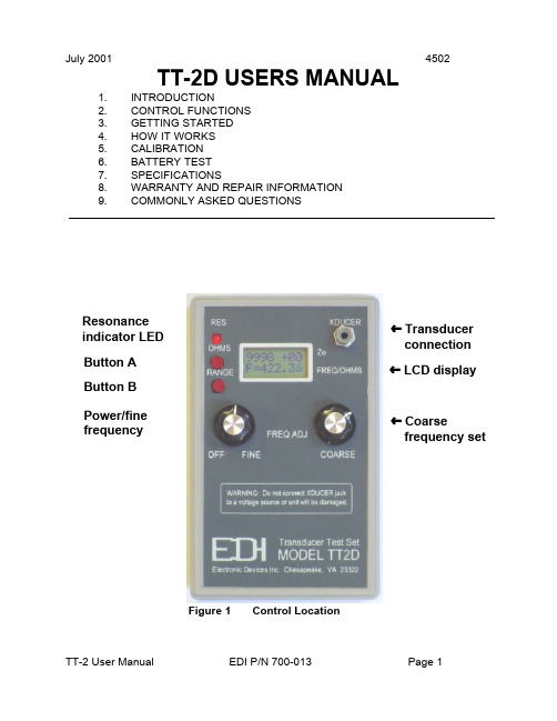
» LCD display » Transducer connection Figure 1 Control LocationPower/finefrequency ºButton A ºButton B ºResonanceindicator LED º» Coarsefrequency setJuly 20014502TT-2D USERS MANUAL1.INTRODUCTION 2.CONTROL FUNCTIONS 3.GETTING STARTED 4.HOW IT WORKS 5.CALIBRATION 6.BATTERY TEST 7.SPECIFICATIONS 8.WARRANTY AND REPAIR INFORMATION MONLY ASKED QUESTIONS1INTRODUCTIONThe TT-2D is designed to test acoustic transducers for resonance over the frequency range of 500 Hz to 500 KHz. The TT-2D tests all types of transducers, including transformer-coupled and magnetostrictive devices. The load characteristic (capacitive, resistive, or inductive) and impedance at resonance are displayed on the two line LCD display. The leakage resistance of the transducer can be measured and displayed over the range of 10 ohms to 5 megohms.2CONTROL FUNCTIONSRefer to figure 1 for the location of the controls discussed in this section.2.01TRANSDUCER CONNECTIONThe transducer output connects to the transducer under test. WARNING, donot connect a source of power to this connector. If you do, the TT-2D will be seriously damaged. This is an output only.2.02LCD DISPLAYNormally displays the frequency on the lower line and the impedance andrelative phase on the upper line. Battery voltage and software version aredisplayed for 3 seconds when the power is turned on.2.03COARSE FREQUENCY SET KNOBThis controls the frequency sent to the transducer from less than 500 Hz to over 500 KHz.2.04POWER/FINE FREQUENCY SWITCHThis knob controls the power and is also used to fine tune the frequency setting.The frequency range is about 10% of that set by the coarse frequency control. 2.05BUTTON AThe main function of this push button switch is to select the resistancemeasuring mode. When this button is pressed, the DC resistance of thetransducer is displayed in ohms on the bottom line of the display. The rangecovers 10 ohms to 5 megohms. Press button ‘B’ once to return to normaloperation.2.05.01During power-up, press button ‘A’ to increase the display contrast.2.06BUTTON BThe main function of this push button switch is to select one of the threefrequency ranges. The range increments each time this button is pressed. Each range covers a decade as shown below:2.06.00.01Range 1:500 Hz to 5 KHz.2.06.00.02Range 2: 5 KHz to 50 KHz.2.06.00.03Range 3:50 KHz to 500 KHz.2.06.01During power-up, press button ‘B’ to decrease the display contrast.2.06.02To make a selected frequency range as the default range, selectthe range and before releasing button ‘B’, press button ‘A’.Release both buttons when the display shows ‘FR store’ on thebottom line. This range will be selected each time the TT-2D ispowered-up.2.07RESONANCE INDICATORThis LED brightens when the frequency approaches the resonant point of thetransducer. The brighter the LED, the lower the impedance is. The LED alsoflashes on power-up while the TT-2D initiates the self-test routine.3GETTING STARTEDConnect the TT-2D XDUCER output to a transducer. Turn the power on and the TT-2D will go through a self-test routine while displaying the battery voltage. While the TT-2D is in the self-test mode, the contrast may be set and stored by pressing buttons ‘A’ or‘B’. After the TT-2D displays the frequency on the bottom line, select the appropriate frequency range by pressing button B. Rotate the coarse frequency control while watching the resonance indicator LED for resonant points. There will be three resonance points for most transducers. Choose the one that has the brightest indication on the LED. Fine tune the frequency with the fine frequency control while watching the display for the lowest Zo indication. The phase indication will usually be near zero when the impedance is at a minimum.3.01SORTING OUT MULTIPLE RESONANCE POINTSMost all transducers you test will have three major resonance points. A majorresonance point has a significant peak in the resonance indicator and a lowimpedance over a narrow frequency range. The problem is to determine thecorrect resonant point. This will usually be the frequency where the most power is transferred from the face of the transducer. Check the energy transfer at each resonant point by pressing on the exact center of the transducer face with afingertip while observing the impedance displayed on the top line of the LCD.The readings will change noticeably with moderate finger pressure. Theresonant point that produces the most pronounced change of impedance isusually, BUT NOT ALWAYS, the correct operating frequency for the transducer.3.02MEASURING TRANSDUCER IMPEDANCEThe transducer impedance at resonance is indicated on the upper left of theLCD. The relative phase angle is displayed in the upper right of the LCD. Anegative (-) sign indicates the load looks capacitive to the TT-2D, and apositive sign (+) indicates the load is inductive. The lowest impedance reading will usually occur when the relative phase angle displayed is less than ten.3.03TRANSDUCER DC RESISTANCEPress button ‘A’ to check the resistance of the transducer. The measurementrange is from 10 ohms to 5 megohms. Piezoelectric transducers that are nottransformer coupled should indicate “> 5 Megs” of leakage after a few seconds.Transformer coupled transducers usually have only a few ohms of resistance,and the LCD will indicate “<10 Ohms.”4HOW IT WORKSThe TT-2D sends a signal through a 100 ohm resistor to the transducer under test. The voltage waveform at the transducer is sampled at three specific points per cycle. The relationship of the voltages at the sample points determine the impedance and relative phase of the voltage across the transducer. The impedance is calculated and displayed over the range of 1 to 9990 ohms and the relative phase shift is displayed to the right of the impedance reading. A plus (+) sign (voltage leads current) indicates an inductive load, and a minus (-) sign (voltage lags current) indicates a capacitive load. The numbers following the polarity sign range from 0 to 30, with the higher numbers indicating a higher reactance.5CALIBRATIONCalibration of the TT-2D should not be necessary unless repairs have been made or internal parts have been changed. The calibration is done with the output short-circuited. The TT-2D is then checked with a 100 ohm and 1000 ohm resistor across the output to see if the displayed readings are within specifications. The equipment required to check the TT-2D calibration follows:5.00.01Frequency counter with .005% or better accuracy.5.00.02100 ohm 5% resistor.5.00.031000 ohm 5% resistor.5.01CHECKING SHORT CIRCUIT LOAD CALIBRATIONTurn the TT-2D on. Check the displayed battery voltage. It must be greaterthan 6.5 volts. If not, replace the battery. Set the frequency to 50 KHz and short the output by connecting the test cable clip-leads together. The impedanceshould read within +1 to -1. If the reading is not within this range the unit should be calibrated. See the SHORT CIRCUIT LOAD CALIBRATION procedure below for instructions.5.02CHECKING RESISTIVE LOAD CALIBRATIONTurn the TT-2D on and set the frequency to 50 KHz. Short the clip leads andverify that the reading is within +/- 1 ohm. If the reading is out of spec, try theSHORT CIRCUIT CALIBRATION procedure.5.02.01Connect the 100 ohm resistor to the clip leads and verify thedisplayed reading is 100 +/- 10 ohms. If the reading is notwithin specifications the unit must be returned to the factoryfor repair.5.02.02Remove the 100 ohm resistor and connect the 1000 ohmresistor. Verify that the displayed reading is 1000 +/- 100ohms. If the reading is not within specifications the unitmust be returned to the factory for repair.5.03CHECKING FREQUENCY ACCURACYSet the TT-2D as close as possible to 50 KHz. Connect the counter to theXDUCER jack and verify that the displayed reading is within 0.05% (+/- 0.025kHz at 50 Khz) of that on the frequency counter. If the reading is out of spec the unit must be returned to the factory for repair.5.04SHORT CIRCUIT LOAD CALIBRATIONTurn the TT-2D on and store frequency range 3 as the default. Set thefrequency to 50 Khz. Turn TT-2D off. Connect the clip leads together to shortcircuit the output. Press and hold both the ‘A’ and ‘B’ buttons and then turn onthe power. Watch the display and release both buttons immediately after thedisplay shows ‘Cal mode’. If the buttons are not released quickly, the unit willnot enter the calibration mode. Wait a few seconds after the display changes to “ADC=xxx” on the top line and then press button ‘B’ to store the ADC calibration value. Turn the TT-2D off then back on. Check to make sure the impedancereads within +/- 1 ohm. If not, check the test lead for continuity and repeat thecalibration. If the reading is still out of specification the unit must be returned to the factory for repair.5.05OHM METER CHECKTurn the TT-2D on and press button “A” to put the TT-2D into the DC resistance measurement mode. Short the clip leads together and verity that the display reads < 10 Ohms. Open the clip leads and verify the display reads > 5 M ohms. Place a 10 K resistor across the clip leads and verify the display reading is between 9000 and 11000 ohms. If the readings are out of specification the unit must be returned to the factory for repair.6BATTERY TESTThe battery should be replaced if the voltage falls below 6.5 volts as indicated on the display when the TT-2D is powered-up.6.01BATTERY REPLACEMENTThe battery compartment is located on the back side of the TT-2D. Turn the TT-2D face down and remove the battery cover by pressing down and outward with your thumb. The cover will then slide free from the case, exposing the battery.If possible, use 9V alkaline batteries for replacement.7SPECIFICATIONSFREQUENCY RANGE:.5 to 500 KHz, typically .1 to 550 KHZ.FREQUENCY ACCURACY:0.05% of indicated frequency +/- 1 digit.FREQUENCY RESOLUTION:0.01 KHzIMPEDANCE RANGE: 5 - 1000 ohm, usable 1 - 9990 ohms.IMPEDANCE ACCURACY:10% of indicated reading.TRANSDUCER TYPES:All types, including transformer coupled.BATTERY TYPE:Standard 9V transistor radio type.CURRENT DRAIN:20 mA avg, 60 mA max.EST BATTERY LIFE: 6 to 8 hours continuous use.RECOMMENDED BATTERY:Alkaline type similar to EVER READY #522or equivalent.WEIGHT:11 ounces with battery and test cable.SHIPPING WEIGHT: 2 pounds.8WARRANTY INFORMATIONUnit will be repaired free of charge for one year from date of purchase providing there is no water damage or other evidence of improper use or handling. Purchaser must ship unit prepaid to address below; EDI will pay the return freight. Please call before shipping your unit back to us.Phone:1-757-421-2968Fax:1-757-421-0518For repair ship to:Electronic Devices, Inc.3140 Bunch Walnuts RoadChesapeake, VA. 23322ATTN: Service DepartmentPlease enclose a note describing the problem.9COMMONLY ASKED QUESTIONS9.01HOW TO SET THE CONTRASTTo set the contrast, turn the TT-2D off and back on. Press button ‘A’ or ‘B’ while the battery voltage is displayed. The contrast setting is stored when theimpedance and frequency display appears approximately three seconds afterreleasing the buttons.9.02HOW TO CHANGE THE FREQUENCY RANGETo change the frequency range press button ‘B’. The range (1, 2, or 3) will bedisplayed while the button is held down. When the button is released the TT-2D will operate on that range.9.02.01The frequency range can be stored so it is selected whenever theTT-2D is turned on. To store the range select it as above, but donot release button ‘B’ when the range number is displayed. Whilethe range number is displayed, press button ‘A’ then release bothbuttons. The display will momentarily read “FR store” to indicatethe frequency range has been stored to memory.9.03HOW TO MEASURE LEAKAGEPress and release button ‘A’ and the display will read “Ohms chk” on the topline. The resistance will be displayed on the bottom line in exponential format.For example, a 1,200 ohm resistor will read “1.20E+03" on the bottom line of the display. If no leakage is present, the display will read “>5M ohms”. Allowseveral seconds to elapse for the reading to stabilize. To return to normaloperation, press and release button ‘B’.9.04HOW TO DETERMINE IF A TRANSDUCER IS DEFECTIVEA transducer is defective or the wiring is faulty if no resonant points areobserved. All transducers should have a strong indication of resonance at ornear the published operating frequency.9.04.01 A multi-element transducer with one damaged element mayresonate at the correct frequency, but the impedance reading willchange by a good amount. If there is any doubt, compare thereadings to a known good transducer. When making comparativereadings, both transducers must be tested in air or in water. Donot compare the reading in air to the reading in water as there willbe a big difference in the measured impedance.9.04.02If a transducer indicates any measurable leakage (less than 5Mohms), the wiring should be checked. If the wiring is not leaky, thetransducer should be replaced even if it is working ok on the depthsounder. Becuase of the high pulse voltage used, a leakytransducer will soon break down internally and cease to operate.。
OTIS_TT使用手册
使用RS232转换成422的数据线TT维修人员使用手册TT是奥的斯电梯的专用服务器,主要用于调试人员的现场调试操作,但如果维修人员能熟悉它,充分利用它,将能缩短故障排查时间,在相对短的时间内解决问题。
下面将以西奥21VF型号的电梯说明TT在此类电梯中的使用方法。
第一篇XO21VF概述XO21VF用了MECS,即模块化控制系统。
它由四个子系统组成,这些子系统包括操作控制子系统(OCSS)、运行指令子系统(LMCSS)、门控制子系统(DISS)、驱动控制子系统(DBSS)。
每个子系统(也叫服务系统)已经电脑化并能按设计好的要求完成专门的功能。
此外,每个服务系统靠串行传输线传送参数,交换信息。
第二篇OCSS操作子系统(即RCBII板子)一、概述。
OCSS是一个管理操作功能的服务系统,负责此系统的PC板是RCBII。
OCSS的功能是:负责指令、召唤、层楼显示、地震、消防运行目的层、开关门方向等的接受处理。
几乎所有的输入、输出信号(如:指令、召唤、层楼显示、停电自拯救、地震、消防、方向灯、蜂鸣器、厅外铃、停止开关等)都靠一个远站(RS5)与OCSS串行传输,此系统能靠一小组电线完成。
在OCSS和远站(RS)之间,考4根电线通讯,其中两根电源线(DC30V,HL2),两根信号线(L1,L2)。
OCSS有三组不同的串行信号线,分别是C/C(连接轿厢)、C/H(连接厅外)、G/H(连接群控)。
二、TT简介A、TT的前面板由一个显示屏和16个键组成,显示屏有两行。
B、激活键的蓝键功能:按SHIFT键(左下角没有标识的键),然后按相应的键。
比如,如果按下GO ON/GO BACK键,将会出现GO ON(往下翻页)功能,但是按住SHIFT键,然后按GO ON/GO BACK键,将会出现GO BACK(往上翻页)功能。
C、当按下SHIFT键后,显示屏的第一个字符那里将会有指针闪烁。
图一:TT按键排列示意图各按键的功能见下表:三、如何连接TTTT是连接在RCB上的P1端口,这样的连接可以进入OCSS和有限的进入MCSS,DBSS,DCSS。
【优质】OTIS TT使用手册
M-1-2-3-1运行自我测试
1、按键次序:M-OCSS-TEST(检验)-SELF TESTS(自我测试)-RUN SELF TESTS(运行自我测试)
2、此功能将获得RCB元件测试结果。包含在此次测试中的元件是:EPROM、EEPROM(可编程存储器)、RAM(随机读写存储器)和RSL(远站)。用GO ON/GO BACK改变元件测试屏幕。按ENTER开始测试。
M-1-2-2-1事件(故障)记录
1、按键次序:M-OCSS-TEST(检验)-LOG(记录)-EVENT LOG(事件记录)
2、OCSS登记几种事件并存储它们出现的时间和日期。此功能将显示已发生的29个事件。
3、参照附件,即RCB-II OCSS事件记录表。
比如:当看到厅轿门都关闭了而电梯却无法行驶时,可以查看门信号的状态来确定是否“确实”关闭了。如果显示“><”则说明没有关闭好。
3、用GO ON/GO BACK键在EPROM、合同EPROM和合同EEPROM之间移动。
M-1-3,此项内容里均为有关电梯功能的设置,不要轻易改动!!!!
M-1-4,此项内容里均为有关电梯功能的设置,不要轻易改动!!!!
M-1-5-1清零随机存储器
1、按键次序:M-OCSS- CLEAR(清除)-1 CLEAR PF RAM;2 CLEAR SAC RAM。
1505
RNG2 MSG SIO ERR
在环形2的传输上寄偶校验、成桢或超限故障发生。如果环节中断、干扰或者OCSS没有足够快的读出此环将发生此事件。
3、各个远程串行连接的测试结果如下:
M-1-2-3-2远程(即RS5)站自我测试
1、按键次序:M-OCSS-TEST(检验)-SELF TESTS(自我测试)-2 CAR RESULTS(2键轿厢测试结果)、3 HALL RESULTS(3键大厅测试结果)、4 GROUP RESULTS(4键群梯测试结果)。
tt常用命令
command 命令调用存储过程
call ttCacheStart();
call ttCacheStop();
call ttRepStart();
call ttRepStop();
PS: 目前cache group 不稳定,故建议不用,需要用到的话建议换程序同步或XLA来代替.
call ttlogholds;
删除XLA书签:
call ttXlaBookmarkDelete(' bookmark ');
15 启动timesten命令如下:
ttDaemonAdmin –start 或ttDaemonAdmin –start –force
ttDaemonAdmin -restart 或ttDaemonAdmin -restart –force
indexes;
6)查看某个表的索引
indexes serv;
8 tt查看锁
1)tt查看锁
--ttXactAdmin dsn;
-ttXactAdmin "dsn=ttdb;uid=srd;pwd=srd"
--ttXactAdmin "dsn=ttdb;uid=abm;pwd=abm_sc_lc"
3)导出索引
ttSchema -list indexs ttdb >table_script.txt;
4)导出cachegroup
ttSchema -l -list cachegroups 'dsn=ttdb;uid=srd;pwd=srd' >group_name_script.txt;
TT (Telegraphic Transfer )
T/T Telegraphic Transfer 电汇介绍电汇是汇出行应汇款人的申请,拍发加押电报或电传(Tested Cable/Telex)或者通过SWIFT给国外汇入行(也称解付行),指示其解付一定金额给收款人的一种汇款结算方式。
电汇以电报、电传作为结算工具,安全迅速、费用也较高,由于电报电传的传递方向与资金的流向是相同的,因此电汇属于顺汇。
电汇是目前使用较多的一种汇款方式,其业务流程是:先由汇款人电汇申请书并交款付费给汇出行,在由汇出行拍加押电报或电传给汇入行,汇入行给收款人电汇通知书,收款人接到通知后去银行兑付,银行进行解付,解付完毕汇入行发出借记通知书给汇出行,同时汇出行给汇款人电汇回执。
电汇时,由汇款人填写汇款申请书,并在申请书中注明采用电汇T/T方式。
同时,将所汇款项及所需费用交汇出行,取得电汇回执。
汇出行接到汇款申请书后,为防止因申请书中出现的差错而耽误或引起汇出资金的意外损失,汇出行应仔细审核申请书,不清楚的地方与汇款人及时联系。
汇出行办理电汇时,根据汇款申请书内容以电报或电传向汇入行发出解付指示。
电文内容主要有:汇款金额及币种、收款人名称、地址或帐号、汇款人名称、地址、附言、头寸拨付办法、汇出行名称或SWIFT地址等。
为了使汇入行证实电文内容确实是由汇出行发出的,汇出行在正文前要加列双方银行所约定使用的密押(Testkey)。
汇入行收到电报或电传后,即核对密押是不是相符,若不符,应立即拟电文向汇出行查询。
若相符,即缮制电汇通知书,通知收款人取款。
收款人持通知书一式两联向汇入行取款,并在收款人收据上签章后,汇入行即凭以解付汇款。
实务中,如果收款人在汇入行开有帐户,汇入行往往不缮制汇款通知书,仅凭电文将款项收入收款人收户,然后给收款人一收帐通知单,也不需要收款人签具收据。
最后,汇入行将付讫借记通知书(Debit Advice)寄给汇出行。
电汇中的电报费用由汇款人承担,银行对电汇业务一般均当天处理,不占用邮递过程的汇款资金,所以,对于金额较大的汇款或通过SWIFT或银行间的汇划,多采用电汇方式。
- 1、下载文档前请自行甄别文档内容的完整性,平台不提供额外的编辑、内容补充、找答案等附加服务。
- 2、"仅部分预览"的文档,不可在线预览部分如存在完整性等问题,可反馈申请退款(可完整预览的文档不适用该条件!)。
- 3、如文档侵犯您的权益,请联系客服反馈,我们会尽快为您处理(人工客服工作时间:9:00-18:30)。
U00D00 A 1C 23 4 5 6
F 满载 O 6 1C 群控类型和电源 超载
1C- 4C 正常操作时所检测到 的轿厢数 1E-4E 紧急电动运行时检测 到的轿厢数
OTIS
柏林工程中心
3.1.3 输入状态菜单 此功能显示系统输入。 A-01 IDL ST ] [ aes es
软件基本数据
MCS- LCB_2 服务工具手册
M-1-1-
部
件
号
:
GAA30082CAC-STM 序号:GAA30082CAC 页码:8/59 日期:2003-11-21
服务工具的所有状态显示的第一行都是相同的: 显示 123 4 5 67 1 A 解释 轿厢编号 数值 群控时的轿厢编号。由 GRP-NO 决定。 2 ־ 运行方向 ־停止 u 上行 d 下行 3 01 楼层位置 ** 未知位置 00—31 当前楼层 4 5 6 IDL ST ][ 操作模式 驱动状态 前门状态 参看参数列表 参看参数列表 ][ 关门到位 < > 开门中 [ ] 开门到位 7 ][ 后门状态 > < 关门中 DDO 两个门都关门到位,残 障门操作有效 A-01 >TCI-Lock! 8 信息闪烁 如果系统停止则会闪烁此信 息,参看参数列表。
3.2.6 插件测试菜单 M-1-2-6…………………………………………………………27 3.3 设置功能…………………………………………………………………………………28 3.3.1 3.3.2 3.3.3 3.3.4 3.3.5 3.3.6 安装设置菜单 S4/M-1-3-1……………………………………………………30 通信设置菜单 S5/M-1-3-2……………………………………………………31 允许屏蔽设置菜单 M-1-3-3……………………………………………………32 位置指示设置菜单 M-1-3-4……………………………………………………38 DCS 运行设置菜单 M-1-3-5……………………………………………………39 ELD 设置菜单 M-1-3-6…………………………………………………………42
部
件
号
:
GAA30082CAC-STM 序号:GAA30082CAC 页码:7/59 日期:2003-11-21
按键 M-1-1-3 S9 S7 S8 S9 S7 M-S9 M-1-1-6 S9 S8 S9 用此键查看系统输出 将 S9 定义为 M-1-1-3 的快捷键 查看系统输入 键入呼梯 用 S9 查看系统输出 查看系统输入 重新定义其快捷方式 查看指令 将 S9 定义为 M-1-1-6 的快捷键 键入呼梯 用 S9 查看指令
OTIS
柏林工程中心
软件基本数据
MCS- LCB_2 服务工具手册
部
件
号
:
GAA30082CAC-STM 序号:GAA30082CAC 页码:1/59 日期:2003-11-21
MCS- LCB_2
服务工具手册
授权日期 D1:2003 年 11 月 21 日 应用于: LCB-2:GAA30082 CAA-GAA 30082 CAC TCB: HCB: GAA30084BAB-GAA30084 CAB GAA30084 BAB
3.3.7 语言设置菜单(仅 LCB-2) M-1-3-7…………………………………………48
OTIS
柏林工程中心
软件基本数据
MCS- LCB_2 服务工具手册
部
件
号
:
GAA30082CAC-STM 序号:GAA30082CAC 页码:3/59 日期:2003-11-21
3.4 设置功能…………………………………………………………………………………50 3.4.1 3.4.2 3.4.3 3.4.4 3.4.5 3.4.6 查询 I/O M-2-1…………………………………………………………………51 擦除 I/O M-2-2…………………………………………………………………52 INST 设置 M-2-3…………………………………………………………………53 门设置 M-2-4……………………………………………………………………54 显示记录 M-2-5…………………………………………………………………55 检测数据 M-2-6…………………………………………………………………56
S7/M-1-1-2
部
件
号
:
GAA30082CAC-STM 序号:GAA30082CAC 页码:10/59 日期:2003-11-21
][
DW DFC
3
服务工具功能菜单……………………………………………………………………7 3.1 状态功能………………………………………………………………………………7 3.1.1 状态显示 M-1-1-………………………………………………………………8 3.1.2 呼梯状态菜单 S8/M-1-1-1……………………………………………………9 3.1.3 输入状态菜单 S7/M-1-1-2……………………………………………………10 3.1.4 输出状态菜单 M-1-1-3…………………………………………………………11 3.1.5 群控状态菜单 M-1-1-4…………………………………………………………12 3.1.6 ICSS 状态菜单 M-1-1-5…………………………………………………………12 3.1.7 指令状态菜单 M-1-1-6…………………………………………………………14 3.1.8 驱动状态菜单 M-1-1-7…………………………………………………………16 3.2 测试功能………………………………………………………………………………18 3.2.1 3.2.2 3.2.3 3.2.4 3.2.5 事件测试菜单 S6/M-1-2-1……………………………………………………19 诊断参数测试菜单 M-1-2-2……………………………………………………21 部件测试菜单 M-1-2-3…………………………………………………………23 通信测试菜单 M-1-2-4…………………………………………………………24 自测菜单 M-1-2-5………………………………………………………………25
目 录
1 2
简介……………………………………………………………………………………3 树形结构………………………………………………………………………………4 2.1 键盘……………………………………………………………………………………5 2.2 快捷键…………………………………………………………………………………6
GAA 30082 BAF
A.Pfeffer
版权所有 2003,OTIS 电梯股份有限公司 柏林。 未经 OTIS 公司允许,任何人不得以任何方式复制和传抄本文件的任何部分。
OTIS
柏林工程中心
软件基本数据
MCS- LCB_2 服务工具手册
部
件
号
:
GAA30082CAC-STM 序号:GAA30082CAC 页码:2/59 日期:2003-11-21
U00D00 A 1C
此菜单中可以用以下各键: GO ON/GO BACK 0—9 ENTER 显示解释: 显示 A-01 IDL ST ] [ C> 1 ][ 1 C 解释 呼梯类型 数值 C 轿内呼梯 U 厅外上呼 D 厅外下呼 E 大厅紧急呼叫 2 3 4 5 U00 D00 A 目的楼层 上行呼梯数 下行呼梯数 负载状态 A ANS D 默认植 (<100kg) (80-110%) (>80%) (>110%) 0-31 你所键入的数值 改变呼梯类型 键入楼层数 在已选定楼层键入呼梯类型
OTIS
柏林工程中心
软件基本数据
MCS- LCB_2 服务工具手册
部
件
号
:
GAA30082CAC-STM 序号:GAA30082CAC 页码:6/59 日期:2003-11-21
2.2 快捷键
快捷键可直接到达指定的常用服务工具功能,省却了通过菜单结构进入服务工具功能的必须步 骤。 服务工具功能中的 Input,Calls,Rsl,和 Events 所对应的标准快捷键为:S4,S5,S6,S7, S8。 第六快捷键 S9 可以进行自由定义,用来存储定义树形结构中任意位置。一旦你定义存储了 S9 键的快捷方式,若要进行重新定义只有在 M 级菜单中进行。 键 S4 S5 S6 S7 S8 旧键名称 SETUP INST SETUP ALTER RET DISPL INPUT ENTER CALL DISP STATE ENT CALL 新键名称 DISP IN SEL OUT M-1-3-1 安装设置 M-1-3-2 通信设置 M-1-2-1 事件测试 M-1-1-2 状态输入 M-1-1-1 状态呼叫
A-01 IDL ST ][ ][
OTIS
柏林工程中心
3.1.2 呼梯状态菜单
软件基本数据
MCS- LCB_2 服务工具手册
S8/M-1-1-1
部
件
号
:
GAA30082CAC-STM 序号:GAA30082CAC 页码:9/59 日期:2003-11-21
运用此功能可以查看系统的基本状态和键入呼梯。 A-01 IDL ST ] [ C> ][
Main Menu(MTools (2)
OTIS
柏林工程中心
2.1 键盘
软件基本数据
MCS- LCB_2 服务工具手册
部
件
号
:
GAA30082CAC-STM 序号:GAA30082CAC 页码:5/59 日期:2003-11-21
如果你通过树形结构进入正确的路径,运用相应的按键便可以查看系统菜单中各个功能。 如果仅选择一个数字,你可以用 ENTER 键来调出相应的功能。而 GO ON 和 GO BACK 可以 在不同的菜单间转换。 CLEAR 键可以用来返回上一层。 如果你想返回到系统菜单的三个子菜单项,你可以按 M,F 或 S 键。