肖特基二极管 SK3200 DO-214AB SMC系列规格书推荐
SS515 SMC(DO-214AB)肖特基二极管原厂DCY品牌推荐
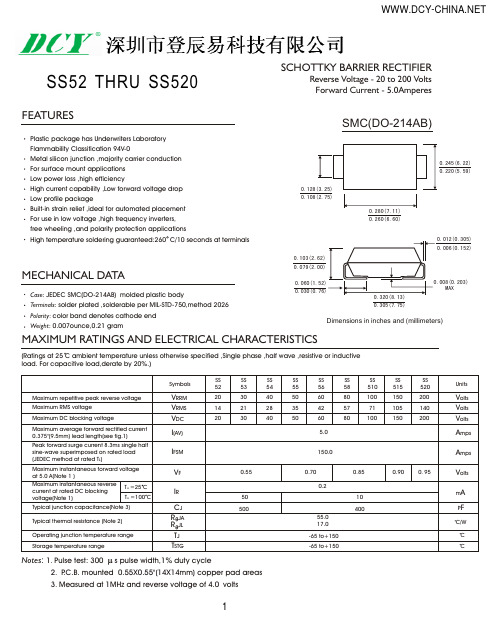
SS52 THRU SS520SCHOTTKY BARRIER RECTIFIERReverse Voltage - 20 to 200 Volts Forward Current - 5.0AmperesFEATURESMECHANICAL DATAMAXIMUM RATINGS AND ELECTRICAL CHARACTERISTICSPlastic package has Underwriters Laboratory Flammability Classification 94V-0Metal silicon junction ,majority carrier conduction For surface mount applications Low power loss ,high efficiencyHigh current capability ,Low forward voltage drop Low profile packageBuilt-in strain relief ,ideal for automated placement For use in low voltage ,high frequency inverters,free wheeling ,and polarity protection applicationsHigh temperature soldering guaranteed:260 C/10 seconds at terminalsCase : JEDEC SMC(DO-214AB) molded plastic bodyT erminals : solder plated ,solderable per MIL-STD-750,method 2026Polarity : color band denotes cathode end Weight : 0.007ounce,0.21 gram(Ratings at 25 C ambient temperature unless otherwise specified ,Single phase ,half wave ,resistive or inductive load. For capacitive load,derate by 20%.)Dimensions in inches and (millimeters)SMC(DO-214AB)0.260(6.60)0.305(7.75)Notes : 1.Pulse test: 300 s pulse width,1% duty cycle2. P .C.B. mounted 0.55X0.55"(14X14mm) copper pad areas3.Measured at 1MHz and reverse voltage of4.0 volts10.010.0010.0110.110200.11030609012050101101000.20.40.60.81.01.61.41.2FIG.1-FORWARD CURRENT DERATING CURVEFIG.2-MAXIMUM NON-REPETITIVE PEAK FORWARD SURGE CURRENTFIG.3-TYPICAL INSTANTANEOUS FORWARD CHARACTERISTICSFIG.4-TYPICAL REVERSE CHARACTERISTICSI N S T A N T A N E O U S F O R W A R D C U R R E N T ( A M P E R E S )I N S T A N T A N E O U S R E V E R S E C U R R E N T (m A )P E A K F O R W A R D S U R G EC U R R E N T (A MP E R E S )INSTANTANEOUS FORWARD VOLTAGE (VOLTS)REVERSE VOLTAGE. VOLTS T , PULSE DURATION ,sec.PERCENT OF RATED PEAK REVERSE VOLTAGE%NUMBER OF CYCLES AT 60Hz101100.10.10.011101001001000100FIG.5-TYPICAL JUNCTION CAPACITANCEFIG.6-TYPICAL TRANSIENT THERMAL IMPEDANCEJ U N C T I O N C A P A C I T A N C E (p F )T R A N S I E N T T H E R M A L I M P E D A N C E , C / W204060801001201502.03.04.05.01.0A V E R A G E F O R W A R D C U R R E N T A M P E R E SLEAD TEMPERATURE ( C)2SS52 THRU SS520SCHOTTKY BARRIER RECTIFIERReverse Voltage - 20 to 200 Volts Forward Current - 5.0Amperes。
FH1N5820~5822(DO-214AB)肖特基二极管规格书

ቆᄂऔSchottky DiodeSchottky Diode ቆᄂऔFH1N5820~58221DESCRIPTION & FEATURES 概述及特點 DO-214AB(SMC)Low leakage current 低反向電流For use in low voltage, high frequency inverters free wheeling, and polarity protection applications. 應用於低壓高頻保護電路PIN ASSIGNMENT 引腳說明PIN NUMBER 引腳序號PIN NAME 管腳符號 DO-214AB(SMC) FUNCTION 功能 A 1 Anode C 2 CathodeMaximum Ratings &Thermal Characteristics * (T a =25℃) 最大額定值及熱特性CHARACTERISTIC 特性參數 Symbol 符號Value 數值 Unit 單位Average Rectified Current 整流電流 I F(AV) 3.0ASurge Forward Current at t <1s and T A =25℃正向浪湧電流I FSM 80 A Total Device Dissipation 耗散功率 P D 1.25 W Derate above 25℃ 超25℃時P D 降幅 12.5 mW/℃ Thermal Resistance Junction to ambient air 熱阻 R ΘJA20℃/mW Junction and Storage Temperature 結溫和儲存溫度T J ,T STG -65~150 ℃*These ratings are limiting values above which the serviceability of any semiconductor device may beimpaired.ELECTRICAL CHARACTERISTICS 電特性(T A =25℃ unless otherwise noted 如無特殊說明,溫度為25℃)Value 數值 CHARACTERISTIC 特性參數Symbol 符號 1N5820 1N5821 1N5822 Unit單位 Maximum Repetitive Reverse Voltage最大反向電壓V RRM 20 30 40 VForward Voltage @1.0A正向電壓475 500 525Forward Voltage @3.0A正向電壓V FM850 900 950mVT A =25℃ 0.5 Reverse Current @rated V R反向電流 I RM T A =100℃ 20mATypical Junction capacitance 結電容 C J190 pF【南京南山半导体有限公司 — 风华高科贴片肖特基二极管选型资料】。
ASEMI SS24(DO-214AC SMA)肖特基二极管规格书
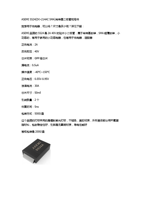
ASEMI SS24(DO-214AC SMA)肖特基二极管规格书
我想用于充电器,可以吗?尺寸是多少呢?详见下解:
ASEMI品牌的SS24是2A 40V的贴片小二极管,属于肖特基封装,SMA超薄封装,小功率的,常用于家用的小功率电器,也常用于充电器,适配器
正向电流:2A
反向耐压:40V
芯片材质:GPP硅芯片
漏电流:0.5uA
操作温度:-40℃~150℃
正向电压:0.55V-0.95V
浪涌电流:30A
芯片尺寸:50mil
引线数量:2个
恢复时间:5ns
包装方式:5000/盘
这个品牌的打标采用的是镭射激光打标,不褪色,黑胶材质,外形黑体部分用环氧塑脂材料,包封稳定性好,引脚是无氧铜材质,导电性能好
常规包装是2000/盘
尺寸如下:
规格书。
超快恢复二极管 ES2K SMB(DO-214AA)系列规格书推荐

CJ
25.0
Typical thermal resistance (NOTE 3)
RθJA
Operating junction and storage temperature range TJ T, STG
20.0 -50 to +150
Note:1.Reverse recovery condition IF=0.5A,IR=1.0A,Irr=0.25A 2.Measured at 1MHz and applied reverse voltage of 4.0V D.C. 3.Pulse test: Pulse width 200 sec, Duty cycle 2%
Cycles
Peak Forward Surge Current - Amperesversus Number Of Cycles At 60Hz - Cycles
Figure 5 New SMB Assembly
Round Lead Process
Figure 6 Reverse Recovery Time Characteristic And Test Circuit Diagram
FEATURES
CCLeoaamsdepFlMiareanette.FrSiianelis:ehMo/RordoldehersidnCgPoilnmafsoptrliimca.natti(oUNnLo) tFel1a)m("mPa"Sbuiliftfyix designates
MAX 2.95 2.25 .20 .51 1.40 2.32 5.69 4.57 3.94
NOTE
MECHANICAL DATA
Case: JEDEC DO-214AA molded plastic body over passivated chip Terminals: Solder plated, solderable per MIL-STD-750, Method 2026 Polarity: Color band denotes cathode end Mounting Position: Any Weight :0.005 ounce, 0.138 grams
S10M DO-214AB SMC 规格书推荐
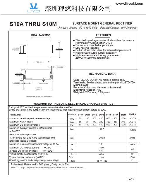
VRRM VRMS VDC
I(AV)
50 100 35 70 50 100
IFSM
rated load (JEDEC Method) Maximum instantaneous forward voltage at 10.0A Maximum DC reverse current TA=25 C at rated DC blocking voltage TA=100 C Typical junction capacitance (NOTE 1) Typical thermal resistance (NOTE 2) Operating junction and storage temperature range
MAXIMUM RATINGS AND ELECTRICAL CHARACTERISTICS
Ratings at 25 C ambient temperature unless otherwise specified. Single phase half-wave 60Hz,resistive or inductive load,for capacitive load current derate by 20%.
Figure 1 Typical Forward Characteristics
100
60 40
20 10 6
4
2 Amps 1
.6 .4
25qC
.2 .1 .06 .04
Figure 2 Forward Derating Curve
12
10
8
6 Amps
4
2 Single Phase, Half Wave 60Hz Resistive or Inductive Load
US1D DO-214AC SMA 规格书推荐
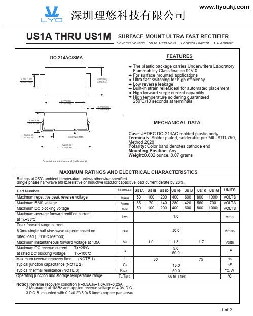
US1A THRU US1M
DO-214AC/SMA
SURFACE MOUNT ULTRA FAST RECTIFIER
Reverse Voltage - 50 to 1000 Volts Forward Current - 1.0 Ampere
FEATURES
The plastic package carries Underwriters Laboratory Flammability Classification 94V-0 For surface mounted applications Ultra fast switching for high efficiency Low reverse leakage Built-in strain relief,ideal for automated placement High forward surge current capability High temperature soldering guaranteed 250 C/10 seconds at terminals
1 of 2
RATINGS AND CHARACTERISTIC CURVES US1A THRU US1M
AVERAGE FORWARD RECTIFIED CURRENT, AMPERES PEAK FORWARD SURGE CURRENT, AMPERES
FIG. 1- FORWARD CURRENT DERATING CURVE
Dimensions in inches and (millimeters)
MAXIMUM RATINGS AND ELECTRICAL CHARACTERISTICS
Ratings at 25 C ambient temperature unless otherwise specified. Single phase half-wave 60Hz,resistive or inductive load,for capacitive load current derate by 20%. Part Number Maximum repetitive peak reverse voltage Maximum RMS voltage Maximum DC blocking voltage Maximum average forward rectified current at TL=55 C Peak forward surge current 8.3ms single half sine-wave superimposed on rated load (JEDEC Method) Maximum instantaneous forward voltage at 1.0A Maximum DC reverse current TA=25 C at rated DC blocking voltage TA=100 C Maximum reverse recovery time (NOTE 1) Typical junction capacitance (NOTE 2) Typical thermal resistance (NOTE 3) Operating junction and storage temperature range
S10J DO-214AB SMC 规格书推荐
200.0
1.2 10.0 100.0 60.0 10.0 -55 to +150
S10K
800 560 800
S10M
1000 700 1000
UNITS VOLTS VOLTS VOLTS
Amps
Amps
Volts µA pF C/W C
1 of 3
RATINGS AND CHARACTERISTIC CURVES S10A THRU S10M
VRRM VRMS VDC
I(AV)
50 100 35 70 50 100
IFSM
rated load (JEDEC Method) Maximum instantaneous forward voltage at 10.0A Maximum DC reverse current TA=25 C at rated DC blocking voltage TA=100 C Typical junction capacitance (NOTE 1) Typical thermal resistance (NOTE 2) Operating junction and storage temperature range
0.245(6.22) 0.220(5.59)
0.103(2.62) 0.079(2.06)
0.280(7.11) 0.260(6.60)
0.012(0.305) 0.006(0.152)
0.060(1.52) 0.030(0.76)
0.008(0.203)MAX. 0.320(8.13) 0.305(7.75)
MAXIMUM RATINGS AND ELECTRICAL CHARACTERISTICS
通用二极管S2A-S2M DO-214AC SMA系列规格书推荐
0.060(1.52) 0.030(0.76)
0.008(0.203)MAX.
0.208(5.28) 0.188(4.80)
Dimensions in inches and (millimeters)
MAXIMUM RATINGS AND ELECTRICAL CHARACTERISTICS
Ratings at 25 C ambient temperature unless otherwise specified. Single phase half-wave 60Hz,resistive or inductive load,for capacitive load current derate by 20%. Part Number Maximum repetitive peak reverse voltage Maximum RMS voltage Maximum DC blocking voltage Maximum average forward rectified current at TL=110 C Peak forward surge current 8.3ms single half sine-wave superimposed on rated load (JEDEC Method) Maximum instantaneous forward voltage at 2.0A Maximum DC reverse current TA=25 C at rated DC blocking voltage TA=100 C Typical junction capacitance (NOTE 1) Typical thermal resistance (NOTE 2) Operating junction and storage temperature range
SS34 SMC(DO-214AB)肖特基二极管原厂DCY品牌推荐
SS32 THRU SS36SURFACE MOUNT SCHOTTKY BARRIER RECTIFIERReverse Voltage -20 to 60 Volts Forward Current -3.0 AmperesFEATURES♦ Plastic package has Underwriters Laboratory Flammability Classification 94V-0♦ For surface mount applications ♦ Low profile package♦ Built-in strain relief, ideal for automated placement ♦ Easy pick and place ♦ Metal silicon junction, majority carrier conduction♦ Low power loss, high efficiency♦ High current capability, low forward voltage drop♦ For use in low voltage, high frequency inverters, free wheeling, and polarity protection applications ♦ High temperature soldering:250°C/10 seconds at terminalsMECHANICAL DATACase:JEDEC DO-214AB molded plastic bodyTerminals:Solder plated, solderable per MIL-STD-750,Method 2026Polarity:Color band denotes cathode end Weight:0.007 ounce 0.25 gramMAXIMUM RATINGS AND ELECTRICAL CHARACTERISTICSRatings at 25°C ambient temperature unless otherwise specified.SYMBOLS SS32SS33SS34SS35SS36UNITSDevice marking codeS2S3S4S5S6Maximum repetitive peak reverse voltage V RRM 2030405060Volts Maximum RMS voltage V RMS 1421283542Volts Maximum DC blocking voltageV DC 2030405060Volts Maximum average forward rectified current at T L (SEE FIG.1) (NOTE 2)I (AV) 3.0Amps Peak forward surge current8.3ms single half sine-wave superimposed on I FSM100.0Ampsrated load (JEDEC Method)Maximum instantaneous forward voltage at 3.0A(NOTE 1)V F 0.500.75Volts Maximum DC reverse current (NOTE 1)T A =25°C 0.5at rated DC blocking voltage T A =100°C I R 20.010.0mA Typical thermal resistance (NOTE 2)R ΘJA 55.0R ΘJL 17.0°C/WOperating junction temperature range T J -55 to +125-55 to +150°C Storage temperature rangeT STG-55 to +150°CNOTES:(1) Pulse test:300µs pulse width, 1% duty cycle(2) P .C.B.mounted 0.55 x 0.55”(14 x 14mm) copper pad areasDO-214ABDimensions in inches and (millimeters)。
肖特基二极管 SK310 DO-214AB SMC系列规格书推荐
Amps Volts mA pF C/W C C
Note:1.Measured at 1MHz and applied reverse voltage of 4.0V D.C. 2.P.C.B. mounted with 0.2x0.2”(5.0x5.0mm) copper pad areas
1 of 2
10.0
10 TJ=100 C 1
1
TJ=75 C 0.1
0.1
SK32-SK34 SK35-SK36 SK38-SK3150 SK3200
0.01 TJ=25 C
0.001
0
20
40
60
80
100
0.01
PERCENT OF PEAK REVERSE VOLTAGE,%
0 0.2 0.4 0.6 0.8 1.0 1.2 1.4 1.6
Dimensions in inches and (millimeters)
MAXIMUM RATINGS AND ELECTRICAL CHARACTERISTICS
Ratings at 25 C ambient temperature unless otherwise specified. Single phase half-wave 60Hz,resistive or inductive load,for capacitive load current derate by 20%. Part Number Maximum repetitive peak reverse voltage Maximum RMS voltage Maximum DC blocking voltage Maximum average forward rectified current at TL(see fig.1) Peak forward surge current 8.3ms single half sine-wave superimposed on rated load (JEDEC Method) Maximum instantaneous forward voltage at 3.0A Maximum DC reverse current TA=25 C at rated DC blocking voltage TA=100 C Typical junction capacitance (NOTE 1) Typical thermal resistance (NOTE 2) Operating junction temperature range Storage temperature range
- 1、下载文档前请自行甄别文档内容的完整性,平台不提供额外的编辑、内容补充、找答案等附加服务。
- 2、"仅部分预览"的文档,不可在线预览部分如存在完整性等问题,可反馈申请退款(可完整预览的文档不适用该条件!)。
- 3、如文档侵犯您的权益,请联系客服反馈,我们会尽快为您处理(人工客服工作时间:9:00-18:30)。
FIG. 2-MAXIMUM NON-REPETITIVE PEAK FORWARD SURGE CURRENT
100
2.4
Single Phase Half Wave 60Hz Resistive or inductive Load
FIG. 5-TYPICAL JUNCTION CAPACITANCE
TRANSIENT THERMAL IMPEDANCE, C/W
INSTANTANEOUS FORWARD VOLEAGE, VOLTS
FIG. 6-TYPICAL TRANSIENT THERMAL IMPEDANCE
100
JUNCTION CAPACITANCE, pF
80
1.8
60
1.2
40
0.6
SK32-SK36 SK38-SK3200
20
8.3ms SINGLE HALF SINE-WAVE (JEDEC Method)
0 0 25 50 75 100 125 150 175
0
1
10
100
AMBIENT TEMPERATURE, C
NUMBER OF CYCLES AT 60 Hz
200 150 200
VOLTS VOLTS VOLTS Amps
IFSM VF IR CJ RθJA TJ, TSTG 500 0.55 20
100.0 0.70 0.5 10 300 55.0 -50 to +125 -50 to +150 -50 to +150 0.85 0.95 0.2 2.0
10.0
10 TJ=100 C 1
1
TJ=75 C 0.1
0.1
SK32-SK34 SK35-SK36 SK38-SK3150 SK3200
0.01 TJ=25 C
0.001
0
20
40
60
80
100
0.01
PERCENT OF PEAK REVERSE VOLTAGE,%
0 0.2 0.4 0.6 0.8 1.0 1.2 1.4 1.6
Dimensions in inches and (millimeters)
MAXIMUM RATINGS AND ELECTRICAL CHARACTERISTICS
Ratings at 25 C ambient temperature unless otherwise specified. Single phase half-wave 60Hz,resistive or inductive load,for capacitive load current derate by 20%. Part Number Maximum repetitive peak reverse voltage Maximum RMS voltage Maximum DC blocking voltage Maximum average forward rectified current at TL(see fig.1) Peak forward surge current 8.3ms single half sine-wave superimposed on rated load (JEDEC Method) Maximum instantaneous forward voltage at 3.0A Maximum DC reverse current TA=25 C at rated DC blocking voltage TA=100 C Typical junction capacitance (NOTE 1) Typical thermal resistance (NOTE 2) Operating junction temperature range Storage temperature range
2000 1000 TJ=25 C
10
100
1
SK32-SK34 SK35-SK3200
0.1 0.01 0.1 1 10 100
10 0.1 1.0 10 100
REVERSE VOLTAGE,VOLTS
t,PULSE DURATION,sec.
2 of 2
Amps Volts mA pF C/W C C
Note:1.Measured at 1MHz and applied reverse voltage of 4.0V D.C. 2.P.C.B. mounted with 0.2x0.2”(5.0x5.0mm) copper 0(1.52) 0.030(0.76)
0.320(8.13) 0.305(7.75)
Case: JEDEC DO-214AB molded plastic body Terminals: Solder plated, solderable per MIL-STD-750, Method 2026 Polarity: Color band denotes cathode end Mounting Position: Any Weight:0.007 ounce, 0.25grams
SYMBOLS SK32 SK33
SK34 SK35 SK36
SK38 SK310 SK3150 SK3200 UNITS
VRRM VRMS VDC I(AV)
20 14 20
30 21 30
40 28 40
50 35 50
60 42 60 3.0
80 56 80
100 70 100
150 105 150
深圳理悠科技有限公司
AVERAGE FORWARD RECTIFIED CURRENT, AMPERES
FIG. 1- FORWARD CURRENT DERATING CURVE
3.0
RATINGS AND CHARACTERISTIC CURVES SK32 THRU SK3200
FEATURES
The plastic package carries Underwriters Laboratory Flammability Classification 94V-0 For surface mounted applications Low reverse leakage Built-in strain relief,ideal for automated placement High forward surge current capability High temperature soldering guaranteed: 250 C/10 seconds at terminals
0.126 (3.20) 0.114 (2.90)
0.245(6.22) 0.220(5.59)
0.280(7.11) 0.260(6.60) 0.012(0.305) 0.006(0.152)
0.103(2.62) 0.079(2.06)
MECHANICAL DATA
0.008(0.203)MAX.
50
TJ=25 C
INSTANTANEOUS REVERSE CURRENT, MILLIAMPERES
FIG. 3-TYPICAL INSTANTANEOUS FORWARD CHARACTERISTICS
FIG. 4-TYPICAL REVERSE CHARACTERISTICS
100
INSTANTANEOUS FORWARD CURRENT,AMPERES
深圳理悠科技有限公司
SK32 THRU SK3200
DO-214AB/SMC
Reverse Voltage - 20 to 200 Volts
SURFACE MOUNT SCHOTTKY BARRIER RECTIFIER
Forward Current - 3.0 Amperes