MasterCAM9.1车床后处理MPLFAN.PST的修改方法
mastercam后处理讲解
3、删除第四轴数据“A0.”,以适应三轴加工中心:
单击按钮,系统弹出查找对话框,输入“Rotary Axis”,单击按钮,查找结果所在行为:
164. Enable Rotary Axis button? y
8、输出普通及啄式钻孔循环指令:
单击按钮,系统弹出查找对话框,输入“usecandrill”,单击 按钮,查找结果相关行为:
usecandrill : no #Use canned cycle for drill
usecanpeck : no #Use canned cycle for Peck
将其修改为:
pbld, n, scoolant, e
# pbld, n, *sg28ref, "X0.", "Y0.", protretinc, e
输出的NC文件修改前对应位置指令为:
N116G91G28Z0.M9
修改后变为:
N116M9
PST文件中另有两个类似位置,如使用G92指令确定工件坐标,可对其适当修改。加工结束后,机床各轴不回参考点,便于手动换刀时节省时间。
⑵FANUC.PST后处理文件针对的是4轴加工中心,而目前使用量最大的是3轴加工中心,多出了第4轴数据“A0.”。
⑶不带刀库的数控铣使用时要去掉刀具号、换刀指令、回参考点动作。
⑷部分控制器不接受NC文件中的注释行。
⑸删除行号使NC文件进一步缩小。
⑹调整下刀点坐标值位置,以便于在断刀时对NC文件进行修改。
force_wcs : no #Force WCS output at every toolchange?
MasterCAM9.1车床后处理MPLFAN.PST的修改方法

A 程式是自带后处理出的,B 程式是改后的后处理出的。
本人并非专业编程人员,对编程只是知道些皮毛。
同事叫我帮忙修改一下MasterCAM9.1的后处理,因为每次都要手工修改,很麻烦,还怕出错。
在网上找了好久都找不到关于MasterCAM 车床后处理的修改方法,只好自己慢慢研究……最终还是改好了,能正常使用。
但我毕竟不是专业人氏,也不知会不会出现意外的情况,希望懂的人可以指正。
声明:此后处理适用MasterCAM 9.1,其它版本请自行研究。
如何要使用此后处理,请务必核对程式!凡使用此后处理一切后果自负!(经反馈,两段程式合并一起处理时,会出现换刀指令!如不用刀库的必须注意!)找到车床的后处理文件MPLFAN.PST (位于Mcam9\Lathe\Posts\),复制一份出来放在同目录,改好自己喜欢的名字,打开修改。
以下是修改记录。
(黄色底纹是修改过的,注意对比源文件)force_wcs : no #删除程式中的G54,默认是yes 。
#去除程式中的M08、M09(冷却液开关)#fstrsel sm09 coolant scoolant#程序名,日期,时间等% O0000 G21(PROGRAM NAME - 111 DA TE=DD-MM-YY - 21-07-15 TIME=HH:MM - 10:00 ) (TOOL - 2 OFFSET - 2)(OD ROUGH LEFT - 80 DEG . INSERT - CNMG 12 04 08) G0 T0202 G97 S55 M03G0 G54 X-1.461 Z29.597 M9 G50 S55 G96 S295G99 G1 Z31.597 F.2 X-68.261 Z34.519G2 X-68.4 Z34.522 R.8 X-70. Z33.722 R.8 G1 Z2.922X-67.172 Z1.508 G28 U0. W0. M05 T0200 M30 %%(-111 .NC - 05-08-15 ) G0 X-1.461 Z29.597 S55 M03G99 G1 Z31.597 F.2 X-68.261 Z34.519G2 X-68.4 Z34.522 R.8 X-70. Z33.722 R.8 G1 Z2.922X-67.172 Z1.508 M30 %A B# *progno, e #去除程序名# pbld, n, *smetric, e #去除G21"(-", progname,".NC", "- ", date, ")", e #程度名和日期,随意更改#删除程式中的刀具和刀片描述# ptoolcomment# comment#删除程式中的“G0 T0202(刀具号)”# pbld, n, *sgcode, *toolno, e#以下两段调换顺序,可以调换“G0快速定位”和“主轴转动”的顺序。
mastercam9.1后处理
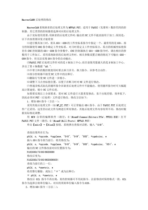
MasterCAM9后处理的修改MasterCAM系统缺省的后处理文件为MPFAN.PST,适用于FANUC(发那科)数控代码的控制器。
其它类型的控制器需选择对应的后处理文件。
由于实际使用需要,用缺省的后处理文件时,输出的NC文件不能直接用于加工。
原因是:以下内容需要回复才能看到⑴进行模具加工时,需从G54~G59的工件坐标系指令中指定一个,最常用的是G54。
部分控制器使用G92指令确定工件坐标系。
对刀时需定义工件坐标原点,原点的机械坐标值保存在CNC控制器的G54~G59指令参数中。
CNC控制器执行G54~G59指令时,调出相应的参数用于工件加工。
采用系统缺省的后处理文件时,相关参数设置正确的情况下可输出G55~G59指令,但无法实现G54指令的自动输出。
⑵FANUC.PST后处理文件针对的是4轴加工中心,而目前使用量最大的是3轴加工中心,多出了第4轴数据“A0.”。
⑶不带刀库的数控铣使用时要去掉刀具号、换刀指令、回参考点动作。
⑷部分控制器不接受NC文件中的注释行。
⑸删除行号使NC文件进一步缩小。
⑹调整下刀点坐标值位置,以便于在断刀时对NC文件进行修改。
⑺普通及啄式钻孔的循环指令在缺省后处理文件中不能输出。
使用循环指令时可大幅提高计算速度,缩小NC文件长度。
如果要实现以上全部要求,需对NC文件进行大量重复修改,易于出现差错,效率低下,因此必须对PST(后处理)文件进行修改。
修改方法如下:1、增加G54指令(方法一):采用其他后处理文件(如MP_EZ.PST)可正常输出G54指令。
由于FANUC.PST后处理文件广泛采用,这里仍以此文件为例进行所有修改。
其他后处理文件内容有所不同,修改时根据实际情况调整。
用MC9自带的编辑软件(路径:C:\Mcam9\Common\Editors\Pfe\ PFE32.EXE)打开FANUC.PST文件(路径:C:\Mcam9\Mill\Posts\ MPFAN.PST)单击【edit】→【find】按钮,系统弹出查找对话框,输入“G49”。
MasterCAM后处理文件的修改

, a4 c G4 X. K5 k) |; t, W三维网技术论坛选择【File】>【Edit】>【PST】命令,系统弹出读文件窗口,选择Mpfan.PST文件,系统弹出如下图所示编辑器。 三维,cad,机械,技术,汽车,catia,pro/e,ug,inventor,solidedge,solidworks,caxa,时空,镇江# ~, I1 Q& r$ E( s% e6 ]4 i+ j! M
6 ]' n# @( L0 ~2 M7 Z% z三维,cad,机械,技术,汽车,catia,pro/e,ug,inventor,solidedge,solidworks,caxa,时5 z) l: R* }; m3 Y$ @2 s7 i) k三维网技术论坛# pbld, n, *smetric, e 三维,cad,机械,技术,汽车,catia,pro/e,ug,inventor,solidedge,solidworks,caxa,时空,镇江. C* Y6 I/ q& v6 E, E( c
: P7 w' W q8 z- V4 b1 n: u( |三维|cad|机械|汽车|技术|catia|pro/e|ug|inventor|solidedge|solidworks|caxaN102G0G17G40G49G80G90 三维网技术论坛3 u9 q; h' t8 M" h
MasterCAM9后处理程序的优化.
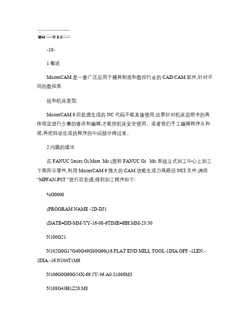
-10-1概述MasterCAM 是一套广泛应用于模具制造和数控行业的CAD/CAM 软件,针对不同的数控系统和机床类型,MasterCAM 9后处理生成的NC 代码不能直接使用,还要针对机床说明书的具体规定进行少量的修改和编辑,才能供机床安全使用。
或者我们手工编辑程序头和尾,再把自动生成的程序的中间部分拷过来。
2问题的提出在FANUC Series Oi Mate_Mc (简称FANUC Oi _Mc 系统立式加工中心上加工下图所示零件,利用MasterCAM 9强大的CAM 功能生成刀具路径NCI 文件,调用“MPFAN.PST ”进行后处理,得到加工程序如下:%O0000(PROGRAM NAME -2D-DJ1(DATE=DD-MM-YY-16-08-6TIME=HH:MM-23:30N100G21N102G0G17G40G49G80G90(16.FLAT END MILL TOOL-1DIA.OFF.-1LEN.-1DIA.-16.N104T1M6N106G0G90G54X-69.5Y-36.A0.S1000M3N108G43H1Z20.M8N110Z5.N112G1Z-7.F50.N114X-64.5N116G3X-48.5Y-20.R16.N118G1Y-7.5……N506G1X-40.N508G2X-44.Y7.5R4.N510G1Y13.77N512G3X-52.Y21.77R8.N514G1X-54.5N516G0Z20.N518M5N520G91G28Z0.M9N522G28X0.Y0.A0.N524M30%NC 代码存在的问题有:2.1带括号部分的程序名、日期时间、刀具说明,对有的数控系统不能承认,如:华中数控、广州数控。
2.2G21、G17为缺省值,无需写出。
2.3存在换刀指令T1M6及刀具长度正补偿指令G43H1,容易造成撞刀事故。
2.4立式加工中心因没有安装第4轴,存在工作台绕X 轴旋转的指令A0,所有数控系统的三轴加工中心或数控铣床都不能承认,否则系统报警。
最新MasterCAM9后处理的修改

M a s t e r C A M9后处理的修改MasterCAM9后处理的修改MasterCAM系统缺省的后处理文件为MPFAN.PST,适用于FANUC(发那科)数控代码的控制器。
其它类型的控制器需选择对应的后处理文件。
由于实际使用需要,用缺省的后处理文件时,输出的NC文件不能直接用于加工。
原因是:以下内容需要回复才能看到⑴进行模具加工时,需从G54~G59的工件坐标系指令中指定一个,最常用的是G54。
部分控制器使用G92指令确定工件坐标系。
对刀时需定义工件坐标原点,原点的机械坐标值保存在CNC控制器的G54~G59指令参数中。
CNC 控制器执行G54~G59指令时,调出相应的参数用于工件加工。
采用系统缺省的后处理文件时,相关参数设置正确的情况下可输出G55~G59指令,但无法实现G54指令的自动输出。
⑵FANUC.PST后处理文件针对的是4轴加工中心,而目前使用量最大的是3轴加工中心,多出了第4轴数据“A0.”。
⑶不带刀库的数控铣使用时要去掉刀具号、换刀指令、回参考点动作。
⑷部分控制器不接受NC文件中的注释行。
⑸删除行号使NC文件进一步缩小。
⑹调整下刀点坐标值位置,以便于在断刀时对NC文件进行修改。
⑺普通及啄式钻孔的循环指令在缺省后处理文件中不能输出。
使用循环指令时可大幅提高计算速度,缩小NC文件长度。
如果要实现以上全部要求,需对NC文件进行大量重复修改,易于出现差错,效率低下,因此必须对PST(后处理)文件进行修改。
修改方法如下:1、增加G54指令(方法一):采用其他后处理文件(如MP_EZ.PST)可正常输出G54指令。
由于FANUC.PST后处理文件广泛采用,这里仍以此文件为例进行所有修改。
其他后处理文件内容有所不同,修改时根据实际情况调整。
用MC9自带的编辑软件(路径:C:\Mcam9\Common\Editors\Pfe\PFE32.EXE)打开FANUC.PST文件(路径:C:\Mcam9\Mill\Posts\ MPFAN.PST)单击【edit】→【find】按钮,系统弹出查找对话框,输入“G49”。
Mastercam9

Mastercam9.1后处理设置Mastercam9.1是一款广泛应用于机械制造行业的计算机辅助设计和制造软件。
在使用Mastercam9.1进行数控编程时,后处理设置是非常重要的一步。
本文将介绍Mastercam9.1后处理设置的步骤和注意事项。
步骤以下是设置Mastercam9.1后处理的步骤:1.打开Mastercam9.1软件,并选择需要进行后处理设置的机床类型。
2.进入后处理设置界面,选择“工具”菜单下的“后处理工具”。
3.在后处理工具界面中,选择左侧的“设置管理器”。
4.在设置管理器中,将光标定位到当前使用的后处理器上,并点击右键选择“编辑”。
5.进入后处理器编辑界面后,可以对后处理器进行各种设置。
6.首先,需要设置后处理的输出文件路径。
点击“文件”菜单下的“设置文件名”选项,设置输出文件的路径和文件名。
7.接下来,根据具体的机床和加工需求,可以进行一些其他的设置,例如刀具补偿、刀具半径补偿、进给速度等。
8.对于一些特殊的加工工艺,还可以在后处理器编辑界面中添加自定义的代码段,以满足特定的加工需求。
9.设置完所有的参数后,点击保存并关闭后处理器编辑界面。
10.返回到设置管理器界面,可以将当前设置的后处理器设为默认后处理器,以便在以后的操作中直接使用。
11.完成所有的设置后,可以关闭后处理工具界面,开始进行数控编程。
注意事项在进行Mastercam9.1后处理设置时,需要注意以下几点:1.不同机床类型所需的后处理设置可能有所不同,在选择后处理器时要根据实际的机床类型进行选择。
2.在进行后处理设置之前,要先了解机床的技术参数和加工要求,确保后处理器的设置与之相符。
3.后处理的输出文件路径要设置在合适的位置,方便后续的操作和查找。
4.在进行一些高级的设置时,要小心操作,确保设置的正确性和安全性。
5.在使用自定义代码段时,要谨慎选择和添加代码,确保其适用性和正确性。
6.建议在进行后处理设置之前先做好程序的检查和验证,以减少出错的可能性。
MasterCAM9.1的刀具清单功能(可编辑修改word版)

MasterCAM9.1 后处理自动生成刀具清单,使用方法:将下面的内容复制到记事本内,并将其更名为Mpfan.pst,pst 为后缀,再将该文件拷贝至MasterCAM9.1 的安装目录C:\Mcam9\Mill\Posts,覆盖原文件,然后启动软件,可以在NC 程序开头生成刀具清单。
经典版本,绝对好用!# Post Name : MPFAN# Product : MILL# Machine Name : FANUC# Control Name : 6M# Description : GENERIC FANUC 6M STYLE POST# Associated Post :# Mill/Turn : NO# 4-axis/Axis subs. : NO# 5-axis : NO# Executable : MP 4.03## ************************************************************************ # *----------------------------------------------------------------------*# * POST PROCESSOR INTENDED FOR VERSION 6 BETA TESTING *# * * # * D O N O T D I S T R I B U T E ! ! ! *# * ------------------------------------------------------------------------ *# ************************************************************************ ###| REVISION LOG |## Programmers Note:# CNC 8/15/2005 - grt - Updated for Mill Version 6###| FEATURES: |## Users Note:## Following Misc_Reals & Misc_Integers are used:## mi1 - Work coordinate system# 0 = Reference return is generated and G92 with the# X, Y and Z home positions at file head.# 1 thru 3 = Reference return is generated and G92 with the# X, Y and Z home positions at each tool.# 4 thru 9 = The WCS of G54 thru G59 respectively at each tool.## Options / Usage:# It is recommended to start and end cutter compensation on a linear move.# Rotary axis assumes a "Z" plunge at feed into part, position of the# substituted axis at absolute zero position and the retraction from path# by the post call to the G28 machine Z home position.## DEBUG/PROGRAM SWITCHES, debugging and program switches#bug1 : 1 # 1 = Output post to screen, 2 = output leader to screenbug2 : 0 # Append postline labels, non-zero is column position?bug3 : 0 # Append whatline no. to each NC line?bug4 : 0 # Append NCI line no. to each NC line?whatno : yes # Do not perform whatline branches?strtool_v7 : 2 #Use Version 7 toolname, 1= path components, 2=string get_1004 : 1 #Find gcode 1004 with getnextop?rpd_typ_v7 : 1 #Use Version 7 style contour flags?arcoutput : 2 # 0 = IJK, 1 = R no sign, 2 = R signed neg. over 180 breakarcs : 0 #Break arcs, 0 = no, 1 = quadrants, 2 = 180deg. max arcsstagetool : 0 # 0 = Do not pre-stage tools, 1 = Stage toolsuse_gear : no # Set to yes to output gear range codes## FORMAT STATEMENTS - n=nonmodal, l=leading, t=trailing, i=inc, d=delta #fs 1 0.3 #Decimal, absolute, 4 placefs 2 0.4d #Decimal, deltafs 3 1 0 #Integer, not leadingfs 4 2 0l #Integer, two leadingfs 5 3 0l #Integer, three leadingfs 6 4 0l #Integer, four leadingfs 7 0.1 #Decimal, absolute, 1 placefs 8 0.2 #Decimal, absolute, 2 placefs 9 0.3 #Decimal, absolute, 3 placefs 10 0 4t #No decimal, absolute, four trailingfs 11 0.4t #Decimal, absolute, four trailing## FORMAT ASSIGNMENTS## Axis output formats - Linear#fmt X 1 x # X axis positionfmt Y 1 y # Y axis positionfmt Z 1 z # Z axis positionfmt X 1 xr # X rapid position from tool change fmt Y 1 yr # Y rapid position from tool change fmt Z 1 zr # Z rapid position from tool change fmt X 1 xh # X home positionfmt Y 1 yh # Y home positionfmt Z 1 zh # Z home position## Axis output formats - Circular#fmt I 2 i # Arc center description in Xfmt J 2 j # Arc center description in Yfmt K 2 k # Arc center description in Zfmt R 1 arcrad # Arc Radiusfmt R- 1 arcradm # Arc Radius over 180 degree sweep## Axis output formats - Rotary substitution#fmt A 9 xs # Linear to rotary calculation of X fmt B 9 ys # Linear to rotary calculation of Y## Program & Sequence number format#fmt O 6 progno # Program numberfmt N 3 n # Sequence nos.## Tool format#fmt T 3 t # Tool Nofmt T 3 first_tool# First Tool Used (bldnxtool: yes)fmt T 3 next_tool # Next Tool Used (bldnxtool: yes) fmt D 3 tloffno # Diameter Offset Nofmt H 3 tlngno # Length Offset Nofmt "T" 1 tnote # Note formatfmt "D-" 1 toffnote # Note formatfmt "H-" 1 tlngnote # Note formatfmt "Dia-" 2 tldia # Note format## Spindle Speeds & Feedrate output formats#fmt S 6 speed # Spindle Speedfmt F 8 fr # Feedratefmt F 7 frdeg # Feedrate for rotaryfmt M 3 gear # Gear range## Drill variable formats#fmt G 3 drillref # Initial / Reference Toggle (G98/G99)fmt P 10 dwell # Dwellfmt Z 1 initht # Initial Heightfmt R 1 refht # Reference Heightfmt Z 1 depth # Depthfmt Q 2 peck1 # First peck increment (positive)fmt 1 peck2 # Second or last peck (positive)fmt 1 peckclr # Safety distancefmt 1 retr # Retract heightfmt F 8 frplunge # Plunge feedrate in drill cycles## Miscellaneous output formats#fmt M 5 ssrange # Spindle Speed Rangefmt C 4 coolant # Coolant## INITIALIZE - initialize system variables and define user variables#qtoolpln : no # MP386 - Enable tool plane optionqtoolopt : no # MP386 - Enable tool optimizationarctype : 2 # Arc center 1=abs, 2=St-Ctr, 3=Ctr-St, 4=unsigned inc.do_full_arc : 0 #Allow full circle output? 0=no, 1=yeshelix_arc : 0 #Support helix arc output, 0=no, 1=all planes, 2=XY plane only bldnxtool : yes # Build next tool tableldrcode : 65 # Leader character dec. equiv. (fleader outputs code) ncldr : 20 # No. of leader characters (fleader outputs code) nobrk : no # Omit breakup of x/y & z rapid movesomitcrlf : no # Omit CR/LFomitrefht : no # Don't use reference height on first non-canned Z move omitseq : yes # Omit sequence no.omitz : no # Omit first Z movement for non-canned-cycles progname : 1 # Use uppercase for program namescalex : 1.0 # Scaling of .NCI at input - x,y,z,i,j,kscaley : 1.0 # Scaling of .NCI at input - x,y,z,i,j,kscalez : 1.0 # Scaling of .NCI at input - x,y,z,i,j,kseqmax : 9999 # Max. sequence no.skipmotest: no # Skip motion test in linearspaces : 1 # No. of spaces to add between fieldstooltable : 1 # Read for tool table and pwrttabsswp : 0 # Absolute sweepdrlgsel : -1 # Drill Select Initializemaxfrdeg : 9999 # Limit for feed in deg/minabsinc : 0 # Absolute/Incremental toggle for modalitytcnt : 0 # Count the number of tool changesadelta : 0 # Calculation for deg/minldelta : 0 # Calculation for deg/minzdelta : 0 # Calculation for deg/minalzdelta : 0 # Calculation for deg/minfrdelta : 0 # Calculation for deg/minfrdegcalc : 0 # Calculation for deg/mincircum : 0 # Calculation for deg/minrotstrt : 1 # Flag for first rotary positionnewglobal : 1 # Error Check (Leave this variable set to 1)## FORMULAS - global formulas#ssrange = mi3 # Gear Range Selectspeed = abs ( ss ) # Absolute spindle speedarcradm = arcrad # Negative arcradspdlsel = fsg3(ss) # Spindle on selector based on pos. or neg. ss## CANNED CYCLES - select long or short code#usecandrill : yes # Use canned cycle for drillusecanpeck : yes # Use canned cycle for Peckusecanchip : yes # Use canned cycle for Chip Breakusecantap : yes # Use canned cycle for Tapusecanbore1 : yes # Use canned cycle for Bore1usecanbore2 : yes # Use canned cycle for Bore2usecanmisc1 : yes # Use canned cycle for Misc1usecanmisc2 : yes # Use canned cycle for Misc2## Lookup table definitions - for math functions FLOOK and FRANGE #flktbl 1 3 # Lookup table definitions - table no. - no. entries40 1000 # Low gear range41 2500 # Med gear range42 5000 # Hi gear range## Strings - String labels must start with 's' - they are not pre-assigned ##Select operation notesop00 NULL # String definitionsop01 END-MIll # " "sop02 END-MIll # " "sop03 DRIll # " "sop04 END-MIll # " "sop05 S-MILL # " "sop06 2D-SWEPT.. # " "sop07 3D-SWEPT.. # " "sop08 REVOLVED.. # " "sop09 LOFT...... # " "sop10 COONS..... # " "sop11 TRIM ..... # " "sop12 FILLET.... # " "sop13 ROUGH..... # " "sop14 OP14...... # " "sop15 OP15...... # " "sopnote # Target stringfstrsel sop00 opcode sopnote## Select motion G codesg00 G0 # Linear movement at rapid feedratesg01 G1 # Linear movement at feedratesg02 G2 # Circular interpolation CWsg03 sgcode G3 # Circular interpolation CCW # Target stringfstrsel sg00 gcode sgcode## Select incremental or absolute G codesg90 G90 # Absolute G codesg91 G91 # Incremental G codesgabsinc # Target stringfstrsel sg90 absinc sgabsinc## Select spindle startsm04 M4 # Spindle reversesm05 M5 # Spindle offsm03 M3 # Spindle forwardspdlon # Target stringfstrsel sm04 spdlsel spdlon## Cutter compensation codescc0 "" # Cutter compensation state not changedsg40 G40 # Cancel cutter compensationsg41 G41 # Cutter compensation leftsg42 G42 # Cutter compensation rightsg140 G40 # Last linear move cancel cutter comp (see note)# Note: to cancel comp after last move, remove G40 stringsccomp # with sg140 and remove "#" at the postline call "pcancelcc" # Target stringfstrsel scc0 ccomp sccomp## Select work plane G codesg17 G17 # XY plane code sg19 G19 # XZ plane codesg18 G18 # YZ plane codesgplane # Target stringfstrsel sg17 plane sgplane## Work coordinate systemsg50 G92 # Work coordinate system G codesg51 G92 # " " " " "sg52 G92 # " " " " "sg53 G92 # " " " " "sg54 G54 # " " " " "sg55 G55 # " " " " "sg56 G56 # " " " " "sg57 G57 # " " " " "sg58 G58 # " " " " "sg59 G59 # " " " " "sgwcs # Target stringfstrsel sg50 mi1 sgwcs## Canned drill cycle string selectsg81 G81 # drill - no dwellsg81d G82 # drill - with dwellsg83 G83 # peck drill - no dwellsg83d G83 # peck drill - with dwellsg73 G73 # chip break - no dwellsg73d G73 # chip break - with dwellsg84 G84 # tap - no dwellsg84d G74 # tap - with dwell (selects left hand) sg85 G85 # bore #1 - no dwellsg85d G89 # bore #1 - with dwellsg86 G86 # bore #2 - no dwellsg86d G86 # bore #2 - with dwellsgm1 G81 # misc #1 - no dwellsgm1d G82 # misc #1 - with dwellsgm2 G81 # misc #2 - no dwellsgm2d G82 # misc #2 - with dwellsgdrill # Target stringdrlgsel = drillcyc * 2 + fsg2 ( dwell ) # 16 possible combinations:# drillcyc = 0..7# dwell = 0 or non-zero (2 states) fstrsel sg81 drlgsel sgdrill## Generate 'sgear' stringsgear0 M** # auto gear rangesgear1 M41 # Low gear rangesgear2 M42 # Med gear rangesgear3 M43 # High gear range - selected in parameters by mi3sgearfstrsel sgear0 gear sgear## POSTLINES, USER-DEFINED - Postline labels start with 'p'.# End a line with ',' to continue on the next line.# End a line with ', e' to generate carriage return and linefeed.## Program general output control, user defined#pinit # Initialize Varsprv_fr = 999.999prv_frdeg = 999.999prv_frplunge = 999.999linarc = 0rotstrt = 1pabs # Absolute G code outputabsinc = 0sgabsincpinc # Incremental G code outputabsinc = 1sgabsincpcooloff # Coolant off "M" code outputif prv_coolant > 0, "M09"pcoolon # Coolant off "M" code outputif coolant = 1, "M08" # Floodif coolant = 2, "M07" # Mistpcoolnl # Coolant off "M" code outputif coolant = 0, "M09" # Offif coolant = 1, "M08" # Floodif coolant = 2, "M07" # Mistpfr # Feedrate W/O Negative Feedratesif fr > 0, frpcan # Canned text - cantext = 0, 1, 2, 3if cantext = 1, "M01" #optional stopif cantext = 2, " " #user optionif cantext = 3, " " #user option## Work coordinate output, user defined#pg92_sof # G92 coordinate setting at start"/", n, pinc, "G28", "Z0.", e"/", n, "G28", "X0.", "Y0.", e"/", n, *sgwcs, *xh, *yh, *zh, epg92_out # G92 coordinate setting at tool change"/", n, "G28", "X0.", "Y0.", eif gcode <> 1003, "/", n, *sgwcs, *xh, *yh, *zh, epwcs # G54+ coordinate settingif mi1 >= 4, *sgwcs## Gear selection control, user defined#pgear # Find spindle rangegear = frange ( 1, speed )*gearprange # Find spindle rangeif use_gear = 1, pgear## Cutter comp. output control, user defined#pccdia2 # Cutter Compensation2if ccomp <> 4, tloffnopccdia # Cutter Compensationif ccomp <> 0, pccdia2## Axis substitution motion, user defined#pdrlxyrot # Substitute Axis X/Y with Rotary axis w/ drillingif rotaxis = 0, x, yif rotaxis = 1, y, xsif rotaxis = 2, x, yspfrd # Feedrate W/O Negative Feedrates (deg/min)if frdeg > maxfrdeg, frdeg = maxfrdegif frdelta > .5, *frdeg #Value to exceed to output frdegprotaxis1a # Substitute Axis X/Y with Rotary axisif rotstrt = 0, n, sgcode, y, z, *xs, pfrd, pcan, eif rotstrt = 1, n, xs, eif rotstrt = 1, n, sgcode, y, z, pfrd, pcan, eprotaxis1 # Substitute Axis X/Y with Rotary axisif gcode = 0, n, sgcode, y, z, *xs, pcan, eif gcode = 1, protaxis1aprotaxis2a # Substitute Axis X/Y with Rotary axisif rotstrt = 0, n, sgcode, x, z, *ys, pfrd, pcan, eif rotstrt = 1, n, ys, eif rotstrt = 1, n, sgcode, x, z, pfrd, pcan, eprotaxis2 # Substitute Axis X/Y with Rotary axisif gcode = 0, n, sgcode, x, z, *ys, pcan, eif gcode = 1, protaxis2aprotaxis # Substitute Axis X/Y with Rotary axisif rotstrt = 1, !frif fr < 0, fr = prv_fr!frif rotaxis = 1, ldelta = abs ( y - prv_y )if rotaxis = 2, ldelta = abs ( x - prv_x )zdelta = abs ( z - prv_z )if rotaxis = 1, adelta = ( ( abs ( xs - prv_xs ) ) / 360 ) * circumif rotaxis = 2, adelta = ( ( abs ( ys - prv_ys ) ) / 360 ) * circumalzdelta = sqrt ( adelta^2 + ldelta^2 + zdelta^2 )frdegcalc = fr * ( 360 / circum )if alzdelta <> 0, frdeg = ( adelta / alzdelta ) * frdegcalcif adelta = 0, frdeg = frfrdelta = abs ( frdeg - prv_frdeg )if rotaxis = 1, protaxis1if rotaxis = 2, protaxis2if gcode = 1, rotstrt = 0!x, !y, !zprotary # Rotary Moveif rotaxis = 1, xr = 0 #Force X to zeroif rotaxis = 2, yr = 0 #Force Y to zeroif rotaxis > 0, linarc = 1circum = rotdia * pi## Axis linear/circular motion, user defined#parctyp2 # Arc output for R w/ sign over 180 degree sweepabsswp = abs ( sweep )!absswpif absswp <= 180, *arcradif absswp > 180, *arcradmparctyp1 # Arc output for R w/ no sign*arcradparctyp0 # Arc output for IJKif plane = 0, *i, *j, kif plane = 1, i, *j, *kif plane = 2, *i, j, *kparctyp # Select the arc outputif arcoutput = 0, parctyp0if arcoutput = 1, parctyp1if arcoutput = 2, parctyp2prapidm # Linear line movement - at rapid feedraten, sgplane, sccomp, pccdia, sgcode, x, y, z, pcanplinm # Linear line movement - at feedraten, sccomp, pccdia, sgcode, x, y, z, pfr, pcanpcirm # Circular interpolationn, sgplane, sccomp, pccdia, sgcode, x, y, z, parctyp, pfr, pcan## Drilling, user defined#pdrillref # Determine G98 or G99if initht <> refht, drillref = 98if initht = refht, drillref = 99pdwell # Determine whether to output dwellif dwell <> 0, *dwellptlchg0dr2 # Null tool change for drillinggcode = 0if zr < prv_zr, n, sgcode, *xr, *yr, en, sgcode, *zr, eptlchg0drl # Null tool change for drillingif prv_opcode = 3 & zr <> prv_zr, ptlchg0dr2## POSTLINES, PRE-DEFINED - Postline names are pre-assigned.# Lines do not need to end with ', e' for carriage return and linefeed.#pcomment # Manual Entry - COMMENTS (on a block by itself) 1005,1006 "(", scomm, ")"pheader # File header"%""(", progname,".NC)""(20",year,"-",month,"-",day,",", time, ")"psof0 # Start of file for tool zeropsofpsof # Start of file for non-zero tool numberpinit!opcode, !coolantif tcnt = 1, stagetool = 2prognocommentn, "G40 G49 G80 G17 G21"n, "GO G91 G28 Z0."# if stagetool = 0, n, *t, "M6"protaryn, *t, "M6"if stagetool = 0, n, *next_tooln, *sg00,*sg90,*sg54,pabs, *xr, *yrn, *speed, *spdlon, prangen, "G43", tlngno, *zr, pcoolonptlchg0 # Null tool changeif opcode = 3, ptlchg0drlif prv_speed <> speed, n, speedif coolant <> prv_coolant, n, pcoolnl!opcode, !coolantptlchg # Tool changepinit!opcoden, pcooloffn,*sm05n, pinc, "G28", "Z0."if stagetool = 0, n, *t, "M6"if stagetool = 0, n, *next_tooln, "M01"commentprotaryn, *sg00,pabs,*sg54, *xr, *yrn, *speed, *spdlon, prangen, "G43", tlngno, *zr, pcoolon!coolantpeof0 # End of file for tool zeropeofpeof # End of file for non-zero tooln, pcooloffn, *sm05# n, pinc, "G30", "Z0."n, "G91 G28 Z0."n, "G91 G28 Y0."if stagetool = 0, n, *first_tool, "M6"n, "M30""%"## Axis motion#prot0 # Toolplane postline - Custom post requiredprot # Toolplane postline - Custom post requiredprapid # Linear line movement - at rapid feedrateif rotaxis <> 0, protaxiselse, prapidmpzrapid # Linear movement in Z axis only - at rapid feedraten, sgcode, zplin1 # First linear movement after SOF, whatno must be setplin2 # Second linear movement after SOF, whatno must be setplin # Linear line movement - at feedrateif rotaxis <> 0, protaxiselse, plinmpz # Linear movement in Z axis only - at feedraten, sgcode, z, pfrpcir1 # First circular movement after SOF, whatno must be set pcir2 # Second circular movement after SOF, whatno must be setpcir # Circular interpolationif rotaxis <> 0, protaxiselse, pcirm## Drilling#pdrill # Canned Drill Cyclepdrillrefn, *drillref, *sgdrill, pdrlxyrot, *depth, *refht, pdwell, *frplungeppeck # Canned Peck Drill Cyclepdrillrefn, *drillref, *sgdrill, pdrlxyrot, *depth, *refht, *peck1, *frplungepchpbrk # Canned Chip Break Cyclepdrillrefn, *drillref, *sgdrill, pdrlxyrot, *depth, *refht, *peck1, *frplungeptap # Canned Tap Cyclepdrillrefn, *drillref, *sgdrill, pdrlxyrot, *depth, *refht, *frplungepbore1 # Canned Bore #1 Cyclepdrillrefn, *drillref, *sgdrill, pdrlxyrot, *depth, *refht, pdwell, *frplungepbore2 # Canned Bore #2 Cyclepdrillrefn, *drillref, *sgdrill, pdrlxyrot, *depth, *refht, *frplungepmisc1 # Canned Misc #1 Cycle (User Option)pdrillpmisc2 # Canned Misc #2 Cycle (User Option)pdrillpdrill_2 # Canned Drill Cyclen, pdrlxyrot, refht, depthppeck_2 # Canned Peck Drill Cyclepdrill_2pchpbrk_2 # Canned Chip Break Cyclepdrill_2ptap_2 # Canned Tap Cyclepdrill_2pbore1_2 # Canned Bore #1 Cyclepdrill_2pbore2_2 # Canned Bore #2 Cyclepdrill_2pmisc1_2 # Canned Misc #1 Cyclepdrill_2pmisc2_2 # Canned Misc #2 Cyclepdrill_2pcanceldc # Cancel canned drill cycle!gcode n,"G80"prv_z = inithtpcancelcc # Cancel cutter comp.#n, "G40"pwrtt # Write tool table, scans entire file, null tools are negativetnote = ttoffnote = tloffnotlngnote = tlngnoif t >= 0, "(", *tnote, " ", *toffnote, " ", *tlngnote, " ", *tldia, " ",*sopnote, ")"if t >= 0, tcnt = tcnt + 1## Numbered questions for Mastercam -- Used by Mill 5#38. Rapid feedrate? 10000.76. Name of associated CFG file? T400. Name of associated CFG file? T1538. Rapid feedrate (metric)? 20000.080. Communications port number for receive and transmit (1 or 2) ? 281. Data rate (110,150,300,600,1200,2400,4800,9600,14400,19200,38400)? 960082.Parity (E/O/N)? E83.Data bits (7 or 8)? 784.Stop bits (1 or 2)? 285.Strip line feeds? N86.Delay after end of line (seconds)? 087.Ascii, Eia, or Binary (A/E/B)? A88.Echo keyboard to screen in terminal emulation? n89.Strip carriage returns? N90.Drive and subdirectory for NC files? of executable post processor? MP of reverse post processor? RP93.Reverse post PST file name? RPABS100.Number of places BEFORE the decimal point for sequence numbers? 3 101.Number of places AFTER the decimal point for sequence numbers? 0 103. Maximum spindle speed? 8000107. Average time for tool change (seconds)? 1#110. Default tool library? TOOLS-MM.TL9## Switches to Enable OR Disable toolpath parameter screen buttons#161.Enable Home Position button? Y162.Enable Reference Point button? y163.Enable Misc. Values button? y164.Enable Rotary Axis button? N165.Enable Tool Plane button? y166.Enable Construction Plane button? y167.Enable Tool Display button? y168.Check tplane during automatic work origin creation? y## Default Miscellaneous Real Values#201.Default miscellaneous real variable 1 (mr1)? 0.0202.Default miscellaneous real variable 2 (mr2)? 0.0203.Default miscellaneous real variable 3 (mr3)? 0.0204.Default miscellaneous real variable 4 (mr4)? 0.0205.Default miscellaneous real variable 5 (mr5)? 0.0206.Default miscellaneous real variable 6 (mr6)? 0.0207.Default miscellaneous real variable 7 (mr7)? 0.0208.Default miscellaneous real variable 8 (mr8)? 0.0209.Default miscellaneous real variable 9 (mr9)? 0.0210.Default miscellaneous real variable 10 (mr10)? 0.0## Default Miscellaneous Real Values (METRIC)#1601. Default miscellaneous real variable 1 (mr1) (metric)? 0.01602. Default miscellaneous real variable 2 (mr2) (metric)? 0.01603. Default miscellaneous real variable 3 (mr3) (metric)? 0.01604. Default miscellaneous real variable 4 (mr4) (metric)? 0.01605. Default miscellaneous real variable 5 (mr5) (metric)? 0.01606. Default miscellaneous real variable 6 (mr6) (metric)? 0.01607. Default miscellaneous real variable 7 (mr7) (metric)? 0.01608. Default miscellaneous real variable 8 (mr8) (metric)? 0.01609. Default miscellaneous real variable 9 (mr9) (metric)? 0.01610. Default miscellaneous real variable 10 (mr10) (metric)? 0.0## Enable/Disable Miscellaneous Real Variable switches#1611. Enable miscellaneous real variable 1? y1612. Enable miscellaneous real variable 2? y1613. Enable miscellaneous real variable 3? y1614. Enable miscellaneous real variable 4? y1615. Enable miscellaneous real variable 5? y1616. Enable miscellaneous real variable 6? y1617. Enable miscellaneous real variable 7? y1618. Enable miscellaneous real variable 8? y1619. Enable miscellaneous real variable 9? y1620. Enable miscellaneous real variable 10? y## Default Miscellaneous Integer Values#301.Default Work Coordinate System (0 thru 3=G92, 4 thru 9=G54-G59)? 4 302.Miscellaneous integer variable 2 (mi2)? 0303.Miscellaneous integer variable 3 (mi3)? 0304.Miscellaneous integer variable 4 (mi4)? 0305.Miscellaneous integer variable 5 (mi5)? 0306.Miscellaneous integer variable 6 (mi6)? 0307.Miscellaneous integer variable 7 (mi7)? 0308.Miscellaneous integer variable 8 (mi8)? 0309.Miscellaneous integer variable 9 (mi9)? 0310.Miscellaneous integer variable 10 (mi10)? 0## Enable/Disable Miscellaneous Integer Variable switches#1621. Enable miscellaneous integer variable 1? y1622. Enable miscellaneous integer variable 2? y1623. Enable miscellaneous integer variable 3? y1624. Enable miscellaneous integer variable 4? y1625. Enable miscellaneous integer variable 5? y1626. Enable miscellaneous integer variable 6? y1627. Enable miscellaneous integer variable 7? y1628. Enable miscellaneous integer variable 8? y1629. Enable miscellaneous integer variable 9? y1630. Enable miscellaneous integer variable 10? y## Configuration File association parameters (default is 'y')#1630. Enable miscellaneous integer variable 10? y401.Read SYSTEM COLORS section? y402.Read ALLOCATIONS section? y403.Read TOLERANCES section? y404.Read DATA PATHS section? y405.Read COMMUNICATIONS section? y406.Read DRAFT SETTINGS section? y407.Read MISCELLANEOUS section? y408.Read NC SETTINGS section? y409.Read DIALOG SCRIPTS section? y410.Read DESIGN SETTINGS section? y411.Read PLOTTER SETTINGS section? y412.Read ALT-KEY ASSIGNMENTS section? y413.Read CAD section? y414.Read START/EXIT section? y415.Read SCREEN section? y416.Read FILE NAMES section? y1500. Chook to execute from 'Misc. values' button? 1501.Insert parameter information in the ascii NCI? n 1502.Write operation information to binary file (.ops)? n1520. Display a warning when cutter compensation in control simulation finds an error? n# Do NOT manually change the answer for Q.1999 !1999. Product Product version number that post supports? 93001. Machine acceleration? 23002. timing size? .1。
- 1、下载文档前请自行甄别文档内容的完整性,平台不提供额外的编辑、内容补充、找答案等附加服务。
- 2、"仅部分预览"的文档,不可在线预览部分如存在完整性等问题,可反馈申请退款(可完整预览的文档不适用该条件!)。
- 3、如文档侵犯您的权益,请联系客服反馈,我们会尽快为您处理(人工客服工作时间:9:00-18:30)。
A程式是自带后处理出的,B程式是改后的后处理出的。
本人并非专业编程人员,对编程只是知道些皮毛。
同事叫我帮忙修改一下MasterCAM9.1的后处理,因为每次都要手工修改,很麻烦,还怕出错。
在网上找了好久都找不到关于MasterCAM车床后处理的修改方法,只好自己慢慢研究……最终还是改好了,能正常使用。
但我毕竟不是专业人氏,也不知会不会出现意外的情况,希望懂的人可以指正。
声明:此后处理适用MasterCAM 9.1,其它版本请自行研究。
如何要使用此后处理,请务必核对程式!凡使用此后处理一切后果自负!(经反馈,两段程式合并一起处理时,会出现换刀指令!如不用刀库的必须注意!)
找到车床的后处理文件MPLFAN.PST(位于Mcam9\Lathe\Posts\),复制一份出来放在同目录,改好自己喜欢的名字,打开修改。
以下是修改记录。
(黄色底纹是修改过的,注意对比源文件)
force_wcs : no #删除程式中的G54,默认是yes。
#去除程式中的M08、M09(冷却液开关)
#fstrsel sm09 coolant scoolant
#程序名,日期,时间等
# *progno, e #去除程序名
# pbld, n, *smetric, e #去除G21
"(-", progname,".NC", "- ", date, ")", e #程度名和日期,随意更改
#删除程式中的刀具和刀片描述
# ptoolcomment
# comment
#删除程式中的“G0 T0202(刀具号)”
# pbld, n, *sgcode, *toolno, e
#以下两段调换顺序,可以调换“G0快速定位”和“主轴转动”的顺序。
黄色的第一段输出“快速定位和冷却开关”。
sav_absinc = absinc
if home_type > one, absinc = zero
pcan1, pbld, n, psccomp, *sgcode, pwcs, pfxout, pyout, pfzout,
pfscool, strcantext, e
if lcc_cc_pos, plcc_cc_pos #Use sav_xa to position with comp. LCC
pcom_movea #Update previous, pcan2
ps_inc_calc #Reset current
absinc = sav_absinc
#Added for 'css_start_rpm' logic (09/05/01)
if css_actv,
[
if css_start_rpm,
prpm # Direct RPM startup for programmed CSS
else,
pcssg50, pcss # NO RPM start - just output the CSS
]
else, # Direct RPM was programmed
[
prpm # Output programmed RPM
]
#回参考点。
删除程式中的“G28 U0. W0. M05”和刀号
# [
#Retract to reference return
# pbld, n, `sgcode, psccomp, e
# if home_type = m_one, pbld, n, *toolno, e
# pcan1, pbld, n, *sg28ref, "U0.", [if y_axis_mch, "V0."], "W0.",
# pnullstop, strcantext, e
# if home_type > m_one, pbld, n, *toolno, e
# ]
#回参考点。
删除程式中的“G28 U0. W0.”和刀号;保留“M05”。
(带删除线的文字表示要删除掉,下同)
[
#Retract to reference return
pbld, n, `sgcode, psccomp, e
if home_type = m_one, pbld, n, *toolno, e
pcan1, pbld, n, *sg28ref, "U0.", [if y_axis_mch, "V0."], "W0.",
pnullstop, strcantext, e
if home_type > m_one, pbld, n, *toolno, e
]
#开始主轴输出。
删除程式中的G97,保留转速和M03
prpm #Output for start spindle
speed = speedrpm
if speed = zero,
pbld, n, *spindle_l, e #RPM = '0', output just an 'M05'
else,
pbld, n, *sg97, *speed, *spindle_l, pgear, e
!css_actv #Added (8/27/2002)
#输出恒线速速度限制。
删除程式中的G50及最大转速
pcssg50 #Output Constant surface speed clamp
if css_actv, pbld, n, *sg50, *maxss, e
#输出恒线速度。
删除程式中的G96及转速。
pcss #Output Constant surface speed
speed = g_speed
if css_actv, pbld, n, *sg9697, *speed, spindle_l, !css_actv, e。