DLK得力康电子有限公司维修手册(本手册适用于H008、H
杜邦制造公司电子产品维修手册说明书

For other service manuals visit our website at:/service_manuals.aspDORNER MFG. CORP .INSIDE THE USAOUTSIDE THE USA P .O. Box 20 • 975 Cottonwood Ave.TEL: 1-800-397-8664TEL: 262-367-7600Hartland, WI 53029-0020 USA FAX: 1-800-369-2440FAX: 262-367-5827851-618 Rev. BMotor Control Accessory KitsInstallation, Maintenance and Parts ManualJog Push Button KitPush/Pull Stop KitEmergency Stop KitDorner Mfg. Corp.2851-618 Rev. BMotor Control Accessory KitsTable of ContentsWarnings – General Safety.................................................. 3Product Description............................................................. 4Jog Push Button Kit......................................................... 4Push/Pull Stop Kit............................................................ 4Emergency Stop Kit......................................................... 4Linking Cable Kit............................................................ 4Installation........................................................................... 5Required Tools................................................................. 5Button Box Kits - Vertical Mounting to Conveyor......... 5Button Box Kits - Horizontal Mounting to Conveyor..... 5Button Box Kits - Stand Mount....................................... 6Wiring (6)Jog Push Button Kit & Push/Pull Stop Kit................... 7Emergency Stop Kit...................................................... 7Linking Cable Kit......................................................... 8Service Parts......................................................................... 9Jog Push Button Kit.......................................................... 9Push/Pull Stop Kit.......................................................... 10Emergency Stop Kit....................................................... 11Linking Kit..................................................................... 12Notes.................................................................................. 13Return Policy. (14)IntroductionUpon receipt of shipment:•Compare shipment with packing slip. Contact factory regarding discrepancies.•Inspect packages for shipping damage. Contact carrier regarding damage.Accessories may be shipped loose.• See accessory instructions for installation.The Dorner Limited Warranty applies.Dorner 7400 Series conveyors have patents pending.Dorner reserves the right to make changes at any time without notice or obligation.Dorner has convenient, pre-configured kits of Key Service Parts for all conveyor products. These time saving kits are easy to order, designed for fast installation, and guarantee you will have what you need when you need it. Key Parts.CAUTIONSome illustrations may show guards removed. DO NOT operate equipment without guards.851-618 Rev. B3Dorner Mfg. Corp.Motor Control Accessory KitsWarnings – General SafetyWARNINGThe safety alert symbol, black triangle with exclamation, is used to alert you to potential personal injury hazards.SEVERE HAZARD!KEEP OFF CONVEYORS. Climbing, sitting, walking or riding on conveyor will cause severe injury.EXPLOSION HAZARD!•DO NOT OPERATE CONVEYORS IN AN EXPLOSIVE ENVIRONMENT. The electric gearmotor generates heat and could ingnite combustible vapors.•Failure to comply will result in death or serious injury.WARNINGController must be properly grounded. Failure to properly ground controller may cause personal injury.SEVERE HAZARD!Hazardous voltage will cause severe injury ordeath. LOCKOUT POWER BEFORE WIRING.WARNINGSEVERE HAZARD!Exposed moving parts can cause severe injury. DO NOT ATTEMPT ADJUSTMENTS WITH CONVEYOR RUNNING. LOCK OUT POWER before removing guards or performing maintenance.WARNINGSEVERE HAZARD!•Dorner cannot control the physicalinstallation and application of conveyors. Taking protective measures is the responsibility of the user.•When conveyors are used in conjunction with other equipment or as part of a multiple conveyor system, CHECK FOR POTENTIAL PINCH POINTS and other mechanical hazards before system start-up.•Failure to comply could result in serious injury.Dorner Mfg. Corp.4851-618 Rev. BMotor Control Accessory KitsProduct DescriptionJog Push Button KitRefer to Figure 1 for typical components.Push/Pull Stop KitRefer to Figure 2 for typical components.Emergency Stop KitRefer to Figure 3 for typical components.Figure 3Linking Cable KitRefer to Figure 4 for typical components.Figure 4Typical Components1Jog Push Button Box 2Drop In T-Bars (x2) 3.50” Spacers (x2)4M6-1.00 20mm Low Head Cap Screws (x2) 5M6-1.00 12mm Low Head Cap Screws (x2)Typical Components1Push/Pull Stop Box 2Drop In T-Bars (x2) 3.50” Spacers (x2)4M6-1.00 20mm Low Head Cap Screws (x2) 5M6-1.00 12mm Low Head Cap Screws (x2)2534142531Typical Components1Cable - 4P Micro Connect 2Wire Ties (x3) 3Drop In T-Bars (x3)4M6-1.00 20mm Low Head Cap Screws (x3) 5Mounting Cable Ties (x3) 6T-Slot Strip Closures (x3) 7Hex Key124537654312Motor Control Accessory Kits Installation InstallationButton Box Kits - Vertical Mounting to Conveyor1.Install t-bars (Figure 5, item 1) into conveyors t-slot.Figure52.Attach button box kit (Figure 6, item 1) to conveyorwith screws (Figure 6, item 2).Figure63.Slide button box kit to its desired mounting locationalong conveyor and tighten both screws.1.Install t-bars (Figure 7, item 1) into conveyor t-slot(Figure 7, item 2).Figure72.Attach button box kit (Figure 8, item 1) to conveyorwith spacers (Figure 8, item 2) and screws (Figure 8, item 3).Figure83.Slide button box kit to its desired mounting locationalong conveyor and tighten both screws.1211123Required Tools 6 mm hex head wrench Button Box Kits - Horizontal Mounting to Conveyor851-618 Rev. B5Dorner Mfg. Corp.Dorner Mfg. Corp.6851-618 Rev. BMotor Control Accessory KitsInstallationButton Box Kits - Stand Mount1.Install t-bar into t-slot.2.Partially thread controller lower mounting bar (Figure 9, item 1) to t-bar with screw (Figure 9, item 2).Figure 93.Install second t-bar into stand t-slot.4.Partially thread controller top mounting bar to t-bar with screw.5.Slide controller to its desired mounting location and tighten both screws.Wiring21SEVERE HAZARD!Hazardous voltage will cause severe injury or death. LOCKOUT POWER BEFORE WIRING.WARNINGSEVERE HAZARD!Exposed moving parts can cause severe injury. DO NOT ATTEMPT ADJUSTMENTS WITH CONVEYOR RUNNING. LOCK OUT POWER before removing guards or performing maintenance.WARNINGController must be properly grounded. Failure to properly ground controller may cause personal injury.Motor Control Accessory Kits InstallationJog Push Button Kit and Push/Pull Stop Kit1.Plug linking cable kit (Figure 10, item 1) into button boxkit (Figure 10, item 2).Figure 102.Connect opposite end of linking cable kit (Figures 11and 12, item 1) to the blue port (Figures 11 and 12, item2) or green port (Figures 11 and 12, item 3) on thecontroller.Figure11Figure12Emergency Stop Kit1.Connect device, 120-volt motor or controller powercord (Figure 13, item 1), into emergency stop receptacle cord (Figure 13, item 2).Figure132.Connect emergency stop power cord to power source.12123212312851-618 Rev. B7Dorner Mfg. Corp.InstallationLinking Cable Kit1.To contain a long run of wiring cable in the conveyor t-slot, use several short lengths of t-slot strip closures(Figure 14, item 1).1Figure142.To route cable over a previously mounted component orto anchor the cable use the mounting cable ties (Figure15, item 1) and single drop-in-t-bars (Figure 15, item 2).Secure with screws (Figure 15, item 3).1321Figure153.Figure 16 shows a typical wire routing or an accessorykit connection to the conveyor using the conveyors t-slot strip closures and wire ties.Figure16Motor Control Accessory KitsDorner Mfg. Corp.8851-618 Rev. B851-618 Rev. B9Dorner Mfg. Corp.Motor Control Accessory KitsInstallationJog Push Button KitItem Part Number Description1201103Mounting Bracket 2677785P Legend Plate3809-314Male Micro Connector 4812-067O-Ring5807-239Push Button Box 6830-210Button Latch7830-211Contact Block Switch-Normally Open8830-213Push Button9639971M Single Drop-In T-bar 10807-1572Spacer11920692M Low Head Cap Screw M6-1.00 x12mm12920694MLow Head Cap Screw M6-1.00 x20mm416375810119212Service Parts Service PartsDorner Mfg. Corp.10851-618 Rev. BMotor Control Accessory KitsInstallation Push/Pull Stop KitItem Part Number Description1201103Mounting Bracket 2201105Legend Plate3809-314Male Micro Connector 4812-067O-Ring5807-239Push Button Box 6830-210Select Switch7830-212Contact Block Switch-Normally Closed8830-214Push Button9639971M Single Drop-In T-Bar 10807-1572Spacer11920692M Low Head Cap Screw M6-1.00 x12mm12920694MLow Head Cap Screw M6-1.00 x20mm519461011283712Service PartsInstallation4126375813151211410914ItemPart Number Description1201103Mounting Bracket 2805-053Receptacle Cord 3805-057Wire Nut 4805-1005Cord Grip5805-655Surface Mounted Relay 6805-805Power Cord7817-243Push Button Box 8830-210Select Switch9830-212Contact Block Switch10830-216Red Push Button11830-217Push Button Nameplate 12639971M Single Drop-In T-Bar 13807-1572Spacer14920692M Low Head Cap Screw M6-1.00 x 12mm15920694MLow Head Cap Screw M6-1.00 x 20mmEmergency Stop KitService PartsInstallationLinking KitItem Part Number Description1639971M Single Drop-In T-Bar 2675232T-Slot Strip Closure 3805-063Wire Tie4805-608Mounting Cable Tie 5807-565Hex Key6809-312 2 meter Micro Cable 809-313 5 meter Micro Cable 7920692MLow Head Cap Screw M6-1.00 x 12mm226371654Service PartsNotes NotesNotes Returns must have prior written factory authorization or they will not be accepted. Items that are returned to Dorner without authorization will not be credited nor returned to the original sender. When calling for authorization, please have the following information ready for the Dorner factory representative or your local distributor:1. Name and address of customer.2. Dorner part number(s) of item(s) being returned.3. Reason for return.4. Customer's original order number used when ordering the item(s).5. Dorner or distributor invoice number.A representative will discuss action to be taken on the returned items and provide a Returned Goods Authorization number for reference.There will be a return charge on all new undamaged items returned for credit where Dorner was not at fault. Dorner is not responsible for return freight on such items.Conveyors and conveyor accessories Standard catalog conveyors30%MPB Series, cleated and specialty belt conveyors 50%7400 & 7600 Series conveyors non-returnable itemsEngineered special products case by caseDrives and accessories 30%Sanitary stand supports non-returnable items PartsStandard stock parts30%MPB, cleated and specialty beltsnon-returnable itemsReturns will not be accepted after 60 days from original invoice date.The return charge covers inspection, cleaning, disassembly, disposal and reissuing of components to inventory. If a replacement is needed prior to evaluation of returned item, a purchase order must be issued. Credit (if any) is issued only after return and evaluation is complete.Dorner has representatives throughout the world. Contact Dorner for the name of your local representative. Our Technical Sales, Catalog Sales and Service Teams will gladly help with your questions on Dorner products.For a copy of Dorner's Warranty, contact factory, distributor, service center or visit our website at .For replacement parts, contact an authorized Dorner Service Center or the factory.Dorner Mfg. Corp. reserves the right to change or discontinue products without notice. All products and services are covered inaccordance with our standard warranty. All rights reserved. © Dorner Mfg. Corp. 2006DORNER MFG. CORP .975 Cottonwood Ave., PO Box 20 Hartland, WI 53029-0020 USA USATEL 1-800-397-8664 (USA)FAX 1-800-369-2440 (USA)Internet: Outside the USA:TEL 1-262-367-7600FAX 1-262-367-5827851-618 Rev. BPrinted in U.S.A.Return Policy。
多功能机械辅助系统安装维护与配件手册说明书

For other service manuals visit our website at:/service_manuals.aspDORNER MFG. CORP .INSIDE THE USA OUTSIDE THE USA P .O. Box 20 • 975 Cottonwood Ave.TEL: 1-800-397-8664TEL: 262-367-7600Hartland, WI 53029-0020 USA FAX: 1-800-369-2440FAX: 262-367-5827851-260 Rev. J2100, 2200, 4100, 6200 and MPB Series Bottom Mount Drive Package for Light Load60 Hz GearmotorsInstallation Maintenance & Parts ManualDorner Mfg. Corp.2851-260 Rev. J2100, 2200, 4100, 6200 and MPB Series Bottom Mount Drive Package for Light Load 60 Hz Gearmotors Table of ContentsIntroduction......................................................................... 2Warnings − General Safety ................................................. 3Product Description............................................................. 4Specifications...................................................................... 4Installation........................................................................... 7Required Tools................................................................. 7Mounting.......................................................................... 7Preventive Maintenance and Adjustment.......................... 10Required Tools............................................................... 10Timing Belt Tensioning. (10)Timing Belt Replacement .............................................. 10Drive or Driven Pulley Replacement ............................ 11Gearmotor Replacement ................................................ 11Service Parts....................................................................... 142100, 2200, 4100, 6200 Series and MPB SeriesLight Load Bottom Mount Drive Package .................... 144100 Series Adapter Package ........................................ 15Gearmotors..................................................................... 15Return Policy. (16)IntroductionUpon receipt of shipment:•Compare shipment with packing slip. Contact factory regarding discrepancies.•Inspect packages for shipping damage. Contact carrier regarding damage.•Accessories may be shipped loose. See accessory instruc-tions for installation.Dorner 2100 Series conveyors are covered by the following patent numbers: 5131529, 5174435, and corresponding patents and patent applications in other countries.Dorner 2200 and MPB Series conveyors are covered by patent number 5174435 and corresponding patents and patent applications in other countries.Dorner 4100 Series conveyors are covered by patent number 3923148 and corresponding patents and patent applications in other countries.Dorner 6200 Series conveyors are covered by patent number 6685009, 5174435, 6109427 and corresponding patents and patent applications in other countries.Dorner’s Limited Warranty applies.Dorner reserves the right to make changes at any time without notice or obligation.Dorner has convenient, pre −configured kits of Key Service Parts for all conveyor products. These time saving kits are easy to order, designed for fast installation, and guarantee you will have what you need when you need it. Key Parts and Kits are marked in the Service Parts section of this manual with the Performance Parts Kits logo .IMPORTANTSome illustrations may show guardsremoved. Do NOT operate equipment without guards.851-260 Rev. J3Dorner Mfg. Corp.2100, 2200, 4100, 6200 and MPB Series Bottom Mount Drive Package for Light Load 60 Hz Gearmotors Warnings − General SafetyA WARNINGThe safety alert symbol, black triangle with white exclamation, is used to alert you to potential personal injury hazards.Climbing, sitting, walking or riding onconveyor will cause severe injury. KEEP OFFCONVEYORS.DO NOT OPERATE CONVEYORS IN AN EXPLOSIVE ENVIRONMENT.Hazardous voltage will cause severe injury ordeath. LOCK OUT POWER BEFORE WIRING.A WARNINGGearmotors may be HOT.DO NOT TOUCH Gearmotors.A WARNINGExposed moving parts can cause severe injury. LOCK OUT POWER before removingguards or performing maintenance.A WARNINGDorner cannot control the physicalinstallation and application of conveyors. Taking protective measures is the responsibility of the user.When conveyors are used in conjunction with other equipment or as part of a multiple conveyor system, CHECK FOR POTENTIAL PINCH POINTS and other mechanical hazards before system startup.A WARNINGMPB Series Conveyors are not reversible. Reversing creates pinch points which can cause severe injury.DO NOT REVERSE MPB SERIES CONVEYORS.Dorner Mfg. Corp.4851-260 Rev. J2100, 2200, 4100, 6200 and MPB Series Bottom Mount Drive Package for Light Load 60 Hz Gearmotors Product DescriptionRefer to Figure 1 for typical components.Figure 1SpecificationsGearmotor Mounting Package Models:Example:* See “Ordering and Specifications” Catalog for details.A ConveyorB Mounting BracketC GearmotorD Belt TensionerE CoverF Timing BeltG Drive Pulley HDrivenPulleyABCDEFGH Single PhaseDC Variable Speed Output Power 0.03 hp (0.025 kw)0.06 hp (0.04 kw)Input Voltage 115 Volts A.C.130 Volts D.C.Input Frequency 60 Hz N/AFull Load Amperes 0.49 Amperes 0.48 Amperes Gearmotor Ratios15:1 and 36:118:1 and 60:1851-260 Rev. J5Dorner Mfg. Corp.2100, 2200, 4100, 6200 and MPB Series Bottom Mount Drive Package for Light Load 60 Hz Gearmotors SpecificationsTable 2: Belt Speeds for Light Load Fixed Speed Parallel Shaft 60 Hz Gearmotors on 2100, 2200 Gang Drive, 4100 and 6200 Series Conveyors* 115V , 1 phase, non −reversingTable 3: Belt Speeds for Light Load Fixed Speed Parallel Shaft 60 Hz Gearmotors on 2200 Series Conveyors (Excluding Gang Drive)* 115V , 1 phase, non −reversingTable 4: Belt Speeds for Standard Load Fixed Speed Parallel Shaft 60 Hz Gearmotors on MPD Series Conveyors* 115V , 1 phase, non −reversingTable 5: Belt Speeds for Light Load Variable Speed Parallel Shaft DC Gearmotors on 2100, 4100 and 6200 Series Conveyors* 130VDCGearmotors *Belt Speed Drive Pulley Driven Pulley Part Number Gear RatioRPM In-lb N-m Ft/min M/min 62M036PL4FN 36:14236 4.18 2.4223262M036PL4FN 36:14236 4.112 3.7323262M036PL4FN 36:14236 4.117 5.2322262M036PL4FN 36:14236 4.1247.3442262M015PL4FN 15:110015 1.7298.8323262M015PL4FN15:1100151.74112.53222Gearmotors *Belt Speed DrivePulley Driven Pulley Part Number Gear RatioRPM In-lb N-m Ft/min M/min 62M036P L 4FN 36:14236 4.1 134.0283262M036PL4FN 36:14236 4.115 4.6282862M036PL4FN 36:14236 4.121 6.4322262M036PL4FN 36:14236 4.1298.8442262M015PL4FN 15:110015 1.73510.7282862M015PL4FN15:1100151.75516.84428Gearmotors *Belt Speed Drive Pulley Driven Pulley Part Number Gear RatioRPM In-lb N-m Ft/min M/min 62M036PL4FN 36:14236 4.1257.5283262M036PL4FN 36:14236 4.1288.6282862M036PL4FN 36:14236 4.14513.6442862M036PL4FN36:142364.15717.34422Gearmotors *Belt Speed Drive Pulley Driven Pulley Part Number Gear RatioRPM In-lb N-m Ft/min M/min 62M060PLD3DEN 60:142657.4 1.0−8.2.3−2.5223262M060PLD3DEN 60:142657.4 1.4−12.4−3.6323262M018PLD3DEN 18:113921 2.4 4.8−40 1.5−12323262M018PLD3DEN18:1139212.47−582.1−183222Dorner Mfg. Corp.6851-260 Rev. J2100, 2200, 4100, 6200 and MPB Series Bottom Mount Drive Package for Light Load 60 Hz Gearmotors SpecificationsTable 6: Belt Speeds for Standard Load Variable Speed Parallel Shaft DC Gearmotors on 2200 Series Conveyors (Excluding Gang Drive)Table 7: Belt Speeds for Standard Load Variable Speed Parallel Shaft DC Gearmotors on MPB Series Conveyors* 130VDCGearmotors *Belt Speed Drive Pulley Driven Pulley Part Number Gear RatioRPM In-lb N-m Ft/min M/min 62M060PLD3DEN 60:142657.4 1.8−14.5−4.5282862M060PLD3DEN 60:142657.4 2.8−23.8−7442862M018PLD3DEN 18:113921 2.46−49 1.8−15282862M018PLD3DEN18:1139212.49−772.8−234428Gearmotors *Belt Speed Drive Pulley Driven Pulley Part Number Gear RatioRPM In-lb N-m Ft/min M/min 62M060PLD3DEN 60:142657.4 2.3−19.7−5.9223262M060PLD3DEN 60:142657.4 3.4−281−8.6282862M060PLD3DEN 60:142657.4 5.3−44 1.6−13442862M018PLD3DEN 18:113921 2.411−94 3.5−28282862M018PLD3DEN18:1139212.416−1485−454428NOTEFor belt speed other than those listed, contact factory for details.851-260 Rev. J7Dorner Mfg. Corp.2100, 2200, 4100, 6200 and MPB Series Bottom Mount Drive Package for Light Load 60 Hz Gearmotors InstallationRequired Tools•Hex key wrenches: 2.5 mm, 3 mm & 5 mm •Torque wrenchInstallation Component List:Mounting1.Typical components (Figure 2)Figure 22.Locate drive output shaft (Figure 3,item P) and remove two screws (Q).Figure 33.For your reference, the following five figures show the attachment area of complete mounting packages for the various conveyor series.2200 Series Figure 4I Bottom Mount Assembly J Driven Pulley K CoverL M4 Socket Head Screws (4x)M Timing Belt N KeyOM6 Socket Head Screws (2x)A WARNINGExposed moving parts can cause severe injury. LOCK OUT POWER before removing guards or performing maintenance.A WARNINGMPB Series Conveyors are not reversible. Reversing creates pinch points which can cause severe injury. DO NOT REVERSE MPB SERIES CONVEYORS.NOTE6200 conveyor shown, other Series similar.NKMJLOIQPDorner Mfg. Corp.8851-260 Rev. J2100, 2200, 4100, 6200 and MPB Series Bottom Mount Drive Package for Light Load 60 Hz Gearmotors Installation6200 Series Figure54100 SeriesFigure 62100 SeriesFigure 7MPB Series Figure84.Attach mount assembly (Figure 9,item I) with screws (O). Tighten screws to 80 in-lb (9 Nm).Figure95.Install key (Figure 10,item N).Figure 10A WARNINGDrive shaft keyway may be sharp.HANDLE WITH CARE.OIUNJRM851-260 Rev. J9Dorner Mfg. Corp.2100, 2200, 4100, 6200 and MPB Series Bottom Mount Drive Package for Light Load 60 Hz Gearmotors Installation6.Wrap timing belt (M) around driven pulley (J) and drive pulley (R). Install driven pulley (J) onto conveyor shaft.7.Remove cam bearing and spacer (Figure 9,item U). Place the cam bearing and spacer (Figure 11,item U) next to the driven pulley (J). Ensure the flanges of the driven pulley are aligned with the cam bearing. Tighten driven pulley set screws (T). This will allow for proper belt alignment while conveyor is in use. Replace cam bearing and spacer (U).Figure 118.Depending on direction of conveyor belt travel (1 or 2 of Figure 12), position timing belt tensioner (U) as shown. Tension timing belt to obtain 1/8” (3 mm) deflection for 1 lb (456 grams) of force at timing belt mid-point (V). Tighten tensioner screw to 106 in-lb (12 Nm).Figure 129.Install cover (Figure 13,item K) with four (4) screws (L). Tighten to 35 in-lb (4 Nm).Figure 13JT2VU1VUKLLDorner Mfg. Corp.10851-260 Rev. J2100, 2200, 4100, 6200 and MPB Series Bottom Mount Drive Package for Light Load 60 Hz Gearmotors Preventive Maintenance and AdjustmentRequired Tools•Hex key wrenches: 2.5 mm, 3 mm, 5 mm •Straight edge•Screwdriver (for terminal box screws)•Torque wrenchTiming Belt Tensioning1.Remove four (4) screws (Figure 14,item L) and remove cover (K).Figure 142.Loosen tensioner (Figure 15,item U).Figure 15 3.Depending on direction of conveyor belt travel (1 or 2 of Figure 16), position timing belt tensioner (U) as shown. Tension timing belt to obtain 1/8” (3 mm) deflection for 1 lb (456 grams) of force at timing belt mid-point (V). Tighten tensioner screw to 106 in-lb (12 Nm).Figure 164.Install cover (Figure 14,item K) with four (4) screws (L). Tighten screws to 35 in-lb (4 Nm).Timing Belt Replacement1.Remove four (4) screws (Figure 14,item L) and remove cover (K).2.Loosen tensioner (Figure 15,item U).3.Remove timing belt (Figure 17,item M).Figure 17A WARNINGExposed moving parts can cause severe injury. LOCK OUT POWER before removing guards or performing maintenance.KLLUA WARNINGExposed moving parts can cause severe injury. LOCK OUT POWER before removing guards or performing maintenance.2VU1VUTM851-260 Rev. J11Dorner Mfg. Corp.2100, 2200, 4100, 6200 and MPB Series Bottom Mount Drive Package for Light Load 60 Hz Gearmotors Preventive Maintenance and Adjustment4.Install new timing belt.5.Depending on direction of conveyor belt travel (Figure 16,item 1 or 2), position timing belt tensioner (U) as shown. Tension timing belt to obtain 1/8” (3 mm) deflection for 1 lb (456 grams) of force at timing belt mid-point (V). Tighten tensioner screw to 106 in-lb (12 Nm).6.Install cover (Figure 14,item K) with four screws (L). Tighten screws to 4 Nm.Drive or Driven Pulley Replacement1.Complete steps 1 through 3 of “Timing Belt Replacement” section on page 10.2.Loosen set screws and remove drive or driven pulley.Figure 183.Complete steps 6 through 9 of “Installation” section on page 9.Gearmotor Replacement1.For single phase motor, unplug power cord from outlet.2.For DC variable speed motor, unplug motor cord atdisconnect (Figure 19,item W).Figure 193.Remove four screws (Figure 14,item L) and remove cover (K).4.Loosen tensioner (Figure 15,item U).5.Remove timing belt (Figure 17,item M).NOTEIf timing belt does not slide over pulley flange, loosen driven pulley set screws (Figure 17,item T) and remove pulley with belt. For re-installation, see steps 6 through 9 on page 9.A WARNINGExposed moving parts can cause severe injury. LOCK OUT POWER before removing guards or performing maintenance.NOTEIf drive pulley (Figure 18,item R) is replaced, wrap timing belt (M) around drive pulley and complete step 3.RMA WARNINGExposed moving parts can cause severe injury. LOCK OUT POWER before removing guards or performing maintenance.Hazardous voltage will cause severe injury or death. LOCK OUT POWER BEFORE WIRING.NOTEIf timing belt does not slide over pulley flange, loosen driven pulley set screws (Figure 20,item T) and remove pulley with belt (M). For re-installation, see steps 6 through 9 on page 9.Dorner Mfg. Corp.12851-260 Rev. J2100, 2200, 4100, 6200 and MPB Series Bottom Mount Drive Package for Light Load 60 Hz Gearmotors Preventive Maintenance and AdjustmentFigure 206.Loosen two (2) set screws (Figure 21,item T). Remove drive pulley (R).Figure 217.Remove four screws (Figure 22,item X) and detach gearmotor.Figure 228.Mount new gearmotor with four screws (X). Tighten to 45 in-lb (5 Nm).9.Replace drive pulley (Figure 21,item R) and tighten setscrews (T).plete steps 6 through 9 of “Installation” section onpage 9.11.Replace wiring:•For a single phase motor, reverse step 1 on page 11.•For DC variable speed motor, reverse step 2 on page 11.TMRTXNotes2100, 2200, 4100, 6200 and MPB Series Bottom Mount Drive Package for Light Load 60 Hz Gearmotors851-260 Rev. J13Dorner Mfg. Corp.Dorner Mfg. Corp.14851-260 Rev. J2100, 2200, 4100, 6200 and MPB Series Bottom Mount Drive Package for Light Load 60 Hz Gearmotors Service Parts2100, 2200, 4100, 6200 Series and MPB Series Light Load Bottom Mount Drive PackageNOTEFor replacement parts other than those shown in this section, contact an authorized Dorner Service Center or the factory. Key Service Parts and Kits are identified by the Performance Parts Kits logo . Dorner recommends keeping these parts on hand.Item Part Number Description1202390M Nut, Cam Follower2450027M Drive Spacer (2100 − Cleated Belt andall 6200)450377MDrive Spacer (2100, 2200 and MPB − Flat Belt and all 4100)3450047M Cover Mounting Bracket (Flat Belt)450375MCover Mounting Bracket (Cleated Belt and MPB)4200376M Drive Guard (Flat Belt)450376M Drive Guard (Cleated Belt and MPB)5450046M Light Duty Motor Mount Plate − Short (Flat Belt, except MPB)450026MLight Duty Motor Mount Plate (Cleated Belt and MPB)6450445Spacer 7802−046Bearing8807−226Snap −out Plastic Plug9807−952Groove Pin (Used with Item 2 Only)10920545MSocket Head Screw M5x45mm − 15:1 Gearhead (Fixed Speed Gearmotor Only)920555MSocket Head Screw M5x55mm − 36:1 Gearhead (Fixed Speed Gearmotor Only)920416MSocket Head Cap Screw M4x16mm(Variable Speed Gearmotor Only)11980422M Square Key .4mm x 22mm (Fixed Speed Gearmotor)912−084Square Key .125” x .75” (Variable Speed Gearmotor)12920406M Socket Head Screw M4 x 6mm 13920408M Socket Head Screw M4 x 8mm 14920625M Socket Head Screw M6 x 25mm (2100)920622M Socket Head Screw M6 x 22mm (2200 Cleated Belt)920618M Socket Head Screw M6 x 18mm (4100)920630MSocket Head Screw M6 x 30mm (2200 Flat Belt and all 6200)15920840M Socket Head Screw M8 x 40mm 16980422M Square Key 4mm x 22mm 912−084Square Key .125” x .75” (1” Wide Conveyor − 4100 Only)17814-105Timing Belt, 15mm W x 460mm L 814-065Timing Belt, 15mm W x 475mm L 814-101Timing Belt, 15mm W x 500mm L 814-108Timing Belt, 15mm W x 520mm L 18450366MP Driven Pulley, 22Tooth, 12mm bore 450367MP Driven Pulley, 28Tooth, 12mm bore 450368MPDriven Pulley,32Tooth, 12mm boreItem Part Number Description851-260 Rev. J15Dorner Mfg. Corp.2100, 2200, 4100, 6200 and MPB Series Bottom Mount Drive Package for Light Load 60 Hz Gearmotors Service Parts4100 Series Adapter PackageGearmotors19450384MP Drive Pulley, 22T ooth, 10mm bore 450385MP Drive Pulley, 28T ooth, 10mm bore 450386MP Drive Pulley, 32T ooth, 10mm bore 450387MP Drive Pulley, 44T ooth, 10mm bore 450556P Drive Pulley, 22T ooth, 0.5” bore 450556P Drive Pulley, 28T ooth, 0.5” bore 450556P Drive Pulley, 32T ooth, 0.5” bore 450556PDrive Pulley, 44T ooth, 0.5” boreItem Part No.Part Description1609486Mounting Block 1” (25mm)609487Mounting Block 2” (51mm)609488Mounting Block 3” (76mm)609479Mounting Block 4” (102mm)609480Mounting Block 5” (127mm)609481Mounting Block 6” (152mm)609482Mounting Block 7” (178mm)609483Mounting Block 8” (203mm)609484Mounting Block 10” (254mm)609485Mounting Block 12” (305mm)2613602P Bolt & Flat Washer Assembly 3450374Drive Adapter Plate 4910−126Hex Nut with Lock Washer 5930612MFlat Head Screw M6 x 12mmItem Part NumberDescriptionItem Part No. Part Description162M036PL411FN Gearmotor, 0.03 hp, 115 Volts, 42RPM, 60 Hz, 1-Phase, 36:162M015PL411FNGearmotor, 0.03 hp, 115 Volts, 100 RPM, 60 Hz, 1-Phase, 15:162M060PLD3DEN Gearmotor, 0.06 hp, 130 Volts, 42 RPM, DC, 60:162M018PLD3DEN Gearmotor, 0.06 hp, 130 Volts, 139 RPM, DC, 18:12980422M Key, 4mm x 22mm, 10mm Bore 912−052Key, 1/8” x 5/8”, 1/2” Bore851-260 Rev. J Printed in U.S.A.Dorner Mfg. Corp. reserves the right to change or discontinue products without notice. Allproducts and services are covered inaccordance with our standard warranty. All rights reserved. © Dorner Mfg. Corp. 2006DORNER MFG. CORP.975 Cottonwood Ave., PO Box 20 Hartland, WI 53029-0020 USAUSATEL 1-800-397-8664 (USA)FAX 1-800-369-2440 (USA)Internet: Outside the USA:TEL 1-262-367-7600FAX 1-262-367-5827Return PolicyReturns must have prior written factory authorization or they will not be accepted. Items that are returned to Dornerwithout authorization will not be credited nor returned to the original sender. When calling for authorization, please have the following information ready for the Dorner factory representative or your local distributor:1. Name and address of customer.2. Dorner part number(s) of item(s) being returned.3. Reason for return.4. Customer's original order number used when ordering the item(s).5. Dorner or distributor invoice number.A representative will discuss action to be taken on the returned items and provide a Returned Goods Authorization number for reference.There will be a return charge on all new undamaged items returned for credit where Dorner was not at fault. Dorner is not responsible for return freight on such items.Conveyors and conveyor accessories Standard catalog conveyors 30%MPB Series, cleated and specialty belt conveyors 50%7400 & 7600 Series conveyors non-returnable items Engineered special products case by case Drives and accessories 30%Sanitary stand supports non-returnable items PartsStandard stock parts30%MPB, cleated and specialty beltsnon-returnable itemsReturns will not be accepted after 60 days from original invoice date.The return charge covers inspection, cleaning, disassembly, disposal and reissuing of components to inventory. If a replacement is needed prior to evaluation of returned item, a purchase order must be issued. Credit (if any) is issued only after return and evaluation is complete.Dorner has representatives throughout the world. Contact Dorner for the name of your local representative. Our Technical Sales, Catalog Sales and Service Teams will gladly help with your questions on Dorner products.For a copy of Dorner's Warranty, contact factory, distributor, service center or visit our website at .For replacement parts, contact an authorized Dorner Service Center or the factory.。
DKL使用维修手册(印刷版)2正文

DKL制动逻辑控制装置使用维修手册前言本产品在出厂前已经过严格检查。
DKL装置购入后,请检查本产品是否因运输不慎而造成损伤;产品的规格、型号是否与订购产品的机种相符;有无合格标志等。
如有问题,请与本公司或供应商联系。
本产品的保修期依照标书约定。
若由于下述原因引起的故障,不属于保修范围:●不正确的操作或未经允许自行修理及改造所引起的问题。
●超出标准规范或未经允许自行修理及改造所引起的问题。
●购买后跌损、野蛮搬运、未按本说明书要求使用造成的问题。
●因环境不良所引起的器件老化或故障。
●为确保设备的良好运行,禁止非专业人员随意打开机箱。
专业人员进行维修时要注意确保人身安全。
目录一、概述二、装置构成三、主要技术参数四、工作原理五、安装与接线六、使用与维护七、故障检修八、附录:各车型接口线号及梯形图一、概述DKL制动逻辑控制装置为电空制动机的电路集成控制装置,尤其适用于DK1制动机控制系统。
该装置采用先进表面贴片(SMT)技术与逻辑控制芯片相结合,取代原制动系统中的迂回电路、阻流板、时间继电器与中间继电器,具有反应速度快、可靠性高、抗干扰能力强、结构紧凑、检修方便等特点;而且具备通过调整软件在相同的硬件上实现不同的逻辑组合功能,以达到控制不同的车型之目的。
DKL制动逻辑控制装置外形图如图一所示。
(此为DKL-SS4G,其它型号类似)图一、DKL制动逻辑控制装置外形图二、装置构成DKL制动逻辑控制装置采用欧式4U标准结构框架,并采用20芯铁路专用连接器实现与机车的信号通讯。
DKL装置(为叙述方便,将DKL制动逻辑控制装置简称为DKL装置)结构图如图2所示。
图二、DKL装置结构图DKL制动逻辑装置由四个部分组成,分别为固定基架、DKL电源板、DKL控制板和DKL输出板。
DKL装置构成外形图如图三所示。
在固定基架前面板部,安装有钮子开关;对应制动系统功能开关,其定义和对应关系见附录。
基架后侧,装有20芯连接器插座,型号:TL02J20ZY;用于实现同外部机车信号联系。
使用及维护说明书(电子版)
电动推杆安装、使用、维护说明书北京金达凯诺传动设备有限公司前言本说明书与产品密不可分,内含有关推杆正确安装,使用以及维护的基本知识。
对于未按照技术目录上的说明对推杆进行的不正确操作而导致的直接或间接后果金达凯诺公司不承担任何责任。
不按照说明书的说明进行使用维护操作违反保修的条款,由此而引发的可能的人员伤亡或产品的损坏,金达凯诺公司不承担任何责任。
在产品选形以及产品设计过程中,金达凯诺公司以及它制定的代理商随时为您服务,并为你正确应用推杆提供所有的技术支持。
金达凯诺公司有权在不做任何通知的情况下,对产品及说明书进行完善和修改。
安全说明安装前详细阅读操作说明书遵守相关的安全指示说明,说明如下:电压危险带电工作机械危险推杆和车间可能受损坏,操作人员有危险非常重要的指令注意留心.总论电动推杆是将电能转换为机械能,由电动机的旋转运动转换为直线推拉运动的一种电动执行机构。
其工作情况类同于广泛应用的液压、气动执行机构。
电动推杆结构紧凑,性能可靠,体积小,重量轻,噪音低,安装调试、使用维修方便,还可以加装手动机构,便于安装调试。
电动推杆具有额定推力过载保护装置和行程调节机构。
用户可在额定行程范围内任意调节工作行程。
一、电动推杆的形式金达凯诺公司为用户提供了如下形式电动推杆1、FD系列小型电动推杆2、DL系列电动推杆3、DG系列重型电动推杆二、电动推杆的选择1、电动推杆结构形式的选择根据用户使用设备具体结构,由用户自行确定,或与厂商办事处协商。
2、电动推杆安装形式的选择根据用户使用设备具体结构,由用户自行确定,或与厂商办事处协商。
3、电动推杆额定推力的选择根据用户使用设备具体结构,由用户自行确定,或与厂商办事处协商。
4、电动推杆额定行程的选择根据用户使用设备具体结构,由用户自行确定,或与厂商办事处协商。
5、电动推杆额定速度的选择根据用户使用设备具体结构,由用户自行确定,或与厂商办事处协商。
三、电动推杆电器原理及接线图1、接线盒中的接线——三相电机的接线方式参见厂家接线盒中的标示决定三角形或星形接法。
得力 DL-582P DL-582Y小票打印机用户手册 说明书
DL-582P 云热敏票据打印机DL-582Y171615151412121111111010109987655521173.4.1 打印机自检4.1 打印机不工作第4章 故障处理声明目 录安全须知第1章 产品简介1.1 简介1.2 主要特点1.3 开箱清单1.4 外观及组件1.5 产品尺寸2.1 技术规格2.2 打印耗材技术指标2.3 打印及切纸位置3.1 安装纸卷3.2 电源连接3.3 指示灯的说明3.4 打印测试2.2.1 连续纸参数2.2.2 用纸注意事项2.3.1 打印位置2.3.2 切纸位置第2章 产品规格第3章 安装和使用1718191919204.2 状态指示灯4.3 打印过程中出现的问题5.1 清洁打印头5.2 清洁传感器、胶辊和纸张路径第5章 清洁打印机附录1:电子信息产品污染控制的说明本手册于2020年印制,版权属于得力集团有限公司中国印制。
1.0版本。
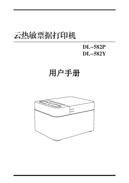
DL-582P/DL-582Y是一款云热敏票据打印机。
具有高打印质量,高速度,高稳定性等特点,可广泛应用于餐饮外卖行业,商超零售行业,票据订单业务,电商等需要接单,打单的场合。
1)噪音小,打印快,接单稳定2)方便快捷更换卷纸3)使用简便,自动接单4)用户系统自定义设置,展现店铺视觉宣传打印机电源适配器使用说明书卷纸图1-3-1开机键(长按)菜单下移键网络指示灯状态指示灯电源线连接口网线连接口(无效接口)流量卡卡槽(无效接口)工厂配置连接口图1-4-1“设置菜单”键(短按)“WiFi设置”菜单快捷键(长按)菜单确定键图1-5-1140.884.5112.6开盖手指着力处连接端向下热敏面向外1.打印机填装打印纸时,卷纸方向应按照下图所示进行填放。
2.将卷纸的外圈纸撕开,并将连接端向下,热敏面朝外,如图示:图3-1-1图3-1-23.将卷纸拉出一段贴靠在出纸口正中,并按纸仓盖中间区域关闭纸仓盖,如图示:图3-1-34.撕掉多余纸张,如图示:图3-1-43.3 指示灯的说明初始安装打印机或打印机存在任何问题是可以执行自检程序“关于本机”,确认如下状态:1)确认已正确连接电源,正确放置打印纸;2)确认打印机处于关机状态,且顶盖已合盖到位;3)长按左键开机,开机后,按右键进入设置菜单,然后进入“关于本机”。
8K93维修手册调试说明

创维集团有限公司研究院警告本手册仅供有经验的维修人员使用,不适用于一般消费者,手册中没有对非技术人员企图维修本产品而存在的潜在危害提出警告或提醒。
电器产品应由有经验的专业技术人员进行维护和修理,任何其它人企图对本手册涉及的产品进行维护和修理将有可能受到严重伤害甚至有生命危险。
1 产品综述1.1 机芯概述8K93机芯是是我们公司与台湾MTK公司合作开发的主要面向大尺寸的高端LCD 3D电视,采用MT5326ACDJ芯片,内置双核的ARM Cortex-A9 900MHz CPU,芯片集成度高,采用单芯片,功能强大,操作系统采用最新的Android 4.0,支持3D ME/MC,支持DTMB,支持HDMI1.4a,USB2.0,支持语音输入功能,内置WIFI。
8K93机芯具有电路设计简洁,功能强大,性能优良和通用性强,工艺设计和成本设计较合理等优点,是目前公司面向高端的智能云电视。
1.2 主要功能1、Android 4.0操作系统。
2、丰富的接收功能。
3、应用商城,在线酷影,搜索、壁纸、任务管理,设置,网址导航,云平台,云健康,健康运动,媒体播放,酷开商场,我的酷开等功能。
4、三屏互动功能。
5、健康屏变功能。
6、屏稳功能。
7、矩阵背光功能。
8、语音博士功能。
9、第三代六基色彩色图像处理技术。
10、3D ME/MC处理技术(功能可选)。
12、内置WIFI功能(功能可选)。
13、数字一体机(功能可选)。
1.3 主要技术规格1、一路模拟电视,一路DTMB输入,两路视频输入,一路分量输入,一路电脑输入,三路HDMI输入,四路USB输入,两路模拟音频输入,一路SD卡输入,一路CA卡DTV输入。
2、支持*.mpg,*.rm,*.rmvb,*mp4,*.VOB,*.DAT,*.AVI,*.VID等格式的影片文件;支持*.mp3,*.wma 等格式歌曲;支持JPEG/PNG/BMP/JIF等格式图片;3、分量/HDMI 支持480I,480P,576I,576P,720P50,720P60,1080I50,1080I60,1080P50,1080P60全高清格式4、支持两路serial flash,支持一路NAND flash.5、支持HDMI 1.4a 3D DTV输入格式,支持MPEG Decoder(MVC)3D DTV输入格式,支持Reald 3D,Sensio 3D,Frame sequential 3D,Line_interlerleave 3D。
得力 得力DL-888D(NEW)标签打印机用户手册 说明书
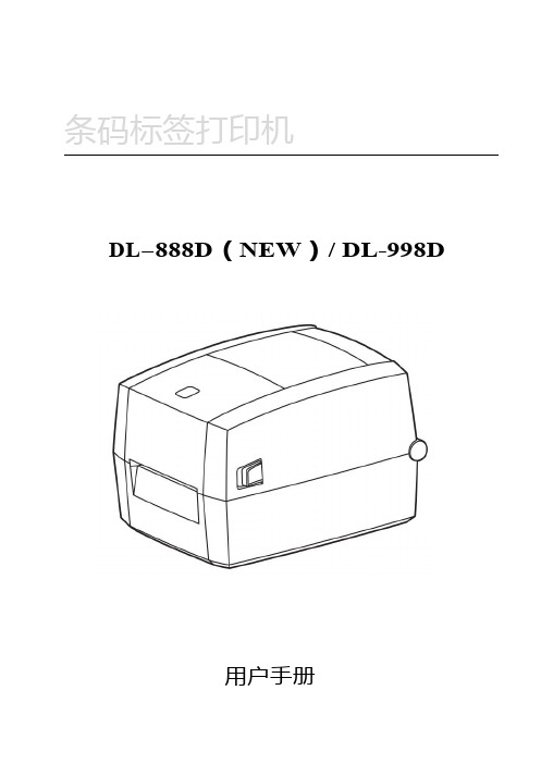
条码标签打印机DL-888D(NEW)/DL-998D用户手册目录手册信息 (1)安全须知 (2)第1章产品简介 (6)1.1开箱清单 (6)1.2外观及组件 (7)1.3产品尺寸 (8)第2章产品规格 (9)第3章安装和使用 (11)3.1安装介质 (11)3.2电源连接 (14)3.3接口连接 (15)3.4标签侦测 (16)3.5操作界面说明 (17)3.6基本功能使用 (19)3.6.1打开/关闭电源 (19)3.6.2打印测试 (19)3.6.3标签学习 (20)3.6.4首张回退 (20)第4章接口 (21)第5章清洁打印机 (22)5.1清洁打印头 (22)5.2清洁传感器、胶辊和纸张路径 (23)手册信息本用户手册包含产品使用、安装等基本信息。
以下手册对各种技术问题和领域有更为详细的介绍。
版本:1.01安全须知在操作使用打印机之前,请仔细阅读下面的注意事项,以免发生人身伤害或设备损坏。
1.安全警告标志——警告:必须遵守,以免伤害人体,损坏设备。
——注意:给出了打印机操作的重要信息及提示。
2.安全注意事项警告:违反以下事项可能会导致严重的伤亡事故。
1)不要同时将几个插头插入一个多孔电源插座中。
•这会导致过热和火灾。
•如果插头潮湿或者肮脏,请在使用前烘干或者擦拭干净。
•如果插头与电源插座不配套,请不要插上电源。
•只能使用标准化的多孔电源插座。
2)您只能使用本包装中供应的适配器。
•使用其它适配器十分危险。
3)不要通过拉扯连接线的方式拔插头。
•这可能损坏连接线,造成火灾或者打印机故障。
4)不要在手潮湿的时候,插或者拔电源插头。
•这可能导致触电。
5)不要用力弯曲连接线,或者将其置于重物之下。
•连接线损坏后,可能造成火灾。
注意:违反以下事项可能造成轻伤或损坏设备。
1)如果发现打印机不明原因地冒烟、发出气味或者噪音,请拔下插头,再采取急救措施。
•关闭打印机,拔下设备的插头。
•在烟消失后,电话联系经销商进行维修。
DLJ-88(12M)型控制板说明书

5
西安迪利捷机电科技发展有限公司
控制板说明书-88
由 UP1 和 UP2 输入的中频电压信号,经 U4B 转换成方波信号, 输入到 U11 的 12P。由 U11 的 64P、67P 输出的逆变触发信号,经 U7 隔离放大后,驱动逆变触发 C MOS 晶体管 Q5、Q6 、Q16、Q17。 U4A 和 U4D 构成逆变压控时钟,输入到 U5 的 83P;同时又由 U9 进 行频压转换后用于驱动频率表。FHZ 微调电位器用于整定外接频率表 的读数。
1
西安迪利捷机电科技发展有限公司
公司简介
控制板说明书-88
西安迪利捷机电科技发展有限公司(西安迪利捷科技 \DeLiJayst),是以研发、设计、制造及销售感应加热设备及控制线路 为主的企业。公司人员配备合理,其中工程技术人员占公司人数的 40%以上,具有自主研发电子、自控、机械等多方面的能力。在不断 吸收国內外先进科技技术的同时,长期与西安电炉研究所、交通大学、 西安石油大学、浙江大学等多家科研单位合作,已成功开发出用于淬 火、透热、熔炼、钎焊、烧结等多领域的高、中、低频成套先进设备, 特别是近两年来开发出的大功率Insulated Gate Bipolar Transistor电 源,填补了国内大功率超音频感应加热用电源的空白;为了适应行业 发展需要,公司技术人员经过多年的不懈努力,相继开发出DLJ-3; DLJ-6;DLJ-7;DLJ-88;DLJ-24;DLJ-G3 用于高、中、低频感应 加热设备的控制主板,其市场占有率达到感应加热控制板行业的 60% 以上。在开发新产品的同时我公司时刻遵循“依靠科技进步 诚信务实 发展”的原则,依靠强大的技术力量,为客户提供高品质、高性能的 产品,公司产品以其可靠的质量与良好的售后服务在广大客户中赢得 较高的赞誉。
- 1、下载文档前请自行甄别文档内容的完整性,平台不提供额外的编辑、内容补充、找答案等附加服务。
- 2、"仅部分预览"的文档,不可在线预览部分如存在完整性等问题,可反馈申请退款(可完整预览的文档不适用该条件!)。
- 3、如文档侵犯您的权益,请联系客服反馈,我们会尽快为您处理(人工客服工作时间:9:00-18:30)。
如果是个别部位不充气、 则从后向前依次检查气阀绕组 是否开路或短路。主控制板上接口电路 ULN2004 及锁存器 CD4094 有无损坏,可用替换法检修。
八、热疗器工作异常:
1、故障原因: 1.1、热疗器电源变压器损坏。 1.2、热疗器电源控制板故障。 1.3、热疗器内部故障。 2、检修流程:
检修开始 打开位于按摩椅前部的电源盒上盖,测量热疗器的工作变压器是否 有 16V×12 交流电压输出 ?
总电源开关及保险管是否良好? 否 更换电源开关或保险管。 是
主变压器次级 110V 电压是否正常? 否 更换变压器。 是
电源板输出 DC5V、DC12V、VEE-24V AC4V 是否正常? 否 检修二次变压器及电源板。 是
主板上 DC12V(继电器线圈电源脚) DC5V(18F452 11 脚 32 脚)是否正常?否 检查电源板到转插板再到主板的线路有无开路或虚焊。
检查电动推杆到主板部分的限位,检测线是否开路?C119、C120、C121、C122 及 R121、R122、R123、R124 有无漏
电或开路?
否
是 更换损坏的阻容元件,并把各插件插接牢固。
更换单片机 PIC18F452。
修复。检修结束。
五、机械手不能上下行走:
1、故障原因:
1.1、行走电机损坏,移相电容损坏。
一、特别提示:
本维修手册只针对于有一定电器维修技能的专业的人员。 因维修过程中要去掉按摩椅的绝缘防护。还要进行带电检测。 所以在此提醒非专业检修人员请勿擅自拆修,以免引起触电 伤害!
二、按摩椅电气结构框图
电源输入
变 电压源器输
电源板
主板
信
驱
号
动
控
部
制
分
转插板
热疗器
各部执行单元
Mp3 音乐播放板
手控板
1、通电后灯不闪动一下且 U 盘灯(如果有)也不亮。
2、检修流程:
检修开始
开机状态检测气泵电源输出插座有无交流 110V?
(转插板上)
有 气泵损坏。
无
查主板 Q103(BTA12)是否损坏?及对应的光耦 U111(M0C3063)1 脚是否为 1.2V? 有 BTA12 损坏或后线线路有开路故障。
无 查 R129 390Ω电阻。单片机 18F452 损坏。
机的直流电流是否为 45Ω左右? 否 电机损坏,更换电机。
是
检测转插板上揉捏、拍打插头处有无 DC60V-110V 电压? 是 查转插板到揉捏、拍打电机间的连线。
否
测量主板上光耦 U112(拍打控制)3 脚电压是否在 6.6V-9.5V 之间?U113 3 脚电压是否 7.7V-11V 之间变化?
是 对应的运算放大器 LM324 损坏或 MOS 三极管 IRF840 损坏。
是 检查转插板到电动推杆间的线路。
主板上 CON104 插座上是否有 DC110V 输出? 是 主驱动板到转插板有开路故障。
否
主板控制部分锁存器 74Hc573 5、6、7、8 脚电压是否随按键操作在 0V-5V 间跳变?
否
是 对应的光耦 U115(小腿升降)、U116(靠背升降)
及 ULN2004 各换向继电器有损坏,更换。
否
单片机 34 拍打、35 揉捏是否有 2V 电压输出? 是 控制输出锁存器 74HC573 或对应的 P521 光耦损坏。
否
单片机 18F452 损坏,更换。
七、充气按摩功能异常:
1、故障原因:
1.1、气泵损坏或无工作电压。
1.2、如果是个别部位不充气,则对应的气阀损坏或气管折住。
1.3、信号控制板上。
1.2 主板→转插板→行走电机间线路有开路。
1.3、主板故障。
2、检修流程:
检修开始→在背部定位状态,按上行或下行电机上是否有交流 110V 电压?
是 行走电机损坏或移相电容无容量。用万用表测电机电阻
否
应为 2×25Ω电容容量为 14UF。
测量主板上光耦 V109、V110 的 1 脚,电压是否在 5V-1V 间变化?
有
无 供电变压器损坏更换。
热疗器供电板上是否有 DC5V 电压输出? 无 源板上 47Ω水泥电阻或 7805 损坏。
有
检测电源板上开关三极管 TIP147,控制管 TIP122 是否损坏?
否
是 更 换。
热疗器内温度控制电路损坏。更换热疗器。
九、音乐播放功能异常及排除
故障现象
检修及排除方法
通电后观察 MP3 板上的红、绿指示灯。
三、整机不工作:
1、故障原因:
1.1、电源插座无电或插接不良。 1.2、总开关未开,保险管开路。 1.3、220V/110V 主变压器损坏。 1.4、电源电路故障。 1.5、单片机 pic18F452 未工作或损坏,手控板故障。
2、故障检修流程图
检修开始→电源插座是否有电?插接是否良好? 否 检修电源插座。 是
是 可控硅 BTA12 损坏,或 110V 电源没有送到 BTA12 上端。
否
单片机 18F452 损坏,更换修复。
பைடு நூலகம்
六、揉捏或拍打功能工作异常:
1、故障原因:
1.1、揉捏或拍打电机损坏。 1.2、线路或插接件松脱。 1.3、信号控制板及驱动板故障。
2、检修流程:
检修开始
打开按摩椅后背盖,在行走架处拔下两只电机的插件,用万用表测两电
是 手控板内的 DC5V 电压是否正常? 否 检查转插板到手控板上的线路有无虚焊开路处。
是 更换 18F452 13、14 脚间的 4MHZ 晶振。或手控板内的 4MHZ 晶振,能否开机?
否 更换主芯片 PIC 18F452 修复。 是 晶振不良、损坏。更换修复。
四、电动推杆不工作:
1、故障原因:
D L K 得力康电子有限公司
维修手册 (本手册适用于 H008、H008A、H009、H009A、H010 按摩椅)
目录
一、特别提示 二、整机框图 三、通电后整机不工作 四、电动推杆不工作 五、机械手不能上下行走 六、揉捏或捶打功能工作异常 七、充气按摩功能异常 八、热疗器工作异常 九、音乐功能异常 十、手控板故障 十一、常见故障的快速排除
1.1、电动推杆损坏。
1.2、电源输出插件或限位检测插件松脱。
1.3、驱动板上元件故障。
2、检修流程:
检修开始→拔下靠背小腿的两只电动推杆的插件,
把不工作那只的电源线插到另一只上看是否有工作? 是 电动推杆损坏,更换电动推杆。
否
说明没有驱动电源输出。检测转插板上有无对应的电压输出(DC110V)?
否