基于linux的实时图像采集系统设计与实现
在Linux平台上基于QT的动态图像采集系统的设计

本 程 序 共 由 Q plao 、 Wi e、 B So AC D摄像头将模拟图像送人图像采 C 集卡转换成数字图像信息 , 再送入图像采集终端 , 图 像采集终端获得 图像数据后进行处理并显示 图像。 本系统可应用 于远程检测和远程监控等多个领域。 系统 总体 方案如图 1 所示 。
发者建立艺术级的图形用户界面所需 的所用功能。
圈 1 系统总体方案
石油工业计算机 应 用 20 年第1卷第3 08 6 期
12 图像 采集卡 .
2 9
过程 。其程序流程如图 4所示。采集终端给串口发 送命令后 ,T9 25 开始初始化过程, A 8 C0 1 然后, 初始化 图像采集卡模块, 设定图像采集模式 , 启动采集过程。
0引 言
随着 信息 技术的飞速 发展 , 信息 采集不 再停 留在
在计算机控制领域 , 经常需要实现计算机之间或 计算机与其他设备之间的通信, 串口通信作为一种灵 活、 、 方便 可靠的通信方式被广泛采用 , L u 下的串 在 ix n
行通信编程主要是依靠内核提供的 t n s e i 结构对串 no 口进行 参数设置 , 并对串 口对应的设备文件进 行读写 。
图像采集卡完成模拟图像信号的采集输入, 并将 模拟图像信号转换为数字图像信号 , 并传输给图像采 集终端接口。其内部逻辑框图如图 2 所示。
接下来 , 系统将连续查询图像采集控制寄存器的值 ,
查询是否完成一幅图像的采集 , 如果没有完成 , 继续 查询图像采集控制寄存器 , 直到查询到采集完成一幅 图像, 启动图像读取子程序 , 把图像数据从 F O中读 I F
于Q T的动态 图像
系 统 的 设 计
基于Linux的图像采集及通信系统
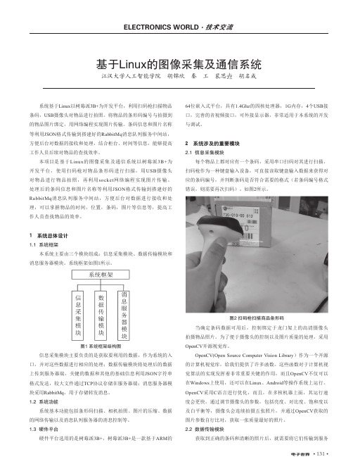
• 131•系统基于Linux 以树莓派3B+为开发平台,利用扫码枪扫描物品条码,USB 摄像头对物品进行拍照。
将物品的条形码编号与拍摄到的物品图片绑定,用网络编程实现图片传输。
条码信息和图片名称等利用JSON 格式传输到搭建好的RabbitMq 消息队列服务中间站,方便后台对数据的接收和处理,结合柜台、时间等信息,能够提高工作人员后续对物品的查找效率。
本项目是基于Linux 的图像采集及通信系统以树莓派3B+为开发平台,使用扫码枪对物品条形码进行扫描,用USB 摄像头对物品进行物品拍照,再利用socket 网络编程实现图片传输。
处理后的条码信息和图片名称等利用JSON 格式传输到搭建好的RabbitMq 消息队列服务中间站,方便后台对数据进行接收和处理,可以掌握物品的时间,位置,条码,图片等信息等,提高工作人员查找物品的效率。
1 系统总体设计1.1 系统框架本系统主要由三个模块组成:信息采集模块、数据传输模块和消息服务器模块。
系统框架如图1所示。
图1 系统框架结构图信息采集模块主要负责的是获取要利用的数据,作为系统的入口,并对这些数据进行相应的处理;数据传输模块将处理后的数据上传到服务器端,关键的数据和其他的基础信息利用JSON 字符串格式发送,较大文件通过TCP 协议存储在服务器端;消息服务器模块采用RabbitMq ,用于存储转发消息。
1.2 系统功能系统基本功能包括条形码扫描、相机拍照、图片的压缩、数据的网络传输以及消息队列服务器的消息控制等。
1.3 硬件平台硬件平台选用的是树莓派3B+,树莓派3B+是一款基于ARM 的64位嵌入式平台,具有1.4Ghz 的四核处理器,1G 内存,4个USB 接口,完善的音视频接口,可外接显示器,非常适用于本系统的开发与调试。
2 系统涉及的重要模块2.1 信息采集模块每个物品上都对应有一个条码,采用串口扫码对其进行扫描,扫码枪作为一种键盘输入设备,可直接读取键盘输入数据来获得对应的条码编号,并判断条码是否符合需要的格式(若条码编号格式错误,则需要再次扫码)。
基于Linux平台的图像采集系统的设计与实现

系统 ,而 Ln x系统作为一个开放 的操作 系统具有 独立性 、 iu
创新性 、可扩展性 等优点 ,适合 开发 独立 的具有创 新性 的
图像采集系统_ ,但 由于 Ln x系统是源码开放 ,没有 一 7 。 iu
-
7作模 型并且设计 实现 了系统 的硬件平 台和软件平 台,实验 结果表 明,该 系统可 以安全 可靠的控制全 方位 转动的摄像机 对 - -
环境信 息进行 高清晰 图像采集 ,有效的提 高了图像采集速 度和准确 性。
关 键 词 :Ln x 台 ; 图像 采 集 ;视 频 处 理 ;模 块 化 ;可扩 展 性 iu 平 中 图法 分 类 号 : 3 2 1 TP 0 . 文献 标 识 号 :A 文章 编 号 :10 —0 4 (0 2 62 3 —4 0 07 2 2 1 )0 —3 40
后来 随着计算机 技术 的发展 ,采 集卡作 为 图像 采集 系统不 可缺少 的硬件逐 渐被应 用在 图像采集 系统 中 ,利用 图像采 集 卡可以轻松 的将模 拟摄像 机 的图像信 号采集 进来 进行处
理 ,采集卡 的软件界 面也很轻松 的应用 在图像采集 系统 中, 所以利用采 集卡 和模 拟摄像 机可 轻松 的完成 图像采 集 系统 的设计 ,模 拟摄 像机 的 图像 采集技 术成熟 易实 现 ,但 图像 采集的速度慢 、抗干扰 能力 差 ,由于 噪声多 造成采 集 的图 像不清晰 ,操作 不方便 ,由于这 些缺 点这种技 术 已渐渐 的
在早期的 图像采集 系统 的研究 中,由于 硬件大 多采 用 的是装有 C MOS芯片的摄像机 ,由于 C S芯 片只能采集 MO 模拟信号 ,所 以要使 用模Байду номын сангаас摄 像机 进行 图像采 集系统 的研 究 ,还需要额 外 的对模 拟 信号 进行 处 理 以得 到 数 字信 号 。
基于嵌入式Linux的图像采集系统研究的开题报告
基于嵌入式Linux的图像采集系统研究的开题报告一、研究背景图像采集系统广泛应用于工业自动化、视频监控、医疗影像等领域。
在图像处理的应用中,硬件平台的选择往往对系统的性能和成本产生巨大影响。
嵌入式Linux系统因其开源性、灵活性以及定制性等特点而被广泛应用于嵌入式系统和实时应用中。
目前,越来越多的嵌入式图像采集系统采用基于Linux的操作系统并集成开源的图像处理库,以提高系统的适应性和可升级性。
二、研究目的和意义本研究旨在探究基于嵌入式Linux的图像采集系统的设计与实现,突破传统基于固定硬件平台的图像处理系统,开发出更灵活、更优化的图像采集系统实现嵌入式图像处理方案。
探索基于Linux系统的图像采集系统设计方法和实现方案,具有以下意义:1. 提高图像采集系统的性能和稳定性;2. 加深对嵌入式Linux系统的理解和应用;3. 推动嵌入式设备在图像处理领域的应用和发展;4. 探索嵌入式系统和实时应用的领域研究。
三、研究内容及技术路线1.研究内容(1)嵌入式Linux系统架构及应用设计原理分析;(2)图像采集系统基础架构设计,包括硬件平台、软件系统等;(3)图像采集模块的设计与实现,采用优化算法对采集到的图像数据进行预处理和滤波,提高图像质量;(4)利用开源的图像处理库,对采集到的图像数据进行后期处理,包括去噪、对比度、亮度等;(5)生成完整的硬件和软件开发文档,方便系统维护和升级。
2.技术路线(1)嵌入式Linux系统的配置和移植;(2)基于ARM Cortex-A 核心的嵌入式图像采集系统硬件设计;(3)采用C/C++语言开发图像采集系统应用程序;(4)应用开源的图像处理库进行图像处理;(5)结合Qt图形界面库开发人机交互界面。
四、预期成果和研究计划1.预期成果(1)实现基于嵌入式Linux的图像采集系统,内部集成优化算法和图像处理库,完成对采集到的图像数据的处理和优化;(2)研究出图像采集系统的整体设计、开发指南,包括硬件和软件方面的开发文档;(3)系统性能测试和性能分析,评估系统优化和改进效果。
基于ARM-Linux的图像采集和无线传输系统设计

X cl P A 7 理 器 连 接 了一 个 6 Mbt N N l载 程序 和 内核 映像 , 并作 为根 文件 系统 ,4 y 6 Mbt e S R M 作 为 内存 , S I 接 无 线 网卡 , S 2连 接 摄 像 头 。 系 D A UB 连 UB
d i1 . 9 9 j i n 1 7 — 4 . 0 0 0 . 1 o :0 3 6 / . s . 6 11 1 2 1 . 5 0 2 s 0
基 于 A M- iu R Ln x的 图像 采 集 和 无 线 传 输 系统 设 计
田泽 康 , 德 华 李
( 中科技 大学 图像 识别 与人 工智 能研 究所 , 汉 4 0 7 ) 华 武 3 0 4
图像采集和传输系统 的硬件系统 由开发板 、 by 30 WeeeV 0 0 U B摄像头 、 S 中兴 MF7 U无线网卡等构成 , 图 2所示 。 63 如
De i n o sg fARM - n x-a e m a e a q iii n - u - s d i g c u sto Li b a d r ls r n m iso s se n wiee s ta s s in y t m
摘 要 : 绍 了一 种 基 于 嵌 入 式 l u 介 i x的 实 时 图 像 监 控 系统 的 设 计 和 实 n 现方 法 。 系统 以 X c l P 2 0处 理 器为 核 心 , 载 US sae XA 7 搭 B摄 像 头 和 无 线 网卡 构 成 硬 件 平 台 。 Ar Liu 以 m- n x为 软 件 平 台 。 该 平 台 上 实 现 了 在 实 时 图像 的 采 集 , E 4压 缩 和 3 无 线 传 输 。M P MP G- G EG- 法 的 采 4算 用减 小 了网 络 的 压 力 。 节 约 了成 本 。 随 着 3 网 络 的 不 断 发 展 , 系 又 G 本 统将在 3 G时代有着广阔的应用前景。 关键 词 :图 像 采 集 ; 入 式 系 统 ; C 嵌 W DMA;A m- iu r Ln x 中 图分 类 号 :T 2 P7 文 献 标 志 码 :A
基于嵌入式linux的视频图像采集
计算机教学
基于嵌入式 li 林 智
(闽江学院计算机科学系 )
本文主要介绍在 linux操作系统 、ARM XSBase270平台上 ,利用 linux内核中已经植入 video4 linux函数库的数据结构和 AP I函数 , 通过 OV511摄像头实现视频采集的方案 ,本方案采用 Q t Designer为开发环境 ,以效率较高的 mmap (内存映射 )方式截取视频 ;可保存单 张的图片 ,也可保存为视频 。
四 、视频采集的实现 1. 视频采集时一些参数的初始化 定义的函数原型为 v4 l_grab_ init ( v4 l_device 3 vd, int w idth, int height) 参数 vd为自定义的数据结构 struct _v4 l_device,设置宽 、高 、帧使用情况的 属性等 。该函数的重点代码如下 : vd - > mmap. width = width; vd - > mmap. height = height; vd - > mmap. format = vd - > p icture. palette; vd - > frame = 0; vd - > framestat[ 0 ] = 0; vd - > framestat[ 1 ] = 0; vd - > frame为当前帧 , framestat[ ]标记该帧是否已被使用 。 0 表示未 被使用 2. 获取支持的帧数和基地址 v4 l_get_mbuf ( v4 l_device 3 vd ) v4 l_mmap ( v4 l_device 3 vd) 首先 ,使用 V ID IOCGMBUF命令将摄像头的帧缓存的大小映射到 vd >mbuf. size,正使用的帧 (0或 1)映射到 vd - > mbuf. frames中 ,执行完该命 令后 ,就可以用 mmap函数将缓存映射到内存中了 。 if ( ioctl( vd - > fd, V ID IOCGMBUF, & ( vd - >mbuf) ) < 0) { perror( " v4 l_get_mbuf: V ID IOCGMBUF" ) ; return - 1; } 其次 ,要将 mbuf获取的数据通过 mmap 函数映射到 vd - > map 中 ,这 样才能对获取到的数据进行操作 。在 mmap函数里 PROT_READ 表示可读 取该内存页 , PROT_WR ITE 则是可写入 , MAP_SHARED 则是让这块 map2 p ing的区域和其它进程共享 。第一个参数为 0 是启始位置 , vd - > mbuf. size则是长度 ( length) 。 vd - > fd则是设备的文件描述符 ,最后一个参数是 offset。 if ( ( vd - >map = ( unsigned char3 ) mmap ( 0, vd - >mbuf. size, PROT_READ | PROT_WR ITE,MAP_SHARED , vd - > fd, 0) ) < 0) 3. 视频帧的截取 v4 l_grab_start( v4 l_device 3 vd, int frame)是真正将影像放到 mmap 里 的函数 。参数 vd为自定义的数据结构 struct _v4 l_device, frame值为 0或 1, 意为第 0帧或第 1帧数据 ,成功返回 0,失败则为 1;实现代码如下 : vd - > mmap. frame = frame; if ( ioctl( vd - > fd, V ID IOCMCAPTURE, & ( vd - > mmap ) ) < 0) { perror( " v4 l_grab_start: V ID IOCMCAPTURE" ) ; return - 1;
基于嵌入式Linux平台的图像采集与传输设计
基于嵌入式Linux平台的图像采集与传输设计随着技术的迅猛进展和在信息行业中的广泛应用,视频采集与传输系统作为远程、可视电话会议和工业自动控制领域的一项核心技术,近年来已经得到了飞快的进展。
本文在基于嵌入式Linux系统平台上,采纳摄像头捕获视频信号,利用V4L内核应用编程接口函数,实现了视频延续帧图像的采集,并保存成文件的形式利用无线传输方式传输给接收端。
这里着重研究视频采集发送端的实现。
1 系统组成1.1 统的硬件构成本系统包括发送端和接收端2部分,两部分均采纳Samsung公司生产的处理器做硬件开发平台。
S3C2410在片上集成了丰盛的组件:分开的16 KB命令Cache和16 KB数据Cache、用于虚拟存储器管理的MMU、支持STN和TFT的控制器、NAND Flash启动装载器、具有片选规律和SDRAM 控制器的系统管理器、3通道UART、4通道DMA、4通道定时器、I/O 口、RTC、8通道10位和接口、I2C接口、I2S总线接口、USB主设备、USB从设备、SD卡和MMC卡接口、2通道的SPI以及PLL时钟发生器,还采纳了AMBA(advanced micrcocontroller bus architecture)新型总线结构。
应用S3C2410处理器平台搭建的发送端硬件结构1所示:包括S3C2410处理器、RS232接口、JTAG接口、RJ-45接口、SDRMA、Flash、电源、通过USB口衔接的视频采集模块和通过USB接口衔接的视频放射模块。
RS232串口用于人机交互及低速数据的收发,应用电平转换芯片MAX-323举行串口电平和TTL/电平的转换。
JTAG接口用于下载Bootloader。
RJ-45接口用于和以太网衔接,下载操作系统Linux内核、根文件系统和应用软件。
SDRMA用于系统的数据存储器、Flash用于系统的程序存储器。
应用S3C2410处理器平台搭建的接收端硬件2所示:与发送终端相比,多了SD卡和LCD。
基于嵌入式Linux的图像采集系统的开题报告
基于嵌入式Linux的图像采集系统的开题报告一、选题背景和意义随着数字技术的发展,数字图像的采集及处理技术越来越受到人们的关注,应用于许多领域,如医疗、安防、航空航天、交通等。
随着市场需求的增加,图像采集设备也不断地提高其需求,需要更高的分辨率、更高速的传输等优化,同时也对设备体积、功耗等有较高的要求,因此,采用嵌入式Linux作为系统核心开发图像采集系统可以成为很好的解决方案。
二、研究目标本文的目标在于,基于嵌入式Linux平台,设计一种简单、可靠、易扩展和高性能的图像采集系统,实现以下功能:1.支持多种图像传感器,如CCD、CMOS等;2.支持多种图像采集接口,如USB、SDIO、CSI等;3.支持远程图像采集和网络传输功能;4.支持图像处理和算法实现;5.支持图像存储和传输。
三、研究内容和方法1.嵌入式Linux系统的构建通过嵌入式Linux进行图像采集系统的开发,需要首先确定主板选型,并根据主板接口及资源情况进行嵌入式Linux系统的构建。
2.图像采集模块的实现根据需求确定采集模块的类型以及接口方式,对采集模块进行硬件接口设计、驱动开发等,以保证采集模块能够正常工作。
3.图像处理和算法实现采用C/C++和OpenCV等工具对图像进行处理和算法实现,如图像增强、边缘检测、图像分割等,并进行测试和优化。
4.图像存储和传输设计图像存储和传输模块,支持本地存储和远程传输功能,并进行测试和优化。
四、预期目标本研究计划达到以下预期目标:1.成功实现基于嵌入式Linux的图像采集系统,具有多种采集接口和多种图像传感器的兼容性;2.成功实现图像处理和算法实现,具有一定的图像分析能力;3.成功实现图像存储和传输,具有一定的远程图像采集和传输能力;4.完成系统的测试、验证和优化,使系统具有稳定性、可靠性和高性能等特点。
五、进度计划1-2月:文献研究和系统设计3-4月:嵌入式Linux系统构建和驱动开发5-6月:图像采集模块的实现和调试7-8月:图像处理和算法实现,系统整合和测试9-10月:图像存储和传输模块的实现和调试11-12月:系统的测试、验证和优化六、预计研究结果本文将构建一种简单、可靠、易扩展和高性能的图像采集系统,并实现多种采集接口和多种图像传感器的兼容性,具有一定的图像分析能力和远程图像采集和传输能力,同时达到了稳定性、可靠性和高性能等特点。
实时图像获取与显示系统基于嵌入式Linux设计说明书
International Conference on Information Sciences, Machinery, Materials and Energy (ICISMME 2015)Design of Real-time Image Acquisition and Display System Based onEmbedded LinuxXiaohan Guan, Wangyi ShiCollege of Electronic Information Engineering, North China University of Technology, Beijing,100041, ChinaKeywords: embedded system, linux, image acquisition, video4linux2, framebuffer, usb camera. Abstract. For the need of real-time fast image processing problems in the field of pattern recognition, this paper proposes an image acquisition and display method based on embedded technology. In order to solve the problem efficiently, we present a programming technology of Video4Linux2 (V4L2), and the technology of V4L2 video capture application program interface is used to write the image acquisition program, as a result, the image acquisition of USB camera based on Ipassion IP2977 DSP control chip is realized. In addition, the Libjpeg library is used to unzip the images collected, the real-time image is displayed by framebuffer. Because the system uses new video programming interface and standard library functions of Linux, the modular structure to realize the required function has the very strong practical significance to the subsequent image application development based on Linux kernel.1.IntroductionTraditional visual image system is based on the camera, image acquisition card and PC as a whole, this vision system can not meet the demand of real-time image processing in embedded environment. At present, the market has the general image system taking DSP as the data processing unit, but the cost is higher. With the development of domestic and international vision system, the visual image system based on embedded Linux is increasingly popular. Compared with the traditional system the embedded system not only has the advantages of small size, low cost, high stability, real time and so on, but also has practical value, so it has been widely used in intelligent transportation, computer vision, communication and other fields[1]. In terms of hardware, the USB interface camera which has high sampling rate, good versatility is favored in the embedded image acquisition applications. In terms of software, the embedded Linux is widely used in middle and low level embedded devices because of open source code, rich resources, powerful kernel function, stable performance. This paper uses the arm9-based S3C2440 processor hardware platform to achieve a better acquisition and display of digital image data in the Linux operating system.2.Structure of the hardware and operating systemThe system hardware structure is as shown in Fig.1, the core of hardware platform adopts embedded microprocessor S3C2440, outside is connected with a USB camera and LCD display device. S3C2440, the Samsung Corp production of low power consumption and high degree of integration is a 16/32 bit RISC embedded microprocessor. USB Host controller is directly connected with a video camera to get the image acquisition data which ultimately will be displayed on the LCD. In the S3C2440 and Linux operating system, the method of collecting and decoding a video image is different from traditional DSP system. In the past such as image compression, image synthesis operations involve a lot of calculation, so can only be handled by DSP, now since the ARM series processor has high performance to calculate and process, the coding and decoding of video image can be realized much better[2]. At the same time, ARM has a strong control function, the embedded Linux operating system also can be easily transplanted to ARM, so the embedded system that is composed of ARM and Linux has a great advantage.Fig.1: Structural diagram of the system hardware3.Image acquisition based on the v4l2V4L2 is Video For Linux Two, which provides a set of APIs for imaging equipment in the Linux kernel, it can realize image acquisition, AM / FM radio, image CODEC and channel switching function with the appropriate video acquisition device and the corresponding driver. At present, V4L2 is mainly applied to the video streaming system and embedded image system, which is widely used in teleconferencing, video telephone and video monitoring system.The application of image acquisition of USB camera under the framework of V4L2 is mainly divided into two steps that include the successful driver of USB camera and image collection.3.1Driver of USB cameraThe key to drive USB camera which is based on IP2977 chip is to ensure the successful loading of USB bus driver, V4L2 standard and IP2977 chip driver in the kernel[3]. Therefore, it is necessary to reconfigure and compile the kernel. Specific operation method is: run command “cp config_ok ./.config、make menuconfig” one after the other in the Linux-3.4.2 source file directory, enter the configuration options of system kernel, and then separately add the USB bus driver, V4L2 standard and the IP2972 driver.i) The addition of USB bus driverAfter running the command “make menuconfig”, select the following in the system configuration to support the USB bus driver.Device Drivers --->[*] USB support --->{*} Support for Host-side USB[*] USB device filesystem (DEPRECATED)[*] USB device class-devices (DEPRECATED)<*> OHCI HCD support<*> USB Mass Storage support[*] HID Devices --->{*} Generic HID support[*] /dev/hidraw raw HID device supportSCSI device support ---><*> SCSI device support[*] legacy /proc/scsi/ support<*> SCSI disk support<*> SCSI tape supportii) The addition of V4L2 and IP2977 device driverLoading the driver of IP2977 control chip has two ways which are static loading and dynamic loading[4].Static loading refers the drivers are compiled into the kernel directly, which can be called directly after the boot without requiring any loading or unloading command. Dynamic loading refers to the use of Linux module features, through the command “insmod or modprobe” to mount the .ko kernel object file and load the module after the boot, and through the command “rmmod” to unload the module when not needed. As the module itself has not been compiled into the kernel, once the module is loaded by the kernel, it is used flexibly the same as the kernel of other parts, but the shortage is that each call is required for loading and unloading module through the command, the operation is trouble.In view of hardware resources are adequate, for the convenience of using, this chip driver is loaded by static way, which is the IP2977 chip camera driver is compiled into the kernel, the specific configuration options are as follows:-> Device Drivers<*> Multimedia support ---><*> Video For Linux[*] Video capture adapters (NEW) --->[*] V4L USB devices (NEW) ---><*> USB Video Class (UVC)After completion of the above addition, exit the kernel configuration, save the configuration menu, successively run the command “make, make uImage” in the terminal, compile the kernel image file uImage, burn the generated uImage to development board, and reboot development board with the new kernel. At this point, you can see the camera driver has been successfully compiled into the kernel from the startup information, the information is as follows:ohci_hcd: USB 1.1 'Open' Host Controller (OHCI) Drivers3c2410-ohci s3c2410-ohci: new USB bus registered, assigned bus number 1usbcore: registered new interface driver uvcvideoUSB Video Class driver (1.1.1)When the USB camera is inserted, the system can correctly identify the USB camera, and the output information in serial port is as follows:usb 1-1: new full-speed USB device number 2 using s3c2410-ohciuvcvideo: Found UVC 1.00 device <unnamed> (1b3b:2977)input: UVC Camera (1b3b:2977) as /devices/platform/s3c2410-ohci/usb1/1-1/1-1:1.0/input/input03.2The specific implementation of image acquisitionAfter development board recognizes camera successfully, images can be captured in the embedded Linux. For the image acquisition, there are two ways that are read()-based direct read mode and mmap()-based memory mapped mode[5]. The read()-based method is to read data from the kernel buffer to the user space memory, while in the method of mmap() process achieves shared memory each other by mapping the same file, which is that the image data buffer of camera and the image data area accessed by users share a memory region, thereby bypassing the kernel buffer district. The file is mapped into the user process address space, files can be accessed by the process the same as ordinary memory, without calling the operations of read()and write(). Because the process can directly read and write memory without copying any data, the use of shared memory approach accelerates I/O access, improves efficiency. In view of the above advantages, this paper adopts the way of mmap() to get image. Video capture process based on V4L2 is as shown in Fig.2.Fig.2: the video capture processThe concrete realization process of the image acquisition is as follows[6]:i) Open the camera equipmentAs the system equipment file is required to access the camera device in the Linux, we must create and set up the camera device file, before the file descriptor can be obtained by the following program code.iFd = open(strDevName, O_RDWR);ii) Get the camera equipment informationFirst of all, we can find the header file videodev2.h in the kernel source code, this header file defines all the data structure and function of the application that we will write. Of course, firstly we need to obtain the camera information, understand the camera performance through the v4l2_capability structure in the header file, and read out the unit according to the following program code.struct v4l2_capability tV4l2Cap;iError = ioctl(iFd, VIDIOC_QUERYCAP, &tV4l2Cap);iii) Set the image collection formatAfter modifying the last step camera equipment information obtained, the following function can be called to set the property of camera.iError = ioctl(iFd, VIDIOC_S_FMT, &tV4l2Fmt);In program testing this device cannot be initialized to the RGB format that can be shown directly by LCD, so in the subsequent image processing, converting JPEG format to RGB format is required.iv) Apply for cache spaceCompared with the original V4L application programming interface, the biggest change is that equipment driving cache numbers can be customized in the new interface, so the performance of the program is improved significantly in the practical application. With the following function to apply for a few pieces of cache space at the start of image acquisition, the image data collected will be firstly stored in the cache space which has been applied for.iError = ioctl(iFd, VIDIOC_REQBUFS, &tV4l2ReqBuffs);v) Start the camera equipmentFirst, use the order parameter VIDIOC_QUERYBUF IOCTL in ioctl function to define each cache offset and size, then use mmap () function to map the device cache into user space, and the starting address of application in the memory mapping will be returned. After the memory mapping is completed, it also cannot start the image acquisition, need to put the memory determined into the queue by the command parameter VIDIOC_QBUF in ioctl function, and finally the following function is used to start the camera to capture the image data.iError = ioctl(ptVideoDevice->iFd, VIDIOC_STREAMON, &iType);vi) Close the camera equipmentAfter the acquisition is completed, to turn off the device, recover the system resources is required, so as to avoid memory leaks. The details are as follows:iError = ioctl(ptVideoDevice->iFd, VIDIOC_STREAMOFF, &iType);4. Image decompression based on libjpegBecause the camera data collected based on the IP2977 control chip is JPEG coding format, the data cannot be shown directly in the Framebuffer equipment, extracting the RGB encoding format of the data is needed, before the data can be written to the Framebuffer device to display.Libjpeg is a widely used JPEG compression/decompression library[7], it can read/write the image file in accordance with the standard of JPEG compression, through the Libjpeg library, every time the application can read one or a plurality of scanning lines from the image of JPEG compression, such as color space conversion, down sampling/up sampling, color quantization andFig.3: Process of JPEG decompressionThe image data extracted by libjpeg is stored in the form of a scan line that is a row of pixels in the image. For color images, each component is composed of three bytes, three bytes constitute a pixel on scanning line according to the sequence of R, G, B. For the scanning line the reading is in accordance with the top-down order, that is to say, the scanning line at the top of the image is read into storage space firstly by the function jpeg_read_scanline () ,followed by the second scanning line, and finally the scan line of the bottom edge of the image is read into memory space.5.Image display based on the framebufferFrameBuffer, it serves as the basis for graphical facilities, is the basic function library of other senior graphics or graphical applications. This interface summarizes the display device to a frame buffer. The user can think of it as an image of display memory, but does not need to care about the physical memory location, form feed mechanism and other details, these are accomplished automatically by FrameBuffer device driver[8]. As long as it is mapped into the process address space, you can conduct read/write operation directly, and a write operation can be immediately reflected on the screen.The device file is /dev/fb* for Framebuffer, where the value is 0~31. The /dev/fb0 is often used in Framebufer equipment. Because the embedded system has only a frame buffer device in general, the method of operation is that the Framebuffer equipment is mapped to memory through memory mapping mechanism, which can improve the efficiency. If the function mmap() is called successfully, the memory space mapped can be used to read/write in the program, and all read / write operations will be converted to I/O operation by the operating system kernel, the simple use of the program is as follows:static struct fb_var_screeninfo g_tFBVar;static struct fb_fix_screeninfo g_tFBFix;g_fd = open(FB_DEVICE_NAME, O_RDWR);ret = ioctl(g_fd, FBIOGET_VSCREENINFO, &g_tFBVar);ret = ioctl(g_fd, FBIOGET_FSCREENINFO, &g_tFBFix);It is necessary to obtain initial physical address of memory, resolution, color depth and other information from the variable g_tFBVar and g_tFBFix, before mapping memory size can be calculated according to these, the codes are as follows:g_dwScreenSize = g_tFBVar.xres * g_tFBVar.yres * g_tFBVar.bits_per_pixel / 8;g_pucFBMem = (unsigned char*)mmap(NULL, g_dwScreenSize, PROT_READ | PROT_WRITE, MAP_SHARED, g_fd, 0);So we can operate the memory space of the size of g_dwScreenSize, the starting address of g_pucFBMem. When the image data collected based on V4L2 which is decompressed by Libjpeg database is mapped to this area of memory, it can directly display in the LCD.6.System testAfter sending the executable file of application program to a ARM board through the super terminal tool, entering the ARM board through the super terminal tool, executing the command “./video2lcd /dev/video0”, continuous image data will be got, the test result is shown in Fig.4.Fig.4: System test chart7.ConclusionOn the S3C2440 embedded Linux platform this paper uses V4L2 programming interface to realize image acquisition of USB camera which is based on IP2972 DSP chip. Experiment shows that the image acquisition scheme used in this paper has good real time, in the practical application, the user can change the application according to the actual demand, so that real-time images can be displayed by LCD through the FrameBuffer equipment. In addition, the system adopts modular design in hardware and software, so it has good portability and function expansion, in practical application, users can also transfer the image data collected to the image processing algorithm for further processing with the help of OpenCV computer vision library.8.References[1] Weihua Ma. Embedded Systems Principles and Applications[M].Beijing University of Posts andTelecommunications Press, 2006.[2] Weihu Zhou, Chenliang Shi, and Jiayang He, Embedded system design and development guide,3th ed., vol. 2. Beijing: China Electric Power Press, 2009,pp.18-19.[3] Lihua Song, Ke Gao, Implementation of USB camera driver based on embedded Linux,Computer Engineering, vol. 36, May. 2010,pp.282-284.[4] Tianze Sun, Wenju Yuan and so on. Embedded Design and Linux Driver Develop Guidence[M].Beijing Electronic Industry Press, 2005.[5] Dirks B. Video for Linux Two API Specification Draft 0.24.http://v4l2spec.b/spec/book1.htm, 2008.[6] Yongqing Wang, Bo He, Image acquisition of USB camera based on ARM920T and Linux,Microcomputer Information, vol. 23, Jan. 2007, pp.17 6-177.[7] Shengfeng Gong, Xihuang Zang, Implementation of image capturing and decompressing basedon ARMLinux system, Computer Engineering and Design, 30 (6),pp.1397-1396, 2009.[8] Linag liu, Wanchang Lai, and Ming Li, Design and implementation of image transmissionsystem based on ARM9, Computer Engineering and Design,vol. 31, Apr.2010,pp.1477-1480.。
实时图像采集系统的设计与实现
实时图像采集系统的设计与实现引言随着数字多媒体技术的不断发展,数字图像处理技术被广泛应用于身份识别、电视会议、监控系统、工业检测等各种商用、民用及工业生产领域中。
这些数字图像处理系统中,一个共同的特点的就是数据量庞大,尤其是在图像帧率及分辨率要求比较高的场合下,以指纹识别系统为例,图像分辨率的高低直接影响系统的鲁棒性,一般来说,为了能够清晰的辨别指纹中的特征结构,指纹图像需要达到至少500DPI的分辨率。
通常,为了能够满足各类手指大小以及采集方式的要求,图像采集系统的尺寸都不可能做得太小(一般在2英寸以上),这就要求图像解析度至少达到1024×768,最好是1280×1024(1.3M),如果要做到实时采集和处理(30F/s),数据量将达到1280×1024×30×8=300Mbit/s。
伴随着超大规模集成电路和DSP处理技术的飞速发展,新的高速CPU和高性能DSP处理芯片不断推出市场,在这些技术的有力支持下,复杂的图像处理算法往往容易实现。
与此同时,图像数据采集部分由于缺乏专用芯片的支持,而且受限于系统总线带宽,已经成为数字图像系统中的主要瓶颈所在。
主流的图像采集方式目前数字图像采集主要采用两种方式:一种是以专用的数据采集卡,配合PC机的各种高速数据总线如PCI,USB2.0,firewire1394等采集数据。
PC机的优势是拥有大量的高速内存可以用作数据采集时的缓存,而且它的各种数据总线具有比较高的数据传输率,PCI总线的速率为32(Bit)×66=2112Mbit/s,USB2.0的数据传输峰值可以达到480 Mbit/s,firewire也可以达到400Mbit/s的传输速率。
问题在于,PC机的体系结构决定了任何外设都只可能是从设备,只能请求总线资源,而不能主动占有。
在Windows(或是Linux)这些实时多任务操作系统的调度下,即使在系统不运行其它应用程序的情况下,系统时间片和系统资源也会被操作系统内核和各类外设分享。
- 1、下载文档前请自行甄别文档内容的完整性,平台不提供额外的编辑、内容补充、找答案等附加服务。
- 2、"仅部分预览"的文档,不可在线预览部分如存在完整性等问题,可反馈申请退款(可完整预览的文档不适用该条件!)。
- 3、如文档侵犯您的权益,请联系客服反馈,我们会尽快为您处理(人工客服工作时间:9:00-18:30)。
伴随着多媒体技术的发展 , 数字化图像采集处理系统被广 感器 的 I C 动, 2驱 然后通过 IC总线完成对底层传感器 芯片 的 2 泛地应用于视频监控 、 安全监测等领域 中,图像采集 的实时性 探测与控制。如图 a t c d p e ta h a a t r 实现 V 6 0芯片在 I C _ 0 095 2 e a h c in (则实现 了 09 5 V60 和质量被认为是判断采集系统是否优 良的重要指标 。 而嵌入式 总线上的探测与加载过程 。d t c— l e t ) L N X和 C O ( o pl m n a yM t l O d — e i o d c o ) IU M S C m e e t r e a — xi e S m c n u t r 芯片从 I C总线上的删 除,并释 放之前 申请的 内核 内存空间 。 2 ()V L设备驱动接 口:实现 L n x下 V L接 口的 A I 3 4 iu 4 P 图像传 感器 的软 硬件搭配便 成为 了当前 开发 图像 系统的首选 “ 本文 在基于 P A 7 X 2 0处理 器的 ln x系 统平台上 ,利用 函数 , iu 便于用户通过这些 A I函数读取传感器信息 , P 设置传感 095 V 6 0摄像头采集数据 ,实现 了连续静态 图像 的采集 ,并利 器参数 ,读取采集到 图像数据 。从图中可以看到,V L设备驱 4 用 J eL b库压 缩了图像 实现 了实时传输功能。 pg i 动接 口通过 o e pn 0函数实现对 关联设备的打开操作 ,并将设 系 统 总 体 设 计 备初始化 。C o e l s 0函数则为 o e 0函数的逆操作 ,主要是让 pn 本 系统硬件 部分主要 由 P A 7 X 20控制单元 、 图像采集单元、 传感器处于低功耗模式 , 取消硬件 的初始化设置 , 释放 申请 的 r a 0则主要是将采集的图像数据 由内核空 间拷 贝 网络传 输单元和上位机处理单元 (c 组成 , P) 软件部分则主要由 内存 空间。 e d o t 0函数则提供 了传感 ln x 统环 境、C O 摄像 头驱动 、图像采集和压缩程序 、图 到用 户空间如 文件 或者 系统 内存 。I c l iu 系 MS 像 收发程序和上位机解压缩显示程序组成 。 器 控制 命令 ,如 V D O G A 、V D O G IT I IC W N I IC C P I I C P C 、V D O G l 、 二、硬件平 台设计 V D O S IT I IC W N I I C C P U E等 接 口命 令 ,实 I I C P C 、V D O S I 、V D O M A T R 本系统 的硬件平 台采用嵌入式处理器 P A 7 X 2 0作为核心控 现对 图像 传感 器的有效控制 。 制 器,利用 0 9 5 V 6 0摄像头、网络芯片和存储器等来构建图像 ( ) 图像采集程序 二 采集和处理系统 。 摄像 头采集图像数据后 , 将数据送至 缓存 区, 在采集程序 运行前 ,首先为视频 设备建立 结点 ,“ ko mnd 经过 J E P G压缩后完成 网络传输 功能。硬件平 台设计 主要有 4 / e / i e O 8 0 。 系 统 图 像 采 集 程 序 可 以 通 过 d v v d o C 1 ” 部分 ,分别 为核 心控 制部分、图像采集部分 、网络通讯部分和 V d oL nx来执行打开 、读写、关 闭传感器操作 。图像 采集 ie 4 iu 上位机处理单元 。 流程如图 1 : 系统 的主控制器采用 P A 7 ,它是一款基 于 AMV T X20 R 5 E的 架构 ,内部工作频率可达 53 H , 3M z 系统外接两片 H 5V 6 6 0 Y 7 5 12 ( 塑 ) — 芯片和一片 IT L公 司的 2F 2 J NE 8 18 3芯片 。 夕 内 存 图 像 读 取 一 图像采集模块主 要 由O n v s o 公司 的0 9 5 摄像头完 m i i in V 60 } 动 程 序 加 载 驱 成 ,该模块 的时钟频 率设为 2M z 4H 。
计算 机 光盘 软件 与应 用
多媒 体 技 术 及 应 用
C mu e D S fw r n p l c t o s o p t r C o t a e a d A p ia in
21 0 2年第 8期
基于 l u 的实时图像采集系统设计与实现 ix n
范锐 ’ 武 胜 丑
( 北京航 空航天 大学,北京
109) 011
摘要 :为 了满足移动机 器人 对 图像采集的 实时性需求 ,本文设计 了一套 图像采集 系统 ,其核 心是 P A20处理 X 7 器 ,利 用 C MOS图像 传感器采集视 频数据并进行 了静 态图像的 JE P G压缩编码 ,实现 了网络传输功能 。图像传感 器 的驱动程序是 以 V L 口 为基础 ,通过 I 4接 作 2 C总线来 完成对 C S 片寄存器的配置。 MO 芯 关键 词 :嵌入式 l u ;图像采 集;CMOS摄像 头;J E i x n PG 中图分类号 :T 3 5 文献标识码 : P 1. 12 A 文章编号 :10 - 59( 1) 8 09- 2 07 99 2 20— 12 0 0
。
一
、
~ … f 一… 1
ห้องสมุดไป่ตู้
网络传输单 元主 要由 D 9 O E M O O P模块及其外 围电路 组成 , 负责图像 数据的发送 。 三、图像采集程序的实现 本 系 统 的 开 发 环 境 为 R d a 9 0 操 作 系 统 加 eht . a m ln x g c 3 4 6 本的交叉编译 工具链 。 r — u — c . . 版 i ( ) C O 摄 像头驱动 一 MS 嵌入式图像传感器的开发一般可通过嵌入式 L n x提 供 iu 的 v do 1n x( ie 4 iu 简称 V L 4 )驱动接 口和 I C驱动来完成 。 2 本系统采用的 0 9 5 V 6 0摄像 头的驱动 V L驱动接 口为 2层式架 4 构,最上层为 V L驱动程序 ,最下层则是 图像设备驱动程序 。 4 本文将 0 9 5 V 6 0与 P A 7 R X 2 0 A M处理器 的硬件平 台相结合 , 从三个层次上介绍 L n x下 图像传感器驱动开发 的实现过程 : iu ()低层 0 9 5 1 V 6 0寄存器的配置 。在配置前需仔细检查传 感器引脚 中的 M L CK和 P L 、V y c r f是输 出正常 ,各数 C K s n 、H e 据引脚是否有波峰 , 然后再进行具体调试 。 根据供应商提供 的 参数进行配置 ,参考 0 95 V 6 0芯片的数据手册对具体 寄存器设 置使其输 出图像格式符合本系统 的要求 。 中, 点关注两个 其 重 寄存器 , L R C K C寄存器可 以用来设置工作 时钟频率 , O 7 C M 则用 来设置芯片 的软件复位和输 出图像 的格式大 小。 () IC总线驱动接 口。该接 口实现 了 L n x下 图像传 2 2 iu