CENTERLINE2500智能马达控制中心产品概述
中文名字:潘基2100电机控制中心主入线尺寸参考技术数据说明书

Technical DataOriginal InstructionsCENTERLINE 2100 Motor Control Centers Mains and Incoming Lines Dimension ReferenceBulletin Numbers 2191M, 2192M, 2193MTopic PageSummary of Changes2Application Notes3Catalog Numbers3Main Incoming Lines4Main Fusible Disconnects12Main Circuit Breakers28Conduit Entry - Bottom44Additional Resources49CENTERLINE 2100 Motor Control Centers Mains and Incoming Lines Dimension Reference Technical DataSummary of ChangesThis publication contains the following new or updated information. This list includes substantive updates only and is not intended to reflect all changes.Topic PageUpdated title for Figures 137 and 13838Bulletin 2100 CENTERLINE 2100 Motor Control Centers Mains and Incoming Lines Dimension Reference Technical DataApplication NotesThis guide contains cabling dimensions for main incoming line compartments, fusible disconnect switch mains, and circuit breaker mains in Bulletin 2100 CENTERLINE® motor control centers. Lug pad dimensions are included for main incoming line compartments. The fusible disconnect and circuit breaker mains drawing include dimensions for standard lugs, and optional lugs (if specified).Catalog NumbersEvery CENTERLINE motor control center unit is defined by a catalog number. For mains, these catalog numbers are of the following form:The catalog numbers appear on the unit label, located on the unit bottom plate. For assembled motor control centers, catalog numbers for each unit are also listed on the Job-specific Drawings (Form 385) that ship with the order.IMPORTANTAlthough this guide is accurate at the time of printing, there are differences between these drawings and the actual product, due to recent design enhancements. Always refer to the Job-specific Drawings (Form 385) for the most accurate drawings and dimensions.IMPORTANTDimensions are shown in inches and (millimeters). Reference dimensions include a tolerance of ±1/8 inches (±3.2 millimeters).Catalog Number ExampleType of Main Catalog Bulletin Number Catalog Number Example Incoming Line 2191M 2191MT-CAC-54Fusible Disconnect 2192M 2192MB-GAC-29RCircuit Breaker2193M2193MT-FJC-54WT-83C500Bulletin 2100 CENTERLINE 2100 Motor Control Centers Mains and Incoming Lines Dimension Reference Technical Data Main Incoming LinesFigure 1 - 300 A Incoming Line Compartment, Top Entry, 1.0 Space Factor(a)Figure 2 - 300 A Incoming Line Compartment, Bottom Entry, 1.0 Space Factor(a)Figure 3 - 600 A Incoming Line Compartment, Top(a)Figure 4 - 600 A Incoming Line Compartment, Bottom Entry, 1.0 Space Factor(a)Bulletin 2100 CENTERLINE 2100 Motor Control Centers Mains and Incoming Lines Dimension Reference Technical DataFigure 5 - 800 A Incoming Compartment Top Entry, 1.5 Space Factor (a)Figure 6 - 800 A Incoming Compartment Bottom Entry, 1.5 Space Factor (a)Figure 7 - 800 A Incoming Compartment Top Entry in Horizontal Wireway (additional 12 in. Pull Box required to meet NEC wire bending requirements)(a)Figure 8 - 800…1200 A Incoming Compartment Top Entry 1.0 Space Factor (additional 12 in. Pull Box required to meet NEC wire bending requirements)(a)Bulletin 2100 CENTERLINE 2100 Motor Control Centers Mains and Incoming Lines Dimension Reference Technical DataFigure 9 - 800 A Incoming Line Compartment Top(a)Figure 10 - 800 A Incoming Line Compartment Bottom Entry, 1.5 Space Factor(a)Figure 11 - 800…1200 A Incoming Line Compartment Top Entry, 2.0 Space Factor(a)Figure 12 - 800…1200 A Incoming Line Compartment Bottom Entry, 2.0 Space Factor(a)Bulletin 2100 CENTERLINE 2100 Motor Control Centers Mains and Incoming Lines Dimension Reference Technical DataFigure 12 - 600…1600 A Incoming Line Section Top(a)Figure 13 - 600…1600 A Incoming Line Section Bottom(a)Figure 14 - 2000 A Incoming Line Section Top Entry, 6.0 Space Factor(a)Figure 15 - 2000 A Incoming Line Section Bottom Entry, 6.0 Space Factor(a)Bulletin 2100 CENTERLINE 2100 Motor Control Centers Mains and Incoming Lines Dimension Reference Technical DataFigure 17- 600…1200 A Corner Incoming Line Section Top Entry, 6.0 Space Factor(a)Figure 18 - 600…1200 A Corner Incoming Line Section Bottom Entry, 6.0 Space Factor(a)Figure 19 - 1600 A Corner Incoming Line Section Top Entry, 6 Space Factor(a)Figure 20 - 1600 A Corner Incoming Line Section Bottom Entry, 6 Space Factor(a)Bulletin 2100 CENTERLINE 2100 Motor Control Centers Mains and Incoming Lines Dimension Reference Technical DataFigure 21 - 600…1200 A, 10 in. Wide Incoming Line Section Top Entry, 6.0 Space Factor (left-hand version (a)Figure 22 - 600…1200 A, 10 in. Wide Incoming Line Section Bottom Entry, 6.0 Space Factor (left-hand (a)Bulletin 2100 CENTERLINE 2100 Motor Control Centers Mains and Incoming Lines Dimension Reference Technical DataFigure 23 - #6-350 kcmil, One Cable Mechanical Lug Figure 24 - #6-350 kcmil, Two Cable Mechanical LugFigure 25 - 350…800 kcmil, One Cable Mechanical LugFigure 26 - #4/0-600 kcmil, One Cable Mechanical LugFigure 27 - #4/0-600 kcmil, Two Cable Mechanical LugFigure 28 - #4/0-600 kcmil, Two Cable Mechanical LugFigure 29 - 250 kcmil Panduit Crimp LugFigure 30 - 250 kcmil Burndy Crimp LugFigure 31 - 350 kcmil Panduit Crimp Lug Figure 32 - 350 kcmil Burndy Crimp LugFigure 35 - 600 kcmil Panduit Crimp Lug Figure 36 - 600 kcmil Burndy Crimp LugFigure 37 - 750 kcmil Panduit Crimp Lug Figure 38 - 750 kcmil Burndy Crimp LugFigure 33 - 500 kcmil Panduit Crimp Lug Figure 34 - 500 kcmil Burndy Crimp LugMain Fusible DisconnectsFigure 37 - 30 A Main Fusible Disconnect Top Entry, 1.5 Space Factor with #14…#8 AWG Mechanical Lugs, 1 perPhase (a)Figure 38 - 30 A Main Fusible Disconnect Bottom Entry, 1.5 Space Factor with #14…#8 AWG Mechanical Lugs, 1 per Phase (a)Figure 39 - 60 A Main Fusible Disconnect Top Entry, 1.5 Space Factor with #14…#8 AWG Mechanical Lugs, 1 perPhase (a)Figure 40 - 60 A Main Fusible Disconnect Bottom Entry, 1.5 Space Factor with #14…#8 AWG Mechanical Lugs, 1 per Phase (a)Phase(a)Phase(a)Figure 43 - 200 A Main Fusible Disconnect Top Entry, 2.0 Space Factor with #6…4/0 AWG or #6…250 kcmil Mechanical Lugs, 1 per Phase(a)Figure 44 - 200 A Main Fusible Disconnect Bottom Entry, 2.0 Space Factor with #6…4/0 AWG or #6…250 kcmil Mechanical Lugs, 1 per Phase(a)Lugs, 1 per Phase(a)Lugs, 1 per Phase(a)Figure 47 - 400 A Main Fusible Disconnect Top Entry, 2.5 Space Factor with 250 kcmil Panduit Crimp Lugs, 2 per Phase(a)Figure 48 - 400 A Main Fusible Disconnect Top Entry, 2.5 Space Factor with 500 kcmil Panduit Crimp Lugs, 1 per Phase (additional 12 in. Pull Box required to meet NEC wire bending requirements)(a)Figure 49 - 400 A Main Fusible Disconnect Top Entry, 2.5 Space Factor with 250 kcmil Burndy Crimp Lugs, 2 perPhase (a)Figure 50 - 400 A Main Fusible Disconnect Top Entry, 2.5 Space Factor with 500 kcmil Burndy Crimp Lugs, 1 per Phase (additional 12 in. Pull Box required to meet NEC wirebending requirements)(a)Figure 51 - 600 A Main Fusible Disconnect Top Entry, 3.5 Space Factor with #2…600 kcmil Mechanical Lugs, 2 perPhase (a)Figure 52 - 600 A Main Fusible Disconnect Bottom Entry, 3.5 Space Factor with #2…600 kcmil Mechanical Lugs, 2 per Phase (a)Figure 53 - 600 A Main Fusible Disconnect, Top Entry, 3.5 Space Factor with 500 kcmil Panduit Crimp Lugs, 2 per(a)Figure 54 - 600 A Main Fusible Disconnect, Bottom Entry, 3.5 Space Factor with 500 kcmil Panduit Crimp Lugs, 2 per (a)Figure 55 - 600 A Main Fusible Disconnect, Top Entry, 3.5 Space Factor with 500 kcmil Burndy Crimp Lugs, 2 perPhase (a)Figure 56 - 600 A Main Fusible Disconnect, Bottom Entry, 3.5 Space Factor with 500 kcmil Burndy Crimp Lugs, 2 per Phase (a)Figure 57 - 600 A Main Non-fusible Disconnect, Top Entry, 3.5 Space Factor with #2…600 kcmil Mechincal Lugs, 2 per (a)Figure 58 - 600 A Main Non-fusible Disconnect, BottomEntry, 3.5 Space Factor with #2…600 kcmil Mechincal Lugs,2 per Phase (a)Figure 59 - 600 A Main Non-fusible Disconnect, Top Entry, 3.5 Space Factor with 500 kcmil Panduit Crimp Lugs, 2 per(a)Figure 60 - 600 A Main Non-fusible Disconnect, Bottom Entry, 3.5 Space Factor with 500 kcmil Panduit Crimp Lugs, (a)Figure 61 - 600 A Main Non-fusible Disconnect, Top Entry, 3.5 Space Factor with 500 kcmil Burndy Crimp Lugs, 2 perPhase (a)Figure 62 - 600 A Main Non-fusible Disconnect, Bottom Entry, 3.5 Space Factor with 500 kcmil Burndy Crimp Lugs, 2 per Phase (a)Figure 63 - 800 A Main Fusible Disconnect, Top Entry, 3.5 Space Factor with #6…350 kcmil Mechanical Lugs, 3 per(a)Figure 64 - 800 A Main Fusible Disconnect, Bottom Entry, 3.5 Space Factor with #6…350 kcmil Mechanical Lugs, 3 (a)Figure 65 - 800 A Main Fusible Disconnect, Top Entry, 3.5 Space Factor with 500 kcmil Panduit Crimp Lugs, 3 per(a)Figure 66 - 800 A Main Fusible Disconnect, Bottom Entry, 3.5 Space Factor with 500 kcmil Panduit Crimp Lugs, 3 per (a)Figure 67 - 800 A Main Fusible Disconnect, Top Entry, 3.5 Space Factor with 500 kcmil Burndy Crimp Lugs, 3 perPhase (a)Figure 68 - 800 A Main Fusible Disconnect, Bottom Entry, 3.5 Space Factor with 500 kcmil Burndy Crimp Lugs, 3 per Phase (a)Figure 69 - 800 A Main Non-fusible Disconnect, Top Entry, 3.5 Space Factor with #6…350 kcmil Mechanical Lugs, 3 per (a)Figure 70 - 800 A Main Non-fusible Disconnect, Bottom Entry, 3.5 Space Factor with #6…350 kcmil MechanicalLugs, 3 per Phase (a)Figure 71 - 800 A Main Non-fusible Disconnect, Top Entry, 3.5 Space Factor with 500 kcmil Panduit Crimp Lugs, 3 perPhase (a)Figure 72 - 800 A Main Non-fusible Disconnect, Bottom Entry, 3.5 Space Factor with 500 kcmil Panduit Crimp Lugs, 3 per Phase (a)Figure 73 - 800 A Main Non-fusible Disconnect, Top Entry, 3.5 Space Factor with 500 kcmil Burndy Crimp Lugs, 3 perPhase (a)Figure 74 - 800 A Main Non-fusible Disconnect, Bottom Entry, 3.5 Space Factor with 500 kcmil Burndy Crimp Lugs, 3 per Phase (a)Figure 75 - 1200 A Main Fusible Disconnect, Top Entry, 3.5 Space Factor with #6…350 kcmil Mechanical Lugs, 4 perPhase (a)Figure 76 - 1200 A Main Fusible Disconnect, Bottom Entry, 3.5 Space Factor with #6…350 kcmil Mechanical Lugs, 4 per Phase (a)Figure 77 - 1200 A Main Fusible Disconnect, Top Entry, 3.5 Space Factor with 500 kcmil Panduit Crimp Lugs, 4 perPhase (a)Figure 78 - 1200 A Main Fusible Disconnect, Bottom Entry, 3.5 Space Factor with 500 kcmil Panduit Crimp Lugs, 4 per Phase (a)Figure 79 - 1200 A Main Fusible Disconnect, Top Entry, 3.5 Space Factor with 500 kcmil Burndy Crimp Lugs, 4 perPhase (a)Figure 80 - 1200 A Main Fusible Disconnect, Bottom Entry, 3.5 Space Factor with 500 kcmil Burndy Crimp Lugs, 4 per Phase (a)Figure 81 - 1200 A Main Non-fusible Disconnect, Top Entry, 3.5 Space Factor with #6…350 kcmil Mechanical Lugs, 4(a)Figure 82 - 1200 A Main Non-fusible Disconnect, Bottom Entry, 3.5 Space Factor with #6…350 kcmil Mechanical (a)Figure 83 - 1200 A Main Non-fusible Disconnect, Top Entry, 3.5 Space Factor with 500 kcmil Panduit Crimp Lugs, 4 per(a)Figure 84 - 1200 A Main Non-fusible Disconnect, Bottom Entry, 3.5 Space Factor with 500 kcmil Panduit Crimp Lugs, 4 per Phase (a)Phase(a) 4 per Phase(a)Figure 87 - 1600 A Main Fusible or Non-fusible Disconnect, Top Entry, 6.0 Space Factor with #2…600 kcmil Mechanical Lugs, 4 per Phase(a)Figure 88 - 1600 A Main Fusible or Non-fusible Disconnect, Bottom Entry, 6.0 Space Factor with #2…600 kcmil Mechanical Lugs, 4 per Phase(a)Lugs, 5 per Phase (a)Crimp Lugs, 5 per Phase (a)Figure 91 - 1600 A Main Fusible or Non-fusible Disconnect, Top Entry, 6.0 Space Factor with 500 kcmil Burndy Crimp(a)Figure 92 - 1600 A Main Fusible or Non-fusible Disconnect, Bottom Entry, 6.0 Space Factor with 500 kcmil Burndy Crimp Lugs, 5 per Phase (a)(a)(a)Figure 95 - 2000 A Main Fusible or Non-fusible Disconnect, Top Entry, 6.0 Space Factor with 500 kcmil Panduit Crimp Lugs, 6 per Phase(a)Figure 96 - 2000 A Main Fusible or Non-fusible Disconnect, Bottom Entry, 6.0 Space Factor with 500 kcmil Panduit Crimp Lugs, 6 per Phase(a)(a)(a)Main Circuit BreakersFigure 99 - 150 A Main Circuit Breaker, Top Entry, 1.5 Space Factor, with #14…#1/0 AWG Mechanical Lugs, 1 per Phase, (a)Figure 100 - 150 A Main Circuit Breaker, Bottom Entry, 1.5 Space Factor, with #14…#1/0 AWG Mechanical Lugs, 1 per (a)Figure 101 - 250 A Main Circuit Breaker, Top Entry, 1.5 Space Factor, with #10…250 kcmil Mechanical Lugs, 1 perPhase, 70…250 A Trips (a)Figure 102 - 250 A Main Circuit Breaker, Bottom Entry, 1.5 Space Factor, with #4…250 kcmil Mechanical Lugs, 1 per Phase, 70…250 A Trips (a)Figure 103 - 400 A Main Circuit Breaker, Top Entry, 2.0 Space Factor, with 250…500 kcmil Mechanical Lugs, 1 perPhase, 300 A (a)Figure 104 - 400 A Main Circuit Breaker, Bottom Entry, 2.0 Space Factor, with 250…500 kcmil Mechanical Lugs, 1 per Phase, 300 A Trip (a)Figure 105 - 400 A Main Circuit Breaker, Top Entry, 2.0 Space Factor, with 2/0…250 kcmil Mechanical Lugs, 2 per Phase, 400 A Trip (a)Figure 106 - 400 A Main Circuit Breaker, Bottom Entry, 2.0 Space Factor,with 2/0…250 kcmil Mechanical Lugs, 2 per Phase, 400 A Trip (a)Figure 107 - 400 A Main Circuit Breaker, Top Entry, 2.0 Space Factor, with 250 kcmil Panduit Crimp Lugs, 2 per Phase, 300…400 A Trips (optional Pull Box provides an(a)Figure 108 - 400 A Main Circuit Breaker, Top Entry, 2.0 Space Factor, with 250 kcmil Burndy Crimp Lugs, 2 per Phase, 300…400 A Trips (optional Pull Box provides an (a)Figure 109 - 400 A Main Circuit Breaker, Top Entry, 2.0 Space Factor, with 500 kcmil Panduit Crimp Lugs, 1 per Phase, 300 A Trips (optional Pull Box provides an additional(a)Figure 110 - 400 A Main Circuit Breaker, Top Entry, 2.0 Space Factor, with 500 kcmil Burndy Crimp Lugs, 1 per Phase, 300 A Trips (optional Pull Box provides an additional (a)Figure 111 - 800 A Frame Main Circuit Breaker, Top Entry, 2.0 Space Factor, with 3/0…350 kcmil Mechanical Lugs, 2 per (a)Figure 112 - 800 A Frame Main Circuit Breaker, Bottom Entry, 2.0 Space Factor, with 3/0…350 kcmil Mechanical (a)Figure 113 - 800 A Frame Main Circuit Breaker, Top Entry, 2.0 Space Factor, with 250…500 kcmil Mechanical Lugs, 2 (a)Figure 114 - 800 A Frame Main Circuit Breaker, Bottom Entry, 2.0 Space Factor, with 250…500 kcmil Mechanical Lugs, 2 (a)Figure 115 - 800 A Frame Main Circuit Breaker, Top Entry, 2.0 Space Factor, with 500 kcmil Panduit Crimp Lugs, 2 per Phase, 600 A Trips (additional 12 in. Pull Box required to meet NEC wire bending requirements)(a)Figure 116 - 800 A Frame Main Circuit Breaker, Top Entry, 2.0 Space Factor, with 500 kcmil Burndy Crimp Lugs, 2 per Phase, 600 A Trips (additional 12 in. Pull Box required to meet NEC wire bending requirements)(a)Figure 117 - 800 A Main Circuit Breaker, Top Entry, 2.5 Space Factor, with #2/0…250 kcmil Mechanical Lugs, 3 per Phase, 800 A Trips (a)Figure 118 - 800 A Main Circuit Breaker, Bottom Entry, 2.5 Space Factor, with #2/0...350 kcmil Mechanical Lugs, 3 per Phase, 800 A Trips(a)Figure 119 - 800 A Main Circuit Breaker, Top Entry, 2.5 Space Factor, with #2/0 - 400 kcmil Mechanical Lugs, 3 per Phase, 800 A Trips (a)Figure 120 - 800 A Main Circuit Breaker, Bottom Entry, 2.5 Space Factor, with #2/0 - 400 kcmil Mechanical Lugs, 3 per Phase, 800 A Trips (a)Figure 121 - 800 A Main Circuit Breaker, Top Entry, 2.5 Space Factor, with 500 kcmil Panduit Crimp Lugs, 3 per Phase, 800 A Trips (additional 12 in. Pull Box required to meet NEC (a)Figure 122 - 800 A Main Circuit Breaker, Top Entry, 2.5 Space Factor, with 500 kcmil Burndy Crimp Lugs, 3 per Phase, 800 A Trips (additional 12 in. Pull Box required to (a)Figure 123 - 1200 A Main Circuit Breaker, Top Entry, 3.5Space Factor, with #4/0 - 500 kcmil Mechanical Lugs, 4 per (a)Figure 124 - 1200 A Main Circuit Breaker, Bottom Entry, 3.5 Space Factor, with #4/0 - 500 kcmil Mechanical Lugs, 4 per(a)Figure 125 - 1200 A Main Circuit Breaker, Top Entry, 3.5Space Factor, with 500 kcmil Panduit Crimp Lugs, 3 or 4 per (a)Figure 126 - 1200 A Main Circuit Breaker, Bottom Entry, 3.5 Space Factor, with 500 kcmil Panduit Crimp Lugs, 3 or 4 per(a)Figure 127 - 1200 A Main Circuit Breaker, Top Entry, 3.5 Space Factor, with 500 kcmil Burndy Crimp Lugs, 4 per (a)Figure 128 - 1200 A Main Circuit Breaker, Bottom Entry, 3.5 Space Factor, with 500 kcmil Burndy Crimp Lugs, 4 per Phase, 600…1200 Trips (a)Figure 129 - 3000 A R-frame Main Circuit Breaker, Top Entry,8 Cables per PhaseFigure 130 - 3000 A R-frame Main Circuit Breaker, BottomEntry, 8 Cables per PhaseFigure 131 - 2500 A R-frame Main Circuit Breaker, Top Entry,100%, 7 Cables per PhaseFigure 132 - 2500 A R-frame Main Circuit Breaker, BottomEntry, 100%, 7 Cables per PhaseFigure 135 - 2000 A and Less R-frame, Top Entry, 6 Cables per Phase Figure 136 - 2000 A and Less R-frame, Bottom Entry, 6 Cables per PhaseFigure 133 - 2500 A R-frame, Top Entry, 80% 7 Cables per Phase Figure 134 - 2500 A R-frame, Bottom Entry, 80% 7 Cables per PhaseFigure 137 - 3200 A frame E4.2 Air Circuit Breaker, Top Entry, with 750 kcmil Burndy or Panduit Crimp Lugs, up to 12 per phase,2000…3200 A Figure 138 - 3200 A frame E4.2 Air Circuit Breaker, Bottom Entry, with 750 kcmil Burndy or Panduit Crimp Lugs, up to 12 perphase, 2000…3200 AFigure 139 - 35 in. wide, 35 in. deep, 3200 A frame 4.2 Air Circuit Breaker, Top Incoming, with removable aluminum gland plate,2000 - 3200 AFigure 140 - 35 in. wide, 35 in. deep, 3200 A frame 4.2 Air Circuit Breaker, Bottom Incoming, with removable aluminum gland plate, 2000 - 3200 AConduit Entry - TopFigure 141 - Top View, 20 in. Wide Cabinet, NEMA Type 1 or 12Front of CabinetFigure 142 - Top View, 25 in. Wide Cabinet, 100 ms ArcShield or DeviceLimited ArcShield 1600 A and above1.14(29.00)22.72(577.09)25.00(635.00)20.00 (508.00)6.63 (168.40)0.25 (6.35)7.44 (189.00)Incoming Line,Load, and Control Wiringand Vertical BaffleHorizontal Ground Bus Note:Front of CabinetLift AnglePressure Relief VentFigure 143 - Top View, 30 in. Wide Cabinet, 100 ms ArcShield or DeviceLimited ArcShield 1600 A and above20.00 (508.00)1.14(29.00)30.00(762.00)27.72(704.09)7.44 (189.00)0.25 (6.35)6.63 (168.40)Incoming Line,Load, and Control Wiringand Verticle BaffleHorizontal Ground Bus Note:Front of CabinetLift AanglePressure Relief VentFigure 144 - Top View, 35 in. Wide Cabinet, 100 ms ArcShield or DeviceLimited ArcShield 1600 A and above7.44 (189.00)0.25 (6.35)6.63 (168.40)35.00(889.00)32.72(803.09)1.14(29.00)20.00 (508.00)Incoming Line,Load, and Control Wiringand Vertical BaffleGround Bus Horizontal Note:Front of CabinetLift AanglePressure Relief VentBulletin 2100 CENTERLINE 2100 Motor Control Centers Mains and Incoming Lines Dimension Reference Technical Data Figure 145 - Top Horizontal Ground Bus Location Front View(a)Figure 146 - Standard and Incoming Line Section, Top Entry, NEMA Type 1, 1 (with gasket), or 12, Single Section,(a)Bulletin 2100 CENTERLINE 2100 Motor Control Centers Mains and Incoming Lines Dimension Reference Technical DataFigure 147 - Standard and Incoming Line Section, Top Entry, NEMA Type 1, 1 (with gasket), or 12, Back-to-Back Construction, Top View(a)Figure 148 - Standard and Incoming Line Corner Section, Top Entry, NEMA Type 1, 1 (with gasket), or 12, TopViewBulletin 2100 CENTERLINE 2100 Motor Control Centers Mains and Incoming Lines Dimension Reference Technical DataFigure 149 - 10 in. Wide Incoming Line Section, Top Entry, NEMA Type 1, 1 (with gasket), or12, Top ViewDimension Section Depth 15”Wide20”Wide‘A’14.86(377)19.86 (504)‘B’12.71(323)17.71 (450)Bulletin 2100 CENTERLINE 2100 Motor Control Centers Mains and Incoming Lines Dimension Reference Technical DataConduit Entry - BottomFigure 150 - Bottom Horizontal Ground Bus Location, Front View(a)Figure 151 - Standard and Incoming Line Section, Bottom Entry, NEMA Type 1, 1 (with gasket), or 12, Single Section, Top View(a)Bulletin 2100 CENTERLINE 2100 Motor Control Centers Mains and Incoming Lines Dimension Reference Technical Data Figure 152 - Standard and Incoming Line Section, Bottom Entry, NEMA Type 1, 1 (with gasket), or 12, Back-to-Back Construction, Top View(a)Figure 153 - Standard and Incoming Line Corner Section, Bottom Entry, NEMA Type 1, 1 (with gasket), or 12, TopViewBulletin 2100 CENTERLINE 2100 Motor Control Centers Mains and Incoming Lines Dimension Reference Technical DataFigure 154 - 10 in. Wide Incoming Line Section, Bottom Entry, NEMA Type 1, 1 (with gasket), or 12 Top ViewDimension Section Depth 15”Wide20”Wide‘A’14.86(377)19.86 (504)‘B’12.71(323)17.71 (450)Bulletin 2100 CENTERLINE 2100 Motor Control Centers Mains and Incoming Lines Dimension Reference Technical Data Figure 155 - Standard and Incoming Line Section, Bottom Entry, NEMA Type 1, 1 (with gasket), or 12, with Optional External Mounting Channels, Single Section, Top View(a)Figure 156 - Standard and Incoming Line Section, Bottom Entry, NEMA Type 1, 1 (with gasket), or 12, with OptionalExternal Mounting Channels, Back-to-Back Construction, Top View(a)Bulletin 2100 CENTERLINE 2100 Motor Control Centers Mains and Incoming Lines Dimension Reference Technical DataFigure 157 - Standard and Incoming Line Corner Section, Bottom Entry, NEMA Type 1, 1 (with gasket), or 12, with Optional External Mounting Channels, Top ViewFigure 158 - 10 in. Wide Incoming Line Section, Bottom Entry, NEMAType 1, 1 (with gasket), or 12, with Optional External MountingChannels, Top ViewBulletin 2100 CENTERLINE 2100 Motor Control Centers Mains and Incoming Lines Dimension Reference Technical Data Additional ResourcesThese documents contain additional information concerning related products from Rockwell Automation.Resource DescriptionForm 385 - Motor Control Center Layout and Specification Specific drawings and dimensions for your MCC.Industrial Automation Wiring and Grounding Guidelines, publication 1770-4.1Provides general guidelines for installing a Rockwell Automation industrial system. Product Certifications website, rok.auto/certifications.Provides declarations of conformity, certificates, and other certification details.You can view or download publications at rok.auto/literature.Rockwell Automation SupportUse these resources to access support information.Documentation FeedbackYour comments help us serve your documentation needs better. If you have any suggestions on how to improve our content, complete the form at rok.auto/docfeedback .Technical Support CenterFind help with how-to videos, FAQs, chat, user forums, Knowledgebase, and product notification updates.rok.auto/support Local Technical Support Phone Numbers Locate the telephone number for your country.rok.auto/phonesupport Technical Documentation CenterQuickly access and download technical specifications, installation instructions, and user manuals.rok.auto/techdocs Literature LibraryFind installation instructions, manuals, brochures, and technical data publications.rok.auto/literature Product Compatibility and Download Center (PCDC)Download firmware, associated files (such as AOP, EDS, and DTM), and access product release notes.rok.auto/pcdcRockwell Automation maintains current product environmental compliance information on its website at rok.auto/pec .Allen-Bradley, CENTERLINE, expanding human possibility, Rockwell Automation, and Rockwell Software are trademarks of Rockwell Automation, Inc.Trademarks not belonging to Rockwell Automation are property of their respective companies.Rockwell Otomasyon Ticaret A.Ş. Kar Plaza İş Merkezi E Blok Kat:6 34752, İçerenköy, İstanbul, Tel: +90 (216) 5698400 EEE Yönetmeli ğine Uygundur。
Rockwell Automation CENTERLINE 2500 马达控制中心 选型手册

MCC单元的尺寸根据模数数量进行描述,每个模数尺寸为:约80mm(高) x 500mm(宽),每台MCC柜体可根据不同的单元组合,最多可容纳24个模 数。
水平走线槽可延伸至柜体的整个深度,垂直走线槽深度约350mm。
表A 柜体宽度
柜体总宽 700 mm (标准) 800 mm 900 mm 1000 mm
选型数据
柜体选型………………………………………………………… 44 进线电源和控制电源选型……………………………………… 46 单元选型………………………………………………………… 47
进线(接线端子)和出线(接线端子)隔室…………………………… 47 主断路器单元……………………………………………………………… 48 馈电单元…………………………………………………………………… 50 主进线和馈电空气断路器单元…………………………………………… 51 直接起动单元……………………………………………………………… 53 软起动器单元……………………………………………………………… 59 变频器单元………………………………………………………………… 63 单元附件选项……………………………………………………………… 69 其它单元…………………………………………………………………… 72
出版物 2500-SG001A-ZH-P—October 2008
产品概貌
MCC柜体、单元以及元件均通过CE认证。
MCC柜体、单元以及元件均通过中国强制性产品认证(CCC)。
MCC的设计、制造和测试均符合ISO9001标准要求。
运行环境
MCC设计应用的环境污染等级为III。
MCC设计应用的环境为:温度范围:-5℃~+40℃,且任何24小时内平均温 度不得超过+35℃。
安全与可靠的中心电机控制设备:安伯尔-布莱利CENTERLINE 2500 IEC

Mayor seguridad con los centros de control de motores CENTERLINE 2500 IEC Autores: Mark Ossanna, Diego WilchesFilosofía de seguridadCon más de 100 años de experiencia en el control de motores, el centro de control de motores (MCC) Allen-Bradley® CENTERLINE® 2500 satisface las expectativas de seguridad y confiabilidad. El MCC CENTERLINE 2500 cumple con la norma IEC 61439-1/2 de seguridad funcional básica y se prueba de conformidad con la norma IEC/TR 61641:2014 relativa al confinamiento de fallo por arco de bajo voltaje.El MCC CENTERLINE 2500 ofrece características de seguridad mejoradas como las siguientes:• Mejoras estructurales que ayudan a proteger frente al peligro de arco eléctrico en caso de fallo• Diagnósticos avanzados con el software IntelliCENTER®, que permiten acceder a datos y resolver problemas desde un lugar remoto, y asíminimizar la necesidad de ingresar al envolvente• Elementos de bloqueo que proporcionan seguridad adicional en las cuatro posiciones de la unidad (conectada, prueba, desconectada y retirada)• Tecnología SecureConnect™ que permite retirar la unidad con la puerta cerrada• Cierres automáticos que aíslan inmediatamente el bus vertical al retirar la unidad• Sistema de fijación mediante dos pernos con apriete a máquina, que se usa para conectar el bus horizontal al vertical, lo cual reduce la necesidad de mantenimiento periódico y minimiza la exposición a voltajes peligrosos • Diseño estructural rígido con láminas laterales, placas de soporte macizas sin perforaciones y placas de soporte macizas en todas las secciones, para brindar un mayor aislamiento y ángulos de montaje internos continuos, bus principal y ángulo de elevaciónPruebas de tipoEl centro de control de motores de bajo voltaje CENTERLINE 2500 se somete a amplias pruebas de tipo, de conformidad con normas específicas.El MCC CENTERLINE 2500 cumple con la norma IEC 61439 Parte 1 y ha sido probado por terceros proveedores para confirmar su conformidad con la Parte 2. La Parte 1 establece las reglas generales con referencia a normas específicas que cubren los diversos tipos de ensamblajes de aparamenta de control y aparamenta de conexión de bajo voltaje Contiene las definiciones y establece las condiciones de servicio, los requisitos de construcción, las características técnicas y los requisitos de verificación para ensamblajes de aparamenta de control y aparamenta de conexión de bajo voltaje.La Parte 2 define los requisitos específicos de los ensamblajes de aparamenta de control y aparamentade conexión, y las pruebas de conformidad están a cargo de un tercer proveedor. Las pruebas del MCC CENTERLINE 2500 se basan en las más críticas aplicaciones representativas del producto o en el rango de funcionamiento de la aparamenta de conexión con respuesta a la norma.Separación internaLa separación interna está sujeta al acuerdo entre el fabricante y el usuario (IEC 60439-1, Anexo E 7.7; separación interna de ensamblajes mediante barreras o particiones). Los ensamblajes se dividen mediante particiones o barreras (metálicas o no metálicas) en compartimentos separados o espacios protegidos en envolvente.Retiro de la unidad con la puerta cerradaLa tecnología SecureConect para las unidades Centerline 2500 permite que el operador retire una unidad sin abrir su puerta, una característica que aumenta el nivel de seguridad personal durante el mantenimiento a la vez que reduce el tiempo improductivo durante la producción.La maneta de operación de la unidad se encuentra por fuera de la puerta de la unidad, lo que permite moverla a todas las posiciones de funcionamiento de la unidad sin herramientas especiales. Las unidades SecureConnect cumplen los requisitos de la norma IEC/TR 61641 en las posiciones conectada, prueba y desconectada. La capacidad de poder retirar la unidad con la puerta cerrada es un requisito específico de la norma IEC 61892 usada en la industria de petróleo y gas.Una puerta de la unidad SecureConnect también incluye un mecanismo de enclavamiento para una mayor seguridad mediante funcionalidad de enclavamiento y bloqueo secuenciales. El operador de enclavamiento permite la pulsación y rotación de 180°. El operador de enclavamiento debe pulsarse para permitir cualquier cambio en la posición de la unidad. Puede girar el operador de enclavamiento a las posiciones bloqueada o desbloqueada para limitar las posiciones de la unidad. También puede bloquear el operador de enclavamiento para limitar cualquier cambio posterior de la posición de la unidad.Protección frente a fallo por arco¿Qué es un arco eléctrico?El artículo 100 de la norma NFPA-70E 2012 (Norma sobre seguridad eléctrica en el lugar de trabajo) define un peligro de arco eléctrico como “una situación peligrosa asociada a la posible liberación de energía ocasionada por un arco eléctrico”. Un arco eléctrico o una ráfaga de arco pueden causar daños a los equipos, lesiones personales y posibles muertes.Un arco eléctrico es un tipo de explosión eléctrica que se produce como consecuencia de una conexiónde baja impedancia a tierra o a otra fase de voltaje en un sistema eléctrico. Los arcos eléctricos pueden ocasionar daños considerables, incendios o lesiones. Las temperaturas pueden superar los 19,000 grados centígrados en los terminales del arco. Un arco eléctrico típico puede estar acompañado de una explosión más severa o de una ráfaga de arco. Como resultado de este violento evento, se puede ocasionar la destrucción de los equipos involucrados, así como incendios y lesiones.Una ráfaga de arco es una liberación explosiva de presión, sonido, luz y fragmentos metálicos a causa deun arco eléctrico. Cuando se produce un arco entre un par de fases, la temperatura aumenta. A medida que el aire se ioniza, el cobre comienza a comportarse como combustible. Con este plasma conductor,la impedancia es mucho menor que el aire normal. La luz generada se intensifica. La luz brillante puede ocasionar ceguera temporal o permanente. La tasa de expansión de metales como el cobre puede multiplicarse hasta por un factor de 67,000 al pasar de la forma sólida a la gaseosa. Esta alta velocidad de expansión conlleva una peligrosa ráfaga de energía. El mayor peligro para un ser humano lo constituye la liberación de una enorme cantidad de energía térmica. Los fragmentos metálicos que salen disparados a consecuencia de la ráfaga puede alcanzar velocidades de más de 1126 km/h (700 mph) producto del arco. La presión puede alcanzar los 29 psi.Solución de contención de arcoPara contribuir a la seguridad, Rockwell Automation fabrica los centros de control de motores de bajo voltaje CENTERLINE 2500 con la tecnología ArcShield™.Aun cuando los operadores y fabricantes de sistemas de bajo voltaje están adquiriendo más experiencia, sigue existiendo el riesgo de generación de arcos internos. Para optimizar la protección del personal y los equipos, Rockwell Automation prueba los centros de control de motores CENTERLINE 2500 de conformidad con la norma IEC/TR 61641 edición 3.0 2014, una norma de pruebas en condiciones de generación de arco eléctrico causado por un fallo interno.El centro de control de motores de bajo voltaje CENTERLINE 2500 con la tecnología ArcShield se probó de conformidad con la norma IEC/TR 61641 y pasó todos los criterios de prueba a 480 V con una frecuencia nominal de 50/60 Hz, un tiempo de generación de arco de 300 ms y una corriente de prueba de 65 kA.Se consideraron los siguientes puntos de ignición en muestras simples de variasconfiguraciones del producto:* La zona libre de arcos se utiliza para describir la sección dentro del cubículo que consiste en las barras de distribución, el contacto principal y el lado de fuente de la unidad funcional que realiza la conexión al SCPD.• Lado de carga de la unidad funcional saliente • Lado de fuente de alimentación eléctrica de la unidad funcional saliente• A lo largo de la barra de bus de distribución • A lo largo de la barra de bus principal•Lado de carga de la unidad funcional entrante• Lado de fuente de alimentación eléctrica de la unidad funcional entrante• A lo largo de la barra de bus de distribución • A lo largo de la barra de bus principal • Lado de carga de la unidad funcional entrante •Lado de fuente de alimentación eléctrica de la unidad funcional entrantePrueba de punto de igniciónEl MCC de bajo voltaje CENTERLINE 2500 con ArcShield se probó con validación por parte de terceros proveedores según la norma IEC/TR 61641 que define las pruebas bajo las condiciones de generación de arcos ocasionada por fallos internos. Se pasaron las pruebas exhaustivas realizadas según la Edición 3.0,2014-1, lo que indica que se cumplen los requisitos de las partes 1…5 para el bus principal y el lado de la línea de la unidad, así como de las partes 1…7 para todas las pruebas del lado de la carga de la unidad.Además de las funciones de seguridad estándar incorporadas en todos los MCC CENTERLINE 2500, el ArcShield aporta las siguientes ventajas adicionales:• Envolventes con ventilación frontal especializada para proteger al personal situado delante delMCC• Refuerzo estructural adicional a ambos lados del envolvente del MCC• Ventilación interna que dirige los gases de escape hacia la parte superior del envolvente del MCC y del sistema de alivio de presión• Un sistema de alivio de presión diseñado para permitir el escape de gases por la parte superior del envolvente, lejos del personal, sin necesidadde usar cámaras impelentes adicionales• Puertas más gruesas con bisagras reforzadas y pestillos de seguridad para confinamientode arco en las puertas, capaces de resistir laelevada presión interna de una ráfaga de arcoy de mantener la puerta del MCC cerrada conpestillo durante un fallo de generación de arcoeléctrico• Cubiertas aislantes en las placas de cierre del bus horizontal (solo en las columnas de extremo) que contribuyen a evitar las perforacionesocasionadas por los fallos que generan arcoseléctricos en el compartimiento del bushorizontal• Refuerzo estructural (solo en las columnas de extremo) para resistir la elevada presión internade una ráfaga de arco 1.2.3.4.5.6.7.8.9.Certificación sísmicaEn muchas partes el mundo se producen terremotos que ocasionan cientos de muertes y considerablesdaños a estructuras, edificios y equipos. Los gobiernos han revisado los códigos de construcción para exigir un mejor diseño sísmico a fin de poder reanudar las operaciones en instalaciones de emergencia en estas situaciones. Los códigos se aplican no solo a las edificaciones, sino también al equipo eléctrico y mecánico instalados en su interior.En este sentido, Rockwell Automation ha realizado pruebas de simulación sísmica en el centro de control de motores CENTERLINE 2500. Las pruebas se efectuaron en presencia de un tercer proveedor de conformidad con los criterios AC 156 y los resultados concuerdan con los datos de calificación del Código de construcción internacional (IBC) y del Código de construcción de California (CBC) de 2013 y 2016.El rango de las pruebas ICC–ES AC 156 completadas (condiciones cumplidas y superadas) se indica en la siguiente tabla.Durante todas las pruebas sísmicas, las unidades de MCC estaban conectadas a la alimentación eléctrica y se utilizaron antes, durante y después de las pruebas sísmicas. Para conseguir la resistencia sísmica UBC o IBC, cada alineación de MCC CENTERLINE 2500 individuales debe montarse sobre una base sísmica adecuada. Todas las columnas de la alineación de MCC también deben unirse unas con otras mediante pernos según los requisitos establecidos en este manual de instrucciones.En la alineación de MCC CENTERLINE 2500, los canales de montaje se han incorporado en el diseño estándar. Como alternativa al anclaje mediante pernos, estos canales de montaje pueden soldarse a una base sísmicaadecuada.* El equipo está calificado según los valores de SDs y z/h indicados. La calificación puede ser válida para valores superiores de SDs donde z/h sea menor que 1.0.Fuga y separaciónComprender y calcular las distancias mínimas de aislamiento del equipo puede ser sumamente importante y debe realizarse en las primeras fases del proceso de diseño. Puede usarse para ayudar a proteger el personal y la propiedad frente a los efectos de los voltajes eléctricos o del fallo funcional del equipo, cuando se proporciona un dimensionamiento adecuado de las distancias de separación y fuga en el equipo.Los MCC CENTERLINE 2500 tienen un voltaje de aislamiento nominal de 1000 V y un voltaje impulsivono disruptivo nominal de 12 kV. Estos MCC están clasificados para el grupo de materiales (categoría de sobrevoltaje) IIIa y para un grado de contaminación de 3.* IEC 61439-1, párrafos 8.3.2 y 8.3.3Separación:La distancia mínima entre dos piezas conductoras, o entre una pieza conductora y la superficie delimitadora del equipo, medida a través del aire. La distancia de separación ayuda a evitar la ruptura dieléctrica entre los electrodos ocasionada por la ionización del aire. El nivel de ruptura dieléctrica también resulta influenciado por la humedad relativa, la temperatura y el grado de contaminación del ambiente.Fuga:La fuga es el trayecto mínimo entre dos piezas conductoras, o entre una pieza conductora y la superficiede conexión a tierra del equipo, medido a lo largo de la superficie del aislamiento. Una distancia de fuga adecuada contribuye a proteger frente a la conducción superficial, un proceso que produce un trayecto parcialmente conductor de deterioro localizado en la superficie de un material aislante como resultadode las descargas eléctricas. El grado de resistencia a la conducción superficial que se necesita depende principalmente de dos factores: el índice de resistencia a la conducción superficial (CTI) comparativo del material y el grado de contaminación del ambiente.Conéctese con nosotros.ArcShield, Allen Bradley, CENTERLINE, Expanding human possibility, Intellicenter, SecureConnect y Rockwell Automation son marcas comerciales de Rockwell Automation, Inc.Las marcas comerciales que no pertenecen a Rockwell Automation son propiedad de sus respectivas empresas.Publicación 2500-WP002A-ES-P – Octubre de 2020Copyright © 2020 Rockwell Automation, Inc. Todos los derechos reservados. Impreso en EE. UU.。
马达控制中心(MCC)产品在工业生产中的应用
论马达控制中心(MCC)产品在工业生产中的应用【摘要】马达控制中心(mcc)产品在工业生产中扮演着极为重要的角色,可以集成多种马达控制和过程监视设备。
智能电机控制中心(imcc)显著简化了接线、故障诊断、单元重新布置、结构和单元的添加等工作。
【关键词】马达控制中心智能简化接线故障诊断一、智能电机控制中心简介智能电机控制中心(intelligent motor control centers)通称智能mcc或imcc,指采用标准的现场总线或其他数字通讯方式将具有通讯能力的元器件连接起来,通过控制器或上位机实现对现场设备、电网或其他控制器等的遥测、遥控、遥讯中部分或全部功能的成套设备。
二、智能电机控制中心特点和应用智能电机控制中心主要由智能元器件、网络、软件、配套的柜型组成。
较之普通的标准mcc产品,智能型mcc在结构和单元方面都会包含不同的内容,软件也是一个显著的差别。
大致可以归纳为:内置的通讯介质,智能电机控制元件和mcc监视软件。
内置的通讯网络,它直接把现场设备连接到网络能够减少硬接线,减少劳动力成本,多数情况下能减少硬件成本,减少起动时间,使错误接线最小化,诊断能预报故障信号,诊断帮助故障检修,通过网络能传递更多的数据信息,由于加强了每个设备的诊断,从而减少停机时间。
主要的现场总线有profibus dp、devicenet、modbus、canopen。
智能马达控制元件,在高质量的智能mcc中,任意一个单元,都应当具备通讯能力。
理想情况下,所有的单元应该具备输入点,以监视像分断开关、接触器、过载继电器或者手动/自动选择开关的状态。
需要配置网络扫描器或者网络链接设备进行mcc设备数据的采集和传送。
集成智能型mcc至少应当包含以下智能元件:智能电机保护器,mcc产品中最为常见的设备就是电机保护器,所以智能化电机保护器应当是最为基本的要求;内嵌输入输出点的网络通讯接口模块,传统的机电式起动器和进线分断开关无法通过网络进行通讯。
MCC101-智能MCC介绍

I/O
Power Monitor
PLC
Copyright © 2013 Rockwell Automation, Inc. All Rights Reserved.
智能MCC/低压柜的国家标准
GB/T 7251.8-2005 低压成套开关和控制设备 智能型成套设备通用技术要求, 详 细描述了智能型MCC的术语、定义、使用条件、要求和试验方法。是我国唯一的 关于智能MCC的标准。 GB7251.1-2005低压成套开关和控制设备 第一部分型式试验和部分型式试验成套 设备, 常规低压柜包括MCC 的国家标准。本标准并没有涉及任何智能MCC 的内 容。 根据GB/T 7251.8 -2005 的规定,智能MCC除了应该满足GB7251.1-2005的规定 之外, 还应该满足以下标准: – GB/T 17626.2 –1998 电磁兼容 试验和测量技术 静电放电抗扰度试验 (idt IEC 61000-4-2:1995) – GB/T 17626.4 –1998 电磁兼容 试验和测量技术 电快速瞬变脉冲群抗扰度试 验(idt IEC 61000-4-4: 1995) – GB/T 17626.4 –1998 电磁兼容 试验和测量技术 浪涌(冲击)抗扰度试验 (idt IEC 61000-4-5: 1995) – IEC 61158:2003 用于工业控制系统的现场总线
13
EtherNet/IP 布置方式
Copyright © 2011 Rockwell Automation, Inc. All rights reserved.
Copyright © 2013 Rockwell Automation, Inc. All Rights Reserved.
罗克韦尔自动化·CENTERLINE 2500 IEC电机控制中心助力安全性提升说明书

CENTERLINE 2500 IEC 电机控制中心助力 安全性提升作者:Mark Ossanna、Diego Wilches安全理念依托 100 多年的电机控制经验积累,Allen-Bradley® CENTERLINE® 2500 电机控制中心 (MCC) 可满足安全和可靠性需求。
其符合 IEC 61439-1/2 的基本功能安全要求,并且已通过 IEC/TR 61641:2014 的低压电弧故障抑制能力测试。
CENTERLINE 2500 MCC 提供增强的安全特性,包括:• 通过结构改进帮助用户防范故障发生时的弧闪危险• I ntelliCENTER® 软件提供高级诊断功能,支持远程数据访问和故障处理,最大程度减少现场操作需求• 四个单元位置 (连接、测试、断连和释放) 均可锁定,提供额外安全保障• 采用 SecureConnect™ 技术,闭门状态下可直接抽出单元• 抽出单元时,自动挡板立即隔离垂直母排• 水平与垂直母排通过电动预紧式双螺栓组件栓接在一起,无需定期维护,最大程度减少与危险电压接触的可能性• 结构设计坚固耐用,柜体各部分均采用侧壁板和实心无孔支撑板,提供 更好的隔离性,便于在柜内布置安装角铁、主母排和吊装角铁通过型式测试CENTERLINE 2500 低压电机控制中心已通过多项标准的型式测试。
CENTERLINE 2500 MCC 符合 IEC 61439 标准第 1 部分,经第三方认证机构测试符合 IEC 61439 标准第 2 部分。
IEC 61439 标准第 1 部分“总则”给出了各类低压开关设备和控制设备组件的具体标准。
其中包括低压开关设备和控制设备组件的定义,并对其工作条件、构造要求、技术特性和验证要求进行了说明。
IEC 61439 标准第 2 部分列举了电源开关设备和控制设备组件的具体要求,由第三方认证机构进行符合性测试。
针对 CENTERLINE 2500 MCC 的各项测试基于最关键的代表性应用场景,或基于上述标准中规定的开关设备性能范围。
中央线2500低电压电机控制中心和开关电源组装说明书
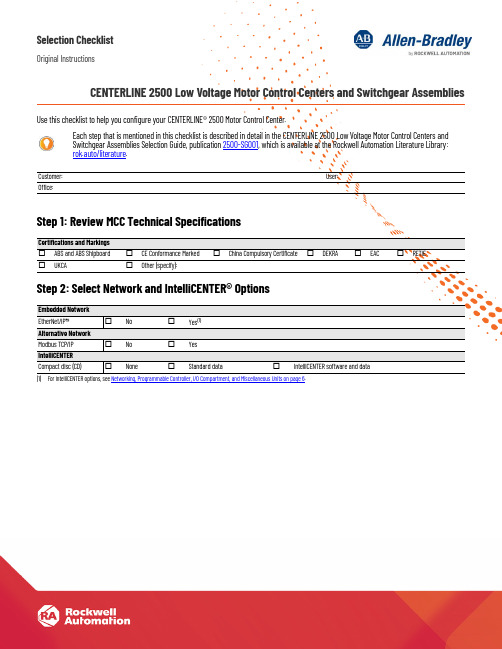
Selection ChecklistOriginal InstructionsCENTERLINE 2500 Low Voltage Motor Control Centers and Switchgear Assemblies Use this checklist to help you configure your CENTERLINE® 2500 Motor Control Center.Step 1: Review MCC Technical SpecificationsStep 2: Select Network and IntelliCENTER® OptionsEach step that is mentioned in this checklist is described in detail in the CENTERLINE 2500 Low Voltage Motor Control Centers andSwitchgear Assemblies Selection Guide, publication 2500-SG001, which is available at the Rockwell Automation Literature Library:rok.auto/literature.Customer:User:Office:Certifications and Markings☐ABS and ABS Shipboard☐CE Conformance Marked☐China Compulsory Certificate☐DEKRA☐EAC☐RETIE☐UKCA☐Other (specify):Embedded NetworkEtherNet/IP™☐No☐Yes(1)(1)For IntelliCENTER options, see Networking, Programmable Controller, I/O Compartment, and Miscellaneous Units on page6.Alternative NetworkModbus TCP/IP☐No☐YesIntelliCENTERCompact disc (CD)☐None☐Standard data☐IntelliCENTER software and data2Rockwell Automation Publication 2500-SR001J-EN-P - September 2022CENTERLINE 2500 Low Voltage Motor Control Centers and Switchgear Assemblies Selection ChecklistStep 3: Select StructureStep 4: Select Power SystemsStructure Enclosure rating ☐IP 42 (standard)☐IP 54☐IP 20ArcShield™ (IEC/TR 61641)☐No (standard)☐Yes Forms of internal separation ☐3b (standard)☐2b ☐4b Type 5☐4b Type 7Mounting configuration ☐Single front (standard)☐Double front (back-to-back)☐Add to existingVertical wireway width ☐200 mm (700 mm total column width)☐300 mm (800 mm total column width)☐400 mm (900 mm total column width)☐500 mm (1000 mm total column width)Depth☐600 mm (single front)☐800 mm (single front)☐1200 mm (double front or back-to-back)☐1600 mm (double front or back-to-back)Ambient temperature, max _________ °CAltitude__________________ metersExternal paint ☐RAL7032 Pebble Gray (standard)☐Other (specify):(1)(1)To provide a more detailed description, use the Notes section that begins on page 8.Internal paint☐Z275 galvanized steel (standard)☐High visibility gloss white☐Other (specify):(1)Master Nameplate☐No☐Yes (up to five lines; 40 characters maximum per line)Line 1:Line 2:Line 3:Line 4:Line 5:Options☐Space heater with thermostat☐Cable supports for vertical wireways ☐Other (specify):(1)Incoming Power Line voltage ☐380V ☐400/415V ☐440/460/480V ☐525/575V☐690V Frequency ☐50 Hz☐60 HzSystem power ☐Delta ☐Grounded Delta☐Grounded wye ☐Grounded wye with impedanceAvailable fault current _________ kABusWithstand/fault ratings ☐50 kA for 1 second ☐50 kA for 3 seconds☐ 65 kA for 1 second ☐ 80 kA for 1 second ☐ 100 kA for 1 secondHorizontal power bus rating☐800 A ☐1250 A ☐1600 A ☐2000 A☐2500 A ☐3200 A ☐4000 A Horizontal power bus material ☐Copper, tin plated (standard)☐Copper, unplated Neutral bus☐None (standard)☐Full rated☐Half ratedVertical distribution bus rating☐300 A (provides 600 A capacity)☐600 A (provides 1200 A capacity)Vertical distribution bus material ☐Copper, tin plated (standard)☐Copper, unplatedStab openingsNOTE: Automatic shutters are included as standard.Protective Earth (PE)Horizontal PE location ☐Bottom (standard)Vertical PE conductor for withdrawable units☐Copper, unplated (standard)☐Copper, tin plated Vertical PE conductor for customer load ☐Copper, unplated (standard)☐Copper, tin platedRockwell Automation Publication 2500-SR001J-EN-P - September 20223CENTERLINE 2500 Low Voltage Motor Control Centers and Switchgear Assemblies Selection ChecklistStep 5: Select Unit DesignsStep 6: Select Unit TypesUnit Configuration–General Outgoing cable access ☐Top☐BottomUnit type☐Standard withdrawable☐Fixed mount☐Withdrawable with SecureConnect™Nameplates (white with black lettering)☐Engraved acrylic (standard)Unit Control Power Voltage☐24V DC☐110/115/120V AC☐220/230/240V AC Source☐Central control power transformer (standard)☐Line to neutral ☐Remote control power sourceIndividual control transformer:☐75VA ☐150VA☐250VA☐Other (specify):(1)(1)To provide a more detailed description, use the Notes section that begins on page 8.IMPORTANT: For disconnect selections, see the Main Incoming, Feeder, DOL/DOLR, and Starter Unit sections in Section 6.Control terminal blocks location☐Vertical wireway (standard)☐Top horizontal wireway Control terminal blocks☐Push-in type (standard)☐Screw typeMain Incoming Unit Ampere rating _________ AMain incoming types☐Air circuit breaker (ACB) (standard)☐Molded case circuit breaker (MCCB) (standard)☐Main lug (MLO)Main incoming locations☐Left☐Center ☐RightEntry:☐Top☐Bottom Incoming configuration:☐Single main ☐Dual main ☐Main-tie-mainCircuit breaker type☐3-pole☐4-poleNumber of cables per phase: _________Cable size: __________________Main breaker accessories☐Shunt-trip☐Auxiliary contacts QTY:_________☐Electrical charging device ☐Closing release ☐Shunt release ☐Undervoltage release☐Motorized operation☐Thermography ☐Precision metering %:_________Communication:☐EtherNet/IP ☐Other (specify):(1)(1)To provide a more detailed description, use the Notes section that begins on page 8.The Step 6 table continues on the next page.Protection☐LSI (standard)☐LI☐LSIG☐DIP switch ☐Digital touch screen ☐Automatic transfer☐Generator sync☐Load-shedding (tie)4Rockwell Automation Publication 2500-SR001J-EN-P - September 2022CENTERLINE 2500 Low Voltage Motor Control Centers and Switchgear Assemblies Selection ChecklistStep 6: Select Unit Types (continued)The DOL/DOLR Options and Accessories section, and the Step 6 table continue on the next page.Feeder Unit (1)Types ☐Air circuit breaker (ACB) (standard)☐Molded case circuit breaker (MCCB) (standard)Disconnect means☐Circuit breaker, thermal magnetic (standard)☐Circuit breaker, electronic ☐Fused disconnectFuse type:☐DIN☐BS88Options☐Auxiliary contacts QTY:_________☐Electrical charging device ☐Closing release ☐Shunt release☐Motorized operation☐Thermography☐Precision metering %:_________DOL/DOLR Starter Units (1)(1)Supply a separate load list, which is on page 7. For unique applications, copy this DOL/DOLR section to the Notes section on page 8, and complete as needed.Disconnect means ☐Circuit breaker (standard)☐Fused disconnect Fuse type:☐DIN☐BS88Electronic overload relay type ☐E100™☐E300™Duty rating ☐AC3 (standard)☐AC4Protection☐Type 2 (standard)☐Type 1Functional Safety (2)(2)For information regarding functional safety with a LVMCC, see the CENTERLINE Low Voltage Motor Control Centers Functional Safety Application Technique, publication MCC-AT007.☐No (standard)☐Yes - If yes, select category.☐ Category 1 with Interposing Relay ☐Category 1 with NO Interposing Relays ☐ Category 2 with Minotaur Safety Monitoring Relay☐Category 3 with Interposing Relays ☐ Category 3 with NO Interposing Relays ☐Category 3 with Guardmaster Safety Monitoring Relay☐ Category 3 with Minotaur Safety Monitoring RelayDOL/DOLR Options and AccessoriesPilot lights (light-emitting diode [LED])☐No (standard)☐Yes - If yes, text on legend plate:☐On ☐Forward ☐Off ☐Reverse☐Fault ☐Other (specify):(3)(3)To provide a more detailed description, use the Notes section that begins on page 8.Push buttons☐No (standard)☐Yes - If yes, text on legend plate:☐On ☐Off☐Reset ☐Emergency☐Other (specify):(2)Selector switch ☐No (standard)☐2-position☐3-positionFunction: ______________________________________________________________________________________________________Reset☐Internal (standard)☐External–door mountedE100 remote Indication display☐No (standard)☐YesIf yes, display type:☐Without reset button☐With reset button E300 control stations ☐No (standard)☐Yes If yes, station type:☐Control☐DiagnosticRockwell Automation Publication 2500-SR001J-EN-P - September 20225CENTERLINE 2500 Low Voltage Motor Control Centers and Switchgear Assemblies Selection ChecklistStep 6: Select Unit Types (continued)The Step 6 table continues on the next page.DOL/DOLR Options and Accessories (continued)Auxiliary contactsStarter:☐Normally open QTY:_________☐Normally closed QTY:_________Circuit breaker:☐Normally open QTY:_________☐Normally closed QTY:_________Misc. options ☐Ground fault ☐Voltage monitoring ☐Other (specify):(1)(1)To provide a more detailed description, use the Notes section that begins on page 8.Soft Starter Units (2)(2)Supply a separate load list, which is on page 7. For unique applications, copy the Soft Starter Units section to the Notes section that begins on page 8, and complete as needed.Types ☐SMC™ Flex (standard)☐Other (specify):(1)Connection☐Line☐DeltaDisconnecting means☐Circuit breaker (standard)☐Fused (rotary operator)SMC Options and AccessoriesPilot lights (LED)☐No (standard)☐Yes - If yes, text on legend plate:☐On ☐Forward ☐Fault☐Off ☐Reverse ☐Other (specify):(2)Push buttons☐No (standard)☐Yes - If yes, text on legend plate:☐On ☐Emergency ☐Reset☐Off☐Other (specify):(2)Selector switch☐No (standard)☐2-position ☐3-positionFunction: ______________________________________________________________________________________________________Human machine interface (HMI)☐No (standard)☐LCD display, full numeric keypad ☐LCD display, programmer only Starting mode ☐No (standard)☐Pump control ☐Braking controlOthers (2)PowerFlex® AC Variable Frequency Drive (VFD) Units (3)(3)Copy this section to the Notes section that begins on page 8, and complete for each unit needed.PowerFlex model☐523☐525☐753☐755☐755 TL/TR Duty rating ☐Normal ☐HeavyAmpere rating A: _________Kilowatt rating kW: _________Disconnecting means ☐Circuit breaker (standard) ☐Fused (rotary operator)Fuse type: ______________☐Fused not suppliedHandle operator☐Rotary operator (standard)☐Flange operator (2 module, min)6Rockwell Automation Publication 2500-SR001J-EN-P - September 2022CENTERLINE 2500 Low Voltage Motor Control Centers and Switchgear Assemblies Selection ChecklistStep 6: Select Unit Types (continued)PowerFlex Unit Options and Accessories (continued)Pilot lights (LED)☐No (standard)☐Yes - If yes, text on legend plate:☐On ☐Forward ☐Fault ☐Off ☐Reverse ☐Other (specify):(1)(1)To provide a more detailed description, use the Notes section that begins on page 8.Push buttons☐No (standard)☐Yes - If yes, text on legend plate:☐On☐Emergency ☐Reset☐Off☐Other (specify):(2)Selector switch ☐None (standard)☐2 position ☐3 positionFunction: ______________________________________________________________________________________________________Human machine interface (HMI)☐LCD display, full numeric keypad ☐LCD display, programmer onlyBraking mode ☐Pump control ☐Braking control Reactor type ☐Line ☐Load EMC filter☐No ☐Yes (standard)Functional Safety (2)(ISO 13849-1)(2)For information regarding functional safety with a LVMCC, see the CENTERLINE Low Voltage Motor Control Centers Functional Safety Application Technique, publication MCC-AT007.☐No (standard)☐Yes - PowerFlex 755/753 If yes, select category.☐Category 1…3 with20-750-S Safe Torque Off☐Category 1…3 with 20-750-S Safe TorqueOff plus GSR-DI Safety Monitoring Relay ☐Category 1…3 with 20-750-S Safe Torque Off plus GSR-DI and GSR-EMD☐Category 1…3 with 20-750-S3 Integrated Safe Torque Off (PowerFlex 755 only)☐Category 1…4 with 20-750-S4 Integrated SafetyFunctions(PowerFlex 755 only)☐Category 1…3 with 20-750-S Safe Torque Off plus MSR127 Safety Monitoring Relay☐Category 1…3 with 20-750-S Safe Torque Off plusMSR138DP Safety Monitoring Relays☐Yes - PowerFlex 525If yes, select category.☐Category 1…3 with Hardwired STO☐Category 1…3 with GSR-DI Safety Monitoring Relay, Hardwired STO ☐Category 1…3 with GSR-DI and GSR-EMD Safety Monitoring Relays, Hardwired STO☐Category 1…3 with MSR127 Safety Monitoring Relay, Hardwired STO☐Category 1…3 with MSR138DP Safety Monitoring Relays, Hardwired STO Networking, Programmable Controller, I/O Compartment, and Miscellaneous Units EtherNet/IP managed switch ☐Stratix® 5700 Full firmware ☐Stratix 5700 Lite firmware Network linking devices ☐Ethernet to DeviceNet® device ☐Ethernet to PROFIBUS device ☐Other (specify):(2)EtherNet/IP power supply ☐Primary (standard)☐Redundant ☐Backup I/O compartments ☐FLEX™ I/O system☐POINT I/O™ system☐Other (specify):(2)Miscellaneous Units Programmable controllers Number of slots:_________Power supply:____________________________________Describe what you need:(2)Extra space for future units Describe what you need:(2)Distribution panels☐ 1 pole QTY:_________☐ 3 pole QTY:_________☐2 pole without residual current detection QTY:_________☐2 pole with residual current detection QTY:_________List the circuit loads needed:(2)CENTERLINE 2500 Low Voltage Motor Control Centers and Switchgear Assemblies Selection Checklist Step 6: Select Unit Types (continued)Load ListUnit Type (For example, DOL, DOLR, SMC, VFD, heater…)Unit ID Rating ModuleSize Misc. NoteRockwell Automation Publication 2500-SR001J-EN-P - September 202278Rockwell Automation Publication 2500-SR001J-EN-P - September 2022CENTERLINE 2500 Low Voltage Motor Control Centers and Switchgear Assemblies Selection ChecklistNotesThe Notes table continues on the next page.Topic and Page(For example, PowerFlex PilotLights, page 6)NotesRockwell Automation Publication 2500-SR001J-EN-P - September 20229CENTERLINE 2500 Low Voltage Motor Control Centers and Switchgear Assemblies Selection ChecklistNotes (continued)The Notes table continues on the next page.Topic and Page(For example, PowerFlex PilotLights, page 6)Notes10Rockwell Automation Publication 2500-SR001J-EN-P - September 2022CENTERLINE 2500 Low Voltage Motor Control Centers and Switchgear Assemblies Selection ChecklistNotes (continued)The Notes table continues on the next page.Topic and Page(For example, PowerFlex PilotLights, page 6)NotesRockwell Automation Publication 2500-SR001J-EN-P - September 202211CENTERLINE 2500 Low Voltage Motor Control Centers and Switchgear Assemblies Selection ChecklistNotes (continued)The Notes table continues on the next page.Topic and Page (For example, PowerFlex Pilot Lights, page 6)NotesCENTERLINE 2500 Low Voltage Motor Control Centers and Switchgear Assemblies Selection Checklist Notes (continued)Topic and PageNotes (For example, PowerFlex PilotLights, page6)12Rockwell Automation Publication 2500-SR001J-EN-P - September 2022Rockwell Automation Publication 2500-SR001J-EN-P - September 202213Publication Title Selection ChecklistAdditional ResourcesThese documents contain additional information concerning related products from Rockwell Automation.You can view or download publications at rok.auto/literature .ResourceDescription CENTERLINE 2500 Low Voltage Motor Control Centers Installation Instructions, publication 2500-IN001Provides instructions to receive, handle, install, commission, maintain, remove, and store CENTERLINE® 2500 motor control centers.CENTERLINE Low Voltage Motor Control Centers Functional Safety Application Technique, publication MCC-AT007.Describes a standardized implementation of safety functions that combine CENTERLINE Low Voltage Motor Control Centers (LVMCC) with a variety of safety-related products.IEC Contactor Specifications Technical Data, publication 100-TD013Provides technical specifications for the Bulletin Nos. 100 and 104 IEC contactors.Molded Case Circuit Breakers Selection Guide, publication 140G-SG001Provides an overview of molded case circuit breakers (MCCBs), and the various frame sizes of the Bulletin 140G breakers that Allen-Bradley offers.Motor Protection Circuit Breaker and Motor Circuit Protector Specifications Technical Data, publication 140M-TD002Provides technical specifications for motor protection circuit breakers, and the various frame sizes of the Bulletin 140M breakers that Allen-Bradley offers.E300/E200 Electronic Overload Relay Technical Data, publication 193-TD006Provides technical specifications for the Allen-Bradley® E300 and E200 overload relays for motor control applications, and for the three modules of each relay.E100 Electronic Overload Relay Specifications Technical Data, publication 193-TD013Provides technical specifications for the Allen-Bradley E100 electronic overload relays for motor control applications.PowerFlex 750-series AC Drives Technical Data, publication 750-TD001Provides technical specifications for the 750-series AC drives in various frame sizes, and in wall mount, floor mount, and roll out models.ControlLogix System Selection Guide, publication 1756-SG001Provides an overview of the various 1756 Series ControlLogix systems, which provide discrete, drives, motion, process, and safety control.Stratix 5700 Industrial Ethernet Switch Profile, publication ENET-PP005Provides an overview of the features and benefits of the Stratix 5700 industrial Ethernet switch.EtherNet/IP Network Devices User Manual, publication ENET-UM006Describes how to configure and use EtherNet/IP devices to communicate on the EtherNet/IP network.Ethernet Reference Manual, publication ENET-RM002Describes basic Ethernet concepts, infrastructure components, and infrastructure features.System Security Design Guidelines Reference Manual, publication SECURE-RM001Provides guidance on how to conduct security assessments, implement Rockwell Automation products in a secure system, harden the control system, manage user access, and dispose of equipment.Industrial Components Preventive Maintenance, Enclosures, and Contact Ratings Specifications, publication IC-TD002Provides a quick reference tool for Allen-Bradley industrial automation controls and assemblies.Industrial Automation Wiring and Grounding Guidelines, publication 1770-4.1Provides general guidelines to install a Rockwell Automation® industrial system.Product Certifications website, rok.auto/certifications .Provides declarations of conformity, certificates, and other certification details.Publication 2500-SR001J-EN-P - September 2022Supersedes Publication 2500-SR001I-EN-P - April 2021Copyright © 2022 Rockwell Automation, Inc. All rights reserved. Printed in the U.S.A.Rockwell Automation SupportUse these resources to access support information.Documentation FeedbackYour comments help us serve your documentation needs better. If you have any suggestions on how to improve our content, complete the form at rok.auto/docfeedback .Technical Support CenterFind help with how-to videos, FAQs, chat, user forums, Knowledgebase, and product notification updates.rok.auto/support Local Technical Support Phone NumbersLocate the telephone number for your country.rok.auto/phonesupport Technical Documentation CenterQuickly access and download technical specifications, installation instructions, and user manuals.rok.auto/techdocs Literature LibraryFind installation instructions, manuals, brochures, and technical data publications.rok.auto/literature Product Compatibility and Download Center (PCDC)Download firmware, associated files (such as AOP, EDS, and DTM), and access product release notes.rok.auto/pcdc Rockwell Automation maintains current product environmental compliance information on its website at rok.auto/pec .Allen-Bradley, ArcShield, CENTERLINE, ControlLogix, E100, E300, expanding human possibility, FLEX I/O, IntelliCENTER, POINT I/O, PowerFlex, Rockwell Automation, Rockwell Software, SecureConnect, SMC, and Stratix are trademarks of Rockwell Automation, Inc.DeviceNet and EtherNet/IP is a trademark of ODVA, Inc.Trademarks not belonging to Rockwell Automation are property of their respective companies.Rockwell Otomasyon Ticaret A.Ş. Kar Plaza İş Merkezi E Blok Kat:6 34752, İçerenköy, İstanbul, Tel: +90 (216) 5698400 EEE Yönetmeli ğine Uygundur。
iMCC(智能马达控制中心) 一切尽在掌握

Based on TeSys U, the best balance between functionalities and investment
MotorSys Multifunction
■ ■ ■ ■ ■ ■ ■ ■ ■ ■ ■ ■ ■ ■ ■ ■ ■ ■ ■
MotorSys Advanced
■ ■ ■ ■ ■ ■ ■
■
■
■
■
■
■
■
■
■
■
■
■
■
■
rSys Classic
■
■ Several control units available according to application requirements: Multifunction, Advanced, Basic ■ Intelligent protection based on current measurement: over/under load, stalling, long starting, etc… ■ Transmitting the most practical monitoring information to SCADA ■ Control modes: DOL and reversing motors ■ “All-in-one” solution for motors up to 15kW, total coordination
- 1、下载文档前请自行甄别文档内容的完整性,平台不提供额外的编辑、内容补充、找答案等附加服务。
- 2、"仅部分预览"的文档,不可在线预览部分如存在完整性等问题,可反馈申请退款(可完整预览的文档不适用该条件!)。
- 3、如文档侵犯您的权益,请联系客服反馈,我们会尽快为您处理(人工客服工作时间:9:00-18:30)。
集成化的智能马达控制中心
Allen Bradley CENTERLINE® 2500 MCC智能低压柜-节能之窗
在全球能源极速紧缺的时代,高效率利用有限的能源是不二的选择,但是,一个
重要的前提,你知道你的能源都消耗在哪些生产工艺环节吗?你知道你下一个
节能项目该从何下手吗?你有足够的数据支持你的推论吗?罗克韦尔自动化A-B
CENTERLINE® 2500智能低压柜提供了智能解决方案及所需的硬件,通过集成架构
及网络能完整地“透视”你对于能耗分析所需的相关数据,包括最底层设备的数
据,让你轻松地利用完整的数据对于工厂的短期改造及长期扩建做出正确有依据
的决策。
罗克韦尔自动化A-B CENTERLINE® 2500是新一代的IEC智能低压柜,延用了
Allen Bradley北美NEMA标准的精干耐用基础结构设计(CENTERLINE® 2100)完全
符合IEC市场的需求。
罗克韦尔自动化A-B拥有超过百年的低压马达控制经验,
CENTERLINE® 2100 NEMA低压柜在北美更是多年来占有市占率第一的市场领先地
位,更于1999年为全球第一个厂家推出了智能化的低压柜。
智能低压柜的概念
在北美从此被广泛的接受及应用也造福了广大的客户群在生产上的便利。
智能低压柜的关键优点
智能低压柜除了能够为节能提供重大工厂改进决策的准确数据及讯息,其另一优点是能在运行中的生产线要发生故障前提前预报警让你实时解决即将要发生的问题进而大大的提升生产效率及降低生产线停产的风险及成本。
智能低压柜的综合成本概念
单单以硬件成本计算,智能低压柜明显的会比传统的低压柜高,原因不外乎是因为拥有了全系列的智能器件。
但是对于最终投资方来说智能低压柜的成本往往是降低的,关键就在于智能低压柜的综合成本优势。
以智能的网络来代替传统的硬接线,大量的铜制硬接线省略了及现场的施工调试所需的人力物力大大的减少了,以及大量的I/O模块也省略了,此外,后期的现场维护人员及需求则大规模的节约因为所有的设备监视都在主控室里就能够实现。
其实最关键的成本是现场停机工厂停产所造成的损失,智能低压柜能帮助你有效的减低非预期的生产风险。
许多实际案例说明了非预期的生产停机造成的成本远远大于前期设备的投资。
A-B CENTERLINE® 2500与市面上所谓的智能低压柜的关键差异
只要是有吸引力的新产品,厂家们为了竞争及抢市场争先恐后的抄袭新技术已经相当普遍,最后都是以打价格战收场,智能低压柜也不例外。
罗克韦尔自动化在1999年推出了全球第一套智能低压柜,此后有无数的厂家试着用最低廉成本的方式来达到所谓的智能低压柜技术。
这些类型的低压柜产品往往用户们买的时候觉得捡到了便宜,但在使用上却碰到了种种的问题进而对智能低压柜失去了信心。
智能低压柜的好坏关键,从罗克韦尔自动化的角度来看不外乎是两点:网络的可靠性及动力的安全性。
A-B CENTERLINE® 2500是标准的订制化产品,其优越的“智能柜体”性能针对每种不同的现场应用都有标准的设计及参数要求。
这些标准设计都是通过了罗克韦尔自动化在美国密尔瓦基的研发总部重复严格测试及验证的结晶,确保了整体设计的可靠性及安全性。
再经由A-B IntelliCENTER®专用智能低压柜软件的支持,完整的为用户提供了全套智能解决方案。
在国家标准中也有明确的定义智能低压柜的要求(GB/T 7251.8)。
此标准明确了网络电缆及动力电缆的铺设结构要求及监控软件的必要性。
许多厂家都只是简单的使用了部份的智能器件再将网络铺设在传统的低压柜中。
在应用设计当中也是以节省空间及成本为前提因而种下了网络的断线、干扰及器件使用过热故障的隐忧。
许多潜在问题是在前期调试无法体现的,等发现时常常都是在生产已受到严重影响之后。
罗克韦尔自动化对CENTERLINE® 2500智能低压柜质量的保证
除了上述从产品研发的质量保证,罗克韦尔自动化对其生产的要求也以同一标准看待。
所有的A-B CENTERLINE® 2500都是由罗克韦尔自动化独资的工厂生产已对其生产工艺及整串供应链做严格的把关。
在中国,A-B CENTERLINE® 2500只有在罗克韦尔自动化的独资上海金桥工厂生产,完全没有贴牌、生产及供应链失控的隐忧为用户提供了高质量的保证。
智能低压柜的优点在理论上是有目共睹的,其中包括了对短期、长期节能减排的铺垫,生产不停机的预报警功能,有节约综合成本的优势。
但是在实际执行上,用户还是要慎选厂家及柜型,以国家标准(GB/T 7251.8)对智能低压柜的要求为前提来做评估,进而对工厂的长远可靠安全运行打下稳固的基础。
.
智能低压柜定义
智能低压柜的关键元素
您知道什么是真正的智能低压柜吗?基于智能低压柜国家标准GB/T 7251.8的规定,其关键要素有:• 要求全系列智能元器件,如智能马达保护器;• 要求低压柜内置现场总线,如DeviceNet ,Profi bus ;• 要求专门设计的智能柜体结构,如要求通讯及控制电缆与 动力电缆完全隔离;
•
要求具备专用的监控软件,如IntelliCENTER®。
综合成本概念
智能低压柜综合成本
智能低压柜由于采用了总线技术,结合其无比优越的预诊断及远程监控功能,从而最大限度地避免了非预期的生产风险。
具体来说:
• 缩短设计周期,减少设计工作量;• 大量减少I/O 模块;
• 减少大量的硬接线工作,减少劳动力开支;• 采用专用的设计软件,减少设计错误;• 大量节省现场安装及调试费用;• 大量节省后期维护费用。
智能马达控制
智能马达控制
罗克韦尔自动化具有超过百年的马达控制经验,在90年代全球第一个推出智能马达控制中心,通过智能马达控制给客户带来的好处有:• 强大的预诊断及预报警功能,大大降低生
产的风险;• 综合成本的节约;
• 通过集中控制和管理,极大地方便和减少
现场的维护。
智能柜体结构
智能柜体独特结构
为了保证智能低压柜通讯的可靠性、稳定性,其专用的智能柜体结
结构特性
Publication 2500-PP002A-ZH-P July 2010 Copyright 2010 Rockwell Automation Inc. Printed in CHINA.。