摆块夹具说明书
JBC 微夹具说明书

Micro TweezersRef. PA120-B2C120 Cartridges (Required but not supplied)Control UnitStand Ref. PA-SDManual ................................................ 1 unit Ref. 0019081Packing ListThe following items should be included:Micro Tweezers ...................................... 1 unit Ref. PA120-B Micro Tweezers Ref. PA120-BFeatures32. Inserting3. Rotational and Vertical aligningChanging cartridgesUnlock the manual fixing and remove the cartridge. If is necessary, you can use a flat pliers (Ref. PLR-195).1. RemovingInsert the cartridge as far as the mark for a proper connection. Before inserting, make sure the cartridges are clean to ensure the proper function of the rotational aligning.MarkThe PA120-B Micro Tweezers works with C120 cartridge range.Find the model that best suits your soldering needs in C120-004C120-001C120-005C120-009C120-010Compatible cartridgesFor a rotational alignment, turn the cartridges in any direction through the wheels.Don´t forget to lock the manual fixing.!The tail wheel guarantees that the cartridges are equally aligned with vertical symmetry.This product should not be thrown in the garbage.In accordance with the European directive 2002/96/EC, electronic equipment at the end of their life must be collected and returned to an authorized recycling facility.Manual in other languages available on our websiteWarrantyJBC’s 2 year warranty covers this equipment against all manufacturing defects, including the replacement of defective parts and labour.Warranty does not cover product wear or misuse. In order for the warranty to be valid, equipment must be returned, postage paid, to the dealer where it was purchased. Please register your product warranty within 30 days of purchase in /productregistration.Specifications0019081-0118- Weight:100 g (0.22 lb)- Max. power per cartridge:40WComplies with CE standards.ESD protected.。
夹具设计说明书 (3)
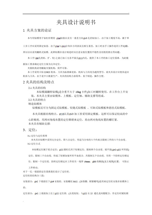
夹具设计说明书1 夹具方案的论证本专用钻模用于钻杠杆臂的钻削以及另一垂直方向13孔的钻加工。
由于加工精度不高,属于单工步工序应采用固定钻套。
由于与分布在小同表而且相互垂直,加工时由手工操作连同工件起翻,所以以应采用翻转式钻模。
此种钻模在设计制造时应注意安装位置的平稳性及切屑的排出等问题。
本工序(孔的钻、扩、铰)之前已加工完各平面且内孔,提供了本工序的加工定位基准。
为此根据加工要求确定定位方案为完伞定位。
夹紧机构采用螺旋夹紧机构,简甲可靠。
本工序采用立钻Z5025机床,刀具为标准麻花钻。
机床与刀具均为通用型号,故夹具设计应使其适应机床与刀具,由于是中小批量生产,夹具的结构力求简单,易于制造,操作方便。
2夹具的结构及特点2.1夹具的结构本钻模属翻转钻模(适合重不大于10kg小件)加工时翻转使用,在工作台上不安装,本夹具主要由钻模体、上模板、定位轴、辅助支撑等组成。
2.2夹具的特点铸造钻模体钻模板还可分为固定式钻模板、铰链式钻模板、可卸式钻模板和悬挂式钻模板。
本夹具根据结构特点,以及13加工皆采用固定模板。
这样可以保证较高的中心距精度,用两对角线布置的定位锥销来定位,再由两对角线布置的螺钉紧。
本夹具有辅助支撑:3.定位:3.1定位与定位原理本夹具在钻模中采用完全定位,即六点定位,用适当分布的六个约束点限制工件的六个自由度。
3.2定位方式本钻模定位属于组合定位:22圆柱孔用于短销定位,限制两个自由度,端平面(42-22环形面)定位,限制三个自由度,形成了短销加宽环形平血组合,共限制五个自由度。
另用一个防转定位销定位,限制一个定位度。
防转定位销定在工件的另一端厚10mm,lO的侧面(见左视图)位置,可防止工件转动。
对于一孔一端面的定位基准我们设计了定位柱。
定位柱的结构分三段:安装部分:42下端面往下16安装柱,安装螺纹M12。
(加垫圈、锁紧螺母)是用来定位柱安装在钻模体上的。
定位部分:42上端面加上往上22定位颈。
LGW 2-Finger 角度夹具说明书

728Sizes 10 .. 40Weight0.042 kg .. 0.845 kg Gripping moment 0.22 Nm .. 8.65 Nm Opening angle per finger 20°Workpiece weight0.06 kg .. 1.1 kgApplication exampleHandling module for discharging inspection components from the assembly belt2-Finger Angular Gripper LGW 16FST-S 10-61 Mini-slide729Function optimized gipper type for maximum cost effectivenessStable cinematicsfor high power transmission and synchronized gripping Matching SCHUNK C-slot switch for a process reliable position interrogationHard-anodized or hardened functional components for long lifetimeCentering sleevesfor an repeat accurate exchange of grippers and fingers Compact dimensionsfor minimized disturbing contoursUniversal Angular Gripper for small to medium-sized workpieces with excellent cost/performance ratioUniversal Angular GripperArea of applicationClean surrounding for example an assembly areaYour advantages and benefitsGeneral information on the seriesWorking principledouble actuated, guided cinematics Housing materialAluminum alloy, hard-anodized Base jaw materialAluminum alloy, hard-anodizedActuationPneumatic, with filtered compressed air (10 µm): Dry, lubricated or non-lubricated Pressure medium: Requirements on quality of the compressed air according to DIN ISO 8573-1: 6 4 4.Warranty 24 monthsScope of deliverySwivel fittings, centering sleeves, assembly and operation manualwith manufacturer’s declaration730Housingweight-optimised through application of hard-anodized, high-strength aluminum alloy Base fingersfor the connection of workpiece-specific gripper fingersKinematicsprecise gear for centric gripping Gripping force safety device mechanic gripping force maintenance for O.D. grippingCentering and mounting possibilities for assembly of the gripper to a base areaand at the long sideThe piston is moved up or down by means of compressed air. The kinematics use the lever system to convert the vertical motion into the synchronous, rotating movement of the base jaws.Function descriptionMonitoring with a SCHUNK MMS 22 or RMS 22 sensor is not possible. The use of the recomended sensors MZN and RZN is not compulsory.Options and special informationSectional diagram731Gripping momentis the arithmetic total of gripping moments for each claw jaw.Finger lengthThe finger length is measured from the upper edge of the gripper housing in direction to the main axis. If the max. admissible finger length is exceeded, the speed of motions of the jaws has to be reduced and/or the opening angle has to be diminished,as it is done with heavy fingers. The service life of the gripper can shorten. Repeat accuracyis defined as the spread of the limit position after 100 consecutive strokes.Workpiece weightThe recommended workpiece weight is calculated for a force-type connection with a coefficient of friction of 0.1 and a safety factor of 2 against slippage of theworkpiece on acceleration due to gravity g. Considerably heavier workpiece weights are permitted with form-fit gripping.Closing and opening timesClosing and opening times are purely the times that the base jaws or fingers are in motion. Valve switching times, hose filling times or PLC reaction times are not included in the above times and must be taken into consideration when determining cycle times.General information on the seriesCentering sleevesFittingsMZN/RZN magnetic switchesSDV-P pressure maintenance valvesV sensor distributorsAccessoriesKV/KA sensor cablesFor the exact size of the required accessories, availability of this size and the designation and ID, please refer to the additional views at the end of the size in question. You will find more detailed information on our accessory range in the “Accessories” catalog section.Technical dataFinger loadMoments and forces apply per base jaw and may occursimultaneously. If the max. permitted finger weight isexceeded, it is imperative to throttle the air pressure sothat the jaw movement occurs without any hitting orbouncing. Service life may be reduced.Gripping force, O.D. grippingDescription LGW 10LGW 10-ASID03129500312951 Opening angle per jaw[°]20.020.0 Opening angle per jaw up to[°] 2.0 2.0 Closing moment[Nm]0.220.28 Closing moment ensured by spring[Nm]0.06 Weight[kg]0.0420.043 Recommended workpiece weight[kg]0.0850.085 Air consumption per double stroke[cm3]0.70.7 Nominal pressure[bar] 6.0 6.0 Minimum pressure[bar] 2.0 4.0 Maximum pressure[bar]8.0 6.5 Closing time[s]0.020.02 Opening time[s]0.020.03 Max. permitted finger length[mm]25.025.0 Max. permitted weight per finger[kg]0.040.04 IP rating4040 Min. ambient temperature[°C]-10.0-10.0 Température ambiante max.[°C]90.090.0 Repeat accuracy[mm]0.020.02732733Electronic magnetic switches / Reed Switches, for direct mounting Description ID MZN 1-06VPS-KRD 0312990RZN 1-05ZRS-KRD 0312991Two sensors (NO contacts) are required for each gripper, plus extension cables as an option.Main viewsThe drawing shows the gripper in the basic version with closed jaws, the dimensions do not include the options described below.A,a Main/direct connection, gripper opening B,b Main/direct connection, gripper closing ᕃGripper connection ᕄFinger connectionᕍᕚClamping reserve per fingerThe SDV-P pressure maintenance valve can also be used (see “Accessories”catalog section) for I.D. or O.D. gripping as an alternative or in addition to the spring-loaded, mechanical gripping force safety device.Sensor SystemExtension cables for proximity switches/magnetic switches Description ID KA BG08-L 3P-0300-PNP 0301622KA BW08-L 3P-0300-PNP 0301594KA BW08-L 3P-0500-PNP 0301502KV BW08-SG08 3P-0030-PNP 0301495KV BW08-SG08 3P-0100-PNP 0301496KV BW08-SG08 3P-0200-PNP 0301497Please note the minimum permitted bending radii for the sensor cables, which are generally 35 mm.Technical dataFinger loadMoments and forces apply per base jaw and may occursimultaneously. If the max. permitted finger weight isexceeded, it is imperative to throttle the air pressure sothat the jaw movement occurs without any hitting orbouncing. Service life may be reduced.Gripping force, O.D. grippingDescription LGW 16LGW 16-ASID03129520312953 Opening angle per jaw[°]20.020.0 Opening angle per jaw up to[°] 2.0 2.0 Closing moment[Nm]0.78 1.0 Closing moment ensured by spring[Nm]0.22 Weight[kg]0.0880.091 Recommended workpiece weight[kg]0.190.19 Air consumption per double stroke[cm3] 2.3 2.3 Nominal pressure[bar] 6.0 6.0 Minimum pressure[bar] 2.0 4.0 Maximum pressure[bar]8.0 6.5 Closing time[s]0.030.025 Opening time[s]0.020.03 Max. permitted finger length[mm]32.032.0 Max. permitted weight per finger[kg]0.050.05 IP rating4040 Min. ambient temperature[°C]-10.0-10.0 Température ambiante max.[°C]90.090.0 Repeat accuracy[mm]0.020.02734735Electronic magnetic switches / Reed Switches, for direct mounting Description ID MZN 1-06VPS-KRD 0312990RZN 1-05ZRS-KRD 0312991Two sensors (NO contacts) are required for each gripper, plus extension cables as an option.Main viewsThe drawing shows the gripper in the basic version with closed jaws, the dimensions do not include the options described below.A,a Main/direct connection, gripper opening B,b Main/direct connection, gripper closing ᕃGripper connection ᕄFinger connectionᕍᕚClamping reserve per fingerThe SDV-P pressure maintenance valve can also be used (see “Accessories”catalog section) for I.D. or O.D. gripping as an alternative or in addition to the spring-loaded, mechanical gripping force safety device.Sensor SystemExtension cables for proximity switches/magnetic switches Description ID KA BG08-L 3P-0300-PNP 0301622KA BW08-L 3P-0300-PNP 0301594KA BW08-L 3P-0500-PNP 0301502KV BW08-SG08 3P-0030-PNP 0301495KV BW08-SG08 3P-0100-PNP 0301496KV BW08-SG08 3P-0200-PNP 0301497Please note the minimum permitted bending radii for the sensor cables, which are generally 35 mm.Technical dataFinger loadMoments and forces apply per base jaw and may occursimultaneously. If the max. permitted finger weight isexceeded, it is imperative to throttle the air pressure sothat the jaw movement occurs without any hitting orbouncing. Service life may be reduced.Gripping force, O.D. grippingDescription LGW 25LGW 25-ASID03129540312955 Opening angle per jaw[°]20.020.0 Opening angle per jaw up to[°] 2.0 2.0 Closing moment[Nm] 3.2 4.1 Closing moment ensured by spring[Nm]0.9 Weight[kg]0.250.255 Recommended workpiece weight[kg]0.50.5 Air consumption per double stroke[cm3]9.09.0 Nominal pressure[bar] 6.0 6.0 Minimum pressure[bar] 2.0 4.0 Maximum pressure[bar]8.0 6.5 Closing time[s]0.0450.06 Opening time[s]0.040.07 Max. permitted finger length[mm]50.050.0 Max. permitted weight per finger[kg]0.10.1 IP rating4040 Min. ambient temperature[°C]-10.0-10.0 Température ambiante max.[°C]90.090.0 Repeat accuracy[mm]0.020.02736737Electronic magnetic switches / Reed Switches, for direct mounting Description ID MZN 1-06VPS-KRD 0312990RZN 1-05ZRS-KRD 0312991Two sensors (NO contacts) are required for each gripper, plus extension cables as an option.Main viewsThe drawing shows the gripper in the basic version with closed jaws, the dimensions do not include the options described below.A,a Main/direct connection, gripper opening B,b Main/direct connection, gripper closing ᕃGripper connection ᕄFinger connectionᕍᕚClamping reserve per fingerThe SDV-P pressure maintenance valve can also be used (see “Accessories”catalog section) for I.D. or O.D. gripping as an alternative or in addition to the spring-loaded, mechanical gripping force safety device.Sensor SystemExtension cables for proximity switches/magnetic switches Description ID KA BG08-L 3P-0300-PNP 0301622KA BW08-L 3P-0300-PNP 0301594KA BW08-L 3P-0500-PNP 0301502KV BW08-SG08 3P-0030-PNP 0301495KV BW08-SG08 3P-0100-PNP 0301496KV BW08-SG08 3P-0200-PNP 0301497Please note the minimum permitted bending radii for the sensor cables, which are generally 35 mm.Technical data Moments and forces apply per base jaw and may occur simultaneously. If the max. permitted finger weight is exceeded, it is imperative to throttle the air pressure so that the jaw movement occurs without any hitting or bouncing. Service life may be reduced.Description LGW 32LGW 32-ASID03129560312957 Opening angle per jaw[°]20.020.0 Opening angle per jaw up to[°] 2.0 2.0 Closing moment[Nm] 5.67.4 Closing moment ensured by spring[Nm] 1.8 Weight[kg]0.460.466 Recommended workpiece weight[kg]0.70.7 Air consumption per double stroke[cm3]16.116.1 Nominal pressure[bar] 6.0 6.0 Minimum pressure[bar] 2.0 4.0 Maximum pressure[bar]8.0 6.5 Closing time[s]0.050.06 Opening time[s]0.0550.07 Max. permitted finger length[mm]62.062.0 Max. permitted weight per finger[kg]0.130.13 IP rating4040 Min. ambient temperature[°C]-10.0-10.0 Température ambiante max.[°C]90.090.0 Repeat accuracy[mm]0.020.02738739Electronic magnetic switches / Reed Switches, for direct mounting Description ID MZN 1-06VPS-KRD 0312990RZN 1-05ZRS-KRD 0312991Two sensors (NO contacts) are required for each gripper, plus extension cables as an option.The drawing shows the gripper in the basic version with closed jaws, the dimensions do not include the options described below.A,a Main/direct connection, gripper opening B,b Main/direct connection, gripper closing ᕃGripper connection ᕄFinger connectionᕍᕚClamping reserve per fingerThe SDV-P pressure maintenance valve can also be used (see “Accessories”catalog section) for I.D. or O.D. gripping as an alternative or in addition to the spring-loaded, mechanical gripping force safety device.Sensor SystemExtension cables for proximity switches/magnetic switches Description ID KA BG08-L 3P-0300-PNP 0301622KA BW08-L 3P-0300-PNP 0301594KA BW08-L 3P-0500-PNP 0301502KV BW08-SG08 3P-0030-PNP 0301495KV BW08-SG08 3P-0100-PNP 0301496KV BW08-SG08 3P-0200-PNP 0301497Please note the minimum permitted bending radii for the sensor cables, which are generally 35 mm.Technical data Moments and forces apply per base jaw and may occur simultaneously. If the max. permitted finger weight is exceeded, it is imperative to throttle the air pressure so that the jaw movement occurs without any hitting or bouncing. Service life may be reduced.Description LGW 40LGW 40-ASID03129580312959 Opening angle per jaw[°]20.020.0 Opening angle per jaw up to[°] 2.0 2.0 Closing moment[Nm]8.611.2 Closing moment ensured by spring[Nm] 2.6 Weight[kg]0.830.845 Recommended workpiece weight[kg]0.850.85 Air consumption per double stroke[cm3]31.031.0 Nominal pressure[bar] 6.0 6.0 Minimum pressure[bar] 2.0 4.0 Maximum pressure[bar]8.0 6.5 Closing time[s]0.0550.06 Opening time[s]0.0550.09 Max. permitted finger length[mm]80.080.0 Max. permitted weight per finger[kg]0.220.22 IP rating4040 Min. ambient temperature[°C]-10.0-10.0 Température ambiante max.[°C]90.090.0 Repeat accuracy[mm]0.020.02740741Electronic magnetic switches / Reed Switches, for direct mounting Description ID MZN 1-06VPS-KRD 0312990RZN 1-05ZRS-KRD 0312991Two sensors (NO contacts) are required for each gripper, plus extension cables as an option.The drawing shows the gripper in the basic version with closed jaws, the dimensions do not include the options described below.A,a Main/direct connection, gripper opening B,b Main/direct connection, gripper closing ᕃGripper connection ᕄFinger connectionᕍᕚClamping reserve per fingerThe SDV-P pressure maintenance valve can also be used (see “Accessories”catalog section) for I.D. or O.D. gripping as an alternative or in addition to the spring-loaded, mechanical gripping force safety device.Sensor SystemExtension cables for proximity switches/magnetic switches Description ID KA BG08-L 3P-0300-PNP 0301622KA BW08-L 3P-0300-PNP 0301594KA BW08-L 3P-0500-PNP 0301502KV BW08-SG08 3P-0030-PNP 0301495KV BW08-SG08 3P-0100-PNP 0301496KV BW08-SG08 3P-0200-PNP 0301497Please note the minimum permitted bending radii for the sensor cables, which are generally 35 mm.。
夹具说明书

课程设计说明书系另寸机电工程系____________________ 专业汽车服务工程__________________ 课程名称《制造技术基础课程设计》学号06121101 ____________________ 姓名黎紫珊________________________ 扌旨导教师杨卓_______________________ 任务名称拨叉夹具设计__________________ 设计时间2014年3-6月_________________2015年6 月17 日目录序言 (1)1.零件的工艺分析及生产类型的确定 (1)2.确定毛坯的制造方法,初步确定毛坯形状 (4)3.工艺规程设计 (6)4.加工阶段的划分 (8)5.工序的集中与分散 (9)6.工序顺序的安排 (10)7.夹具设计 (11)8. 心得体会 (14)9. 参考文献 (15)附表 (16)附图 (18)序言通过这次课程设计,我们不仅对这个学期所学的《机械制造基础》有了更合适呢的理解,同时也是对本专业前面所学的知识的汇总,让我们对这门专业课得以巩固、复习及实用,在理论与实际上有机结合;使我们对相关课有了更深的应用与理解;并为以后的实际工作奠定的坚实的基础。
在这次设计中我们主要是设计 CA614 0车床的拨叉夹具,设计过程中,我们小组成员认真查阅资料,共同完成了这次设计任务。
1.零件的工艺分析及生产类型的确定1.1零件的作用拨叉是一种辅助零件,通过拨叉控制滑套与旋转齿轮的结合,滑套上面有凸块,滑套的凸块插入齿轮的凹位,把滑块和齿轮连在一起,使齿轮带动滑套,滑套带动输出轴,将动力从输入轴传送到输出轴。
拨动拨叉可以控制滑套与不同齿轮的结合与分离,达到换挡的目的。
分析这种动力联接方式可知,车换挡时要减速,这样可以减少滑套与齿轮之间的冲击,延长零件的使用寿命。
该拨叉形状特殊、结构简单,属典型的叉杆类零件。
为实现换档、变速的功能,其叉轴孔与变速叉轴有配合要求,因此加工精度要求较高。
夹具的使用说明

夹具的使用说明夹具是一种用于固定工件的工具,通常用于机械加工、装配和检测等领域。
夹具的作用是将工件固定在特定的位置和角度,以便进行加工或测试。
夹具可以大大提高生产效率和加工精度,因此在工业生产中得到广泛应用。
夹具的种类非常多,根据不同的应用场景和工件形状,可以选择不同类型的夹具。
下面介绍几种常见的夹具类型及其使用说明:1. 机械夹具机械夹具是一种常见的夹具类型,它通过机械力将工件固定在夹具上。
机械夹具通常由夹爪、夹具座和螺旋杆等部件组成。
使用机械夹具时,需要先将工件放在夹具上,然后旋转螺旋杆,使夹爪夹紧工件。
机械夹具适用于各种形状的工件,但需要根据工件的尺寸和形状选择合适的夹具型号。
2. 真空吸盘夹具真空吸盘夹具是一种利用真空吸力将工件固定在夹具上的夹具。
真空吸盘夹具通常由吸盘、真空泵和控制系统等部件组成。
使用真空吸盘夹具时,需要将吸盘放在工件上,然后打开真空泵,产生负压吸附工件。
真空吸盘夹具适用于平面形状的工件,如玻璃、金属板等。
3. 液压夹具液压夹具是一种利用液压力将工件固定在夹具上的夹具。
液压夹具通常由夹爪、液压缸和液压泵等部件组成。
使用液压夹具时,需要先将工件放在夹具上,然后打开液压泵,产生液压力将夹爪夹紧工件。
液压夹具适用于大型工件和需要高精度加工的工件。
4. 磁性夹具磁性夹具是一种利用磁力将工件固定在夹具上的夹具。
磁性夹具通常由磁铁、夹具座和控制系统等部件组成。
使用磁性夹具时,需要将工件放在夹具上,然后打开控制系统,产生磁力将工件吸附在夹具上。
磁性夹具适用于平面形状的工件,如钢板、铁板等。
总之,夹具是一种非常重要的工具,在工业生产中得到广泛应用。
选择合适的夹具可以大大提高生产效率和加工精度,因此在使用夹具时需要根据工件的形状和尺寸选择合适的夹具类型。
同时,在使用夹具时需要注意安全,避免夹具失效或工件脱落等情况发生。
2019-夹具使用指导书-优秀word范文 (17页)
本文部分内容来自网络整理,本司不为其真实性负责,如有异议或侵权请及时联系,本司将立即删除!== 本文为word格式,下载后可方便编辑和修改! ==夹具使用指导书篇一:夹具设计指导书及实例第二篇“专业综合课程设计”指导书一、目的要求通过设计实践进一步树立正确的设计思想。
在整个设计过程中,坚持实践是检验真理的唯一标准,坚持理论联系实际,坚持与机械制造生产情况相符合,使设计尽可能做到技术先进、经济合理、生产可行、操作方便、安全可靠。
通过本次设计实践,培养学生分析和解决生产技术问题的能力,使学生初步掌握工装(机床夹具、刀具、检验夹具等)的基本方法,并巩固、深化已学得的理论知识,进一步培养学生熟悉和运用有关图册、图表等技术资料的能力,训练学生识图、制图、运算及编制技术文件的基本技能。
二、设计对象面向机械制造行业,面向中、小型制造厂,生产规模为中、大批生产。
因此,在设计夹具时,应结合制造厂的实际情况,采用较先进的、经济合理的夹具方案。
三、设计步骤及内容机床夹具设计的一般步骤:根据工艺规程,由指导教师指定其中一道主要工序的专用夹具设计任务。
⒈夹具结构的设计根据工艺设计,进行夹具结构方案的选择。
(1) 本工序所定的原则和要求①所设计夹具的工序内容。
②所设计夹具的工序技术要求。
③所设计夹具的工序所用机床和刀具。
④前后工序的关系。
⑤工艺设计所选用的工艺基准。
⑥同时加工的零件数。
(2) 夹具设计应满足①保证零件机械加工精度。
②保证生产率。
③尽力做到结构简单,操作方便,安全可靠,经济合理。
④尽可能采用标准的元件。
(3) 绘制结构草图。
在绘制草图时,应注意夹具与机床的联接尺寸、装卸工件的活动空间及操作位置的布置。
⒉ 结构方案的审定绘制结构装配草图后,应带着问题到有关工厂听取操作者的意见。
如在生产现场有类似的夹具,应收集加工情况和操作者的意见。
初步方案形成后,应与指导教师和学生们讨论,听取各方面的意见,然后修改定案。
⒊ 确定定位元件和夹紧方式提出定位件布置和夹紧机构的多种方案并进行分析比较,择其最佳方案,选用标准定位件、夹紧件或参考技术要求自行设计。
机械夹具使用说明
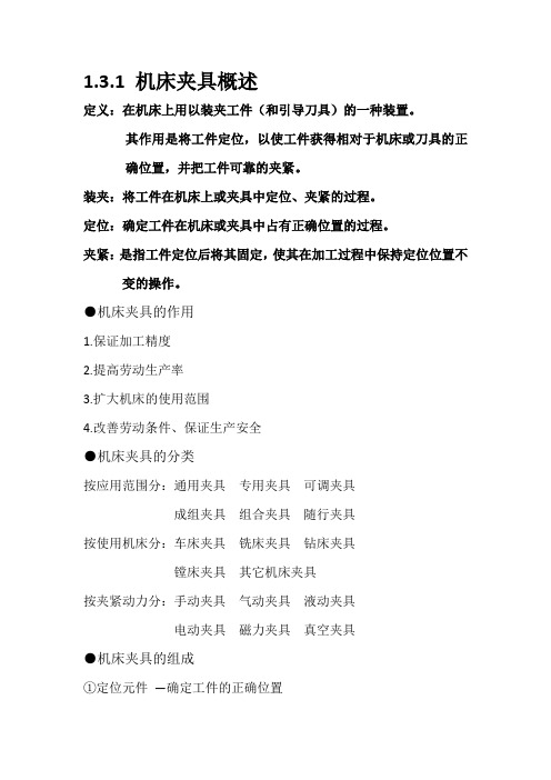
1.3.1 机床夹具概述定义:在机床上用以装夹工件(和引导刀具)的一种装置。
其作用是将工件定位,以使工件获得相对于机床或刀具的正确位置,并把工件可靠的夹紧。
装夹:将工件在机床上或夹具中定位、夹紧的过程。
定位:确定工件在机床或夹具中占有正确位置的过程。
夹紧:是指工件定位后将其固定,使其在加工过程中保持定位位置不变的操作。
●机床夹具的作用1.保证加工精度2.提高劳动生产率3.扩大机床的使用范围4.改善劳动条件、保证生产安全●机床夹具的分类按应用范围分:通用夹具专用夹具可调夹具成组夹具组合夹具随行夹具按使用机床分:车床夹具铣床夹具钻床夹具镗床夹具其它机床夹具按夹紧动力分:手动夹具气动夹具液动夹具电动夹具磁力夹具真空夹具●机床夹具的组成①定位元件—确定工件的正确位置②夹紧装置—夹牢工件,保证工件正确位置不变③对刀及导向装置—迅速确定刀具与工件的相对位置④夹具体—夹具的基础件⑤其他装置或元件—分度装置、联接元件等基准及其分类基准:用来确定生产对象上几何要素间的几何关系所依据的那些点、线、面。
根据功用:设计基准——设计图样中所采用的基准工艺基准——加工、测量、装配过程中使用的基准定位基准——为加工中用作定位的基准。
测量基准——测量时所采用的基准。
装配基准—— 是装配时确定零件或部件在产品中的相对位置所采用的基准。
1.3.2 工件的定位1、工件定位的方式1)直接找正定位—精度取决于工人技术水平单件小批生产,位置要求高。
2)划线找正定位—精度低单件小批,复杂件,毛坯精度低。
3)夹具定位—生产率高,定位精度高成批及大量生产。
●定位—加工前,工件在机床或夹具上占据一正确位置●夹紧—使工件在加工中不受力的作用发生位移、振动●装夹= 定位+夹紧(1)六点定则—用空间合理布置的六个支承点限制工件的六个自由度。
主要定位面∨3—三角形分布,支承范围大选大的面定位。
导向定位面∨2—两点连线不垂直主定位面,距离远选窄长的面定位。
专用夹具说明书

机械制造装备设计课程设计说明书题目后轮专用夹具设计系机械与运载学院专业机械设计制造及其自动化班级姓名顾育铭学号34指导教师赵元完成日期 2011 年 7 月 13 日沈阳理工大学应用技术学院沈阳理工大学应用技术学院机械制造装备课程设计说明书《机械制造装备设计》课程设计计划书一、课程设计目的1、本课程设计是《机械制造装备设计》课程的延续,通过设计实践,进一步掌握机械制造装备设计的一般方法。
2、培养学生综合运用机械制图、机械设计基础、金属材料及热处理、机械制造结构工艺等相关知识,培养工程设计的能力。
3、培养学生使用手册、图册、有关资料及设计标准规范的能力。
4、提高学生技术总结及编制技术文件的能力。
5、为毕业设计打下良好的基础。
二、课程设计题目后轮专用夹具设计三、课程设计的内容与基本要求(一)内容1、完成后轮工件的镗孔专用夹具总装配图。
2、完成镗孔专用夹具部分零件工作图。
3、编写设计计算说明书。
4、总工作量要求:总图量为:0#图纸1张;设计计算说明书15页。
(二)基本要求1、课程设计必须独立的进行,每人必须完成总工作量要求。
2、根据设计题目,完成规定的设计内容和工作量要求。
3、正确的运用手册、标准,设计图样必须符合国家标准规定。
4、设计计算说明书力求用工程术语,简明扼要,计算合理、准确,表达清晰,文字通顺简练,字迹工整。
四、进度安排1、1-2天分析零件草图,初定零件工作图,拟定夹具设计方案。
2、3-5天完成夹具装配草图设计。
3、6-10画零件工作图、夹具装配图、夹具零件图及设计计算说明书。
课程设计指导教师:赵元 2011 年 7 月 4 日1教研室主任:赵艳红2011 年 7 月 4 日摘要机械制造过程中用来固定加工对象,使之占有正确的位置,以接受施工或检测的装置。
又称卡具。
从广义上说,在工艺过程中的任何工序,用来迅速、方便、安全地安装工件的装置,都可称为夹具。
例如焊接夹具、检验夹具、装配夹具、机床夹具等。
- 1、下载文档前请自行甄别文档内容的完整性,平台不提供额外的编辑、内容补充、找答案等附加服务。
- 2、"仅部分预览"的文档,不可在线预览部分如存在完整性等问题,可反馈申请退款(可完整预览的文档不适用该条件!)。
- 3、如文档侵犯您的权益,请联系客服反馈,我们会尽快为您处理(人工客服工作时间:9:00-18:30)。
一、夹具设计任务
为加工下图零件中的三个Φ8的孔设计一个钻床专用夹具。
二、分析零件图及加工工艺工程的分析
(1)零件分析
该零件需要切削加工的地方有5个处:平面加工包括扇形板上端面、下端面;孔系加工包括φ20+00.01;小孔φ8和扇形板两个外圆弧面的加工。
不去除材料加工上下两个表面。
⑴以平面为主有:
①扇形板上端面的粗、精铣加工,其粗糙度要求是Ra=6.3;下端面的粗、精铣加工,其粗糙度要求是Ra=3.2;
②扇形板R54弧面采用数控机床加工,其粗糙度要求是Ra=3.2。
⑵孔系加工有:
①φ20+00.01孔的粗镗、半精镗,精镗加工,并且进行倒角1x45°。
其表面粗糙
度为Ra=3.2;
②φ8孔钻、铰加工,其表面粗糙度要求Ra=3.2;
扇形板毛坯的选择用铸造,因为生产率较高,所以可以免去每次造型。
单边余量一般在3.5-4mm,结构细密,能承受较大的压力,占用生产的面积较小。
(2)零件的工艺过程
工序1:铸造毛坯
工序2:粗铣零件的上端面,以下端面为粗基准。
工序3:粗铣零件的下端面,以上端面为粗基准。
工序4:精铣零件的下端面,以上端面为精基准。
工序5:精铣零件的上端面,以下端面为精基准。
工序6:对φ20+00.01孔进行粗镗,以下端面为基准。
工序7:对φ20+00.01孔进行半精镗,以下端面为基准。
工序8:对φ20+00.01孔进行倒角1X45°,以上、下端面为基准。
工序9:对φ20+00.01孔进行精镗,以下端面为基准。
工序10:用数控机床加工R54外圆弧,以下端面和孔为基准。
工序11:中检。
工序12:对φ8孔空进行钻——铰----精铰。
以φ22+00.021孔和下端面为基准。
工序13:清洗表面。
工序14:剔除毛刺。
工序15:终检。
三、根据零件图及加工工艺过程确定定位夹紧方案
根据题目所给的条件,在加工3个Φ8的孔前,其他表面均已加工完毕。
本设计采用六点定位。
即一个大平面限制三个方向的自由度(限制沿x轴旋转,限制沿y轴移动,限制沿z轴旋转);
Φ4的挡销限制一个方向的自由度(限制沿y轴旋转);
Φ20的短销限制两个方向的自由度(限制沿x轴移动,限制沿z轴移动)。
这样摆块的六个自由度被全部限制,摆块处于唯一位置。
为简化夹紧装置,故采用拉杆与开口垫圈,当拉杆受到拉力时,拉杆对开口垫圈有一个拉力,同时开口垫圈对大头圆柱的另一端面有一个压力,从而将拉杆压紧。
四、布置定位元件
所采用的定位元件为:大平面,挡销,短销。
1.大平面限制了四个自由度,限制沿y轴的移动,限制沿x轴的旋转,限制沿z轴的旋转。
2.挡销限制了一个自由度,限制沿y轴的旋转。
3.短销限制了两个自由度,限制沿x轴的移动,限制沿z轴的移动。
五、布置引导元件
本题中要求加工3个Φ8的孔,为了方便更换,我选用了快换钻套,其优点就是可以方便快换,快换钻套通过压紧螺钉来压紧,保证其在工作过程中,不会因外力而发生转动。
与此同时我选取了衬套,衬套的孔与快换钻套间隙配合,衬套的外圆柱面与钻模板上的孔过盈配合,衬套与钻套组合可以钻多个规格不同的孔,而只需在钻模板上钻一个孔,大大的节省了时间,提高了效率,降低了成本。
六、布置夹紧元件
本夹具用于在钻床上加工孔。
工件以端面、一短销、一挡销为定位基准,在定位环上实现完全定位,采用手动螺旋压紧机构夹紧工件,该夹紧机构操作简单、夹紧可靠。
拧紧开口垫圈旁的螺母,可以使工件与分度机构贴紧,拧紧另一个螺母整个装配体就夹紧了,这样就可以开动机床进行第一个孔的加工,先钻孔然后换刀具进行铰孔,这样一个孔就加工好了,旋转螺母,使分度盘与夹具体之间有空隙,这样拔出定位销就可以旋转分度盘,旋转到下一个孔,松开对位销旋紧螺母,这样就可以进行加工第二个孔,用同样的方法加工第三个孔,加工完后,松开开口垫圈旁的螺母,开口垫圈取下,换上下一个工件,如此往复进行。
此次设计是对扇形板零件的加工工艺和夹具设计,其零件为铸造,具有体积小,零件复杂的特点,由于面比孔易加工,在制定工艺规程时,就先加工面,再以面为基准来加工其它,其中各工序夹具都采用专用夹具,特别的对于加工φ8孔工序中,选一面两销的定位方式,并以操作简单的手动夹紧方式夹紧,其机构设计简单,方便且能满足要求。
七、课程设计心得
通过这次课程设计,使我对零件制造过程、加工工艺和夹具设计都有了更进一步的认识,也加深了对大学3年中所学基础知识的理解。
课程设计是理论联系实际的最有效方法,是检验学生学习质量、老师教育成效最直接的方法。
在具体设计过程中,必须考虑到方方面面的问题,可能在理论上正确无误的设计,在实际中往往存在各种问题。
这样,在设计时就必须考虑所设计的机构是否合理,在实际运用中能否正常工作,而不仅仅考虑理论上的可行性,课程设计使我学会了从实际出发加工零件和设计夹具,“实践是检验真理的唯一标准”。
在本次设计中,考虑到零件的加工难易、材料、成本等问题,所选用的零、部件都是操作简单,通用性较强的标准件,从现时以最低的成本实现最先进的加工。
但也很有不足之处。
无论怎样,这次的课程设计使我获益良多,过程曲折可谓一语难尽。
在此期间我也失落过,也曾一度热情高涨。
从开始时满富激情到最后汗水背后的复杂心情,点点滴滴无不令我回味无长。
在这次夹具课程设计中,用到了很多专业方面的知识,这就要求我们要在先掌握的前提下过才能运用,学过的知识不扎实要回去再温习,没有学过的知识就需要现学现用,无形之中对我们的要求就提高了,所谓先付出再收获,两星期下来突然觉得自己学到了很多知识,看到自己设计、编辑出来的东西感到很欣慰。
再则,在这期间,通过与同学一起研究探讨,互相学习,更加理解孔子论语中“三人行,必有我师”“三个臭皮匠,顶个诸葛亮”,深感团队的力量远大于单个人,无论个人有多么强悍,在讨论的过程中加深了同学间的友谊,增进了彼此的了解。
这也让我铭记在以后学习、工作要互相帮助,单靠自己一个人是做不出什么很大成就的。
八、参考资料
[1] 杨叔子,机械加工工艺师手册[M],北京:机械工业出版社,2002。
[2] 吴拓,方琼珊,机械制造工艺与机床夹具课程设计指导书,北京:机械工业出版社,2005
[3] 孙本绪,熊万武,机械加工余量手册,北京:国防工业出版社,1999。