异步电机控制文献综述
异步电动机矢量控制调速系统毕业论文中英文资料对照外文翻译文献综述

异步电动机矢量控制调速系统毕业论文中英文资料对照外文翻译文献综述异步电动机矢量控制调速系统中英文资料对照外文翻译文献综述The Design of the Vector Control System of Asynchronous Motor Abstract: Among various modes of the asynchronous motor speed control, vector control has the advantages of fast response, stability, transmission of high-performance and wide speed range. For the need of the asynchronous motor speed control, the design uses 89C196 as the controller, and introduces the designs of hardware and software in details. The Design is completed effectively, with good performance simple structure and good prospects of development.Keywords: Asynchronous motor, 89C196, Vector control1. IntroductionAC asynchronous motor is a higher order, multi-variable, non-linear, and strong coupling object, using the concept of parameters reconstruction and state reconstruction of modern control theory to achieve decoupling between the excitation component of the AC motor stator current and the torque component, and the control process of AC motor is equivalent to the control process of DC motor, the dynamic performance of AC speed regulation system obtaining notable improvement, thus makes DC speed replacing AC speed possible finally. The current governor of the higher production process has been more use of Frequency Control devices with vector-control.2. Vector ControlWith the criterion of producing consistent rotating magneto motive force, the stator AC current A i ,B i ,C i by3S/2S conversion in the three-phase coordinate system, can be equivalent toAC current s d i ,s q i , in two-phase static coordinate system, through vector rotation transformationof the re-orientation of the rotor magnetic field, Equivalent to a synchronous rotation coordinates ofthe DC current ed i ,e q i . When observers at core coordinates with the rotation together, AC machinebecomes DC machine. Of these, the AC induction motor rotor total flux r ψ, it has become the equivalent of the DC motor flux, windings e d equivalent to the excitation windings of DC motor , e d i equivalent to the excitation current, windings e q equivalent to false static windings, e q i equivalent to the armature current proportional to torque. After the transformation above, AC asynchronous motor has been equivalent to DC motor. As a result, imitating the control method of DC motor, obtaining the control variable of DC motor, through the corresponding coordinates anti-transformation, can control the asynchronous motor. As a result of coordinate transformation of the current (on behalf of magnetic momentum) space vector, thus, this control system achieved through coordinate transformation called the vector control system, referred to VC system.According to this idea, could constitute the vector control system that can control r ψ and e q idirectly, as shown in Figure 1. In the figure a given and feedback signal through the controllersimilar to the controller that DC speed control system has used, producing given signal *e qs i of theexcitation current and given signal *e ds i of the armature current, after the anti-rotation transformVR -1 obtaining *e qs i and *e ds i , obtains *A i ,*B i ,*C i by 3S/2S conversion. Adding the three signals controlled by current and frequency signal 1ω obtained by controller to the inverter controlled by current, can output three-phase frequency conversion current that asynchronous motor needs for speed.3. The Content and Thought of the DesignThis system uses 80C196 as controller, consists of detection unit of stator three-phase current unit of keyboard input, LCD display modules, given unit of simulation speed detection unit of stator three-phase voltage, feedback unit of speed and output unit of control signals. System block diagram shown in Figure 2, the system applies 16 bits MCU 80C196 as control core, with some hardware analog circuits composing the vector control system of asynchronous motor. On the one hand, 80C196 through the A/D module of 80C196, speed gun and the given speed feedback signals has been obtained, obtaining given torque of saturated limiting through speed regulator, to obtain the given torque current; Use a given function generator to obtain given rotor flux, through observation obtaining real flux, through flux regulation obtaining given excitation current of givenstator current, then the excitation current and the torque current synthesis through the K/P transformation, obtaining amplitude and phase stator current, after amplitude of stator current compared to the testing current , control the size of stator current through current regulator.; on the other hand, the stator current frequency is calculated by the simultaneous conversion rate for the time constant of the control inverter, regularly with timer, through P1,submitting trigger word to complete the trigger of the inverter.4. The Design of Hardware and SoftwareThe hardware circuits of the system mainly consists of AC-DC-AC current inverter circuit, SCR trigger inverter circuit, rectifier SCR trigger circuit, the speed given with the gun feedback circuit, current central regulation circuit, protection circuit and other typical circuits. The design of software includes: speed regulator control and flux detection and regulation.4.1 AC-DC-AC Current Converter CircuitThe main circuit uses AC-DC-AC Current Converter in the system as shown in Figure 3, and main features can be known as follows:1) Main circuit with simple structure and fewer components. For the four-quadrant operation, when the brake of power happens, the current direction of the main circuit keeps the same, just changing the polarity of the voltage, rectifier working in the state of inverter, inverter working in the state of rectifier. The inverter can be easily entered, regenerative braking, fast dynamic response. The voltage inverter has to connect to a group of inverters in order to regenerative braking, bringing the electric energy back to power grids.2) Since the middle using a reactor, current limit, is constant current source. Coupled with current Loop conditioning, current limit, so it can tolerate instantaneous load short-circuit, automatic protection, thereby enhancing the protection of over current and operational reliability3) The current inverter can converter with force and the output current instantaneous value is controlled by current inverter, meeting the vector control requirements of AC motors. Converter capacitor charging and discharging currents from the DC circuit filter by the suppression reactor, unlike a greater inrush current in voltage inverter, the capacitor’s utilization is of high level.4) Current inverter and the load motor form a whole, and the energy storage of the motor windings is also involved in the converter, and less dependent on the voltage inverter, so it has a certain loadcapacity.4.2 Inverter SCR trigger drive circuitThe Inverter SCR trigger drive circuit as shown in Figure 4. Inverter trigger signal is controlled by P1 of 80C196, slip signal outputting through P1 via PWM regulation in the SCM through the photoelectric isolation to enlarge, to control the trigger of the inverter. The system uses P1.6 as control and uses P1.0~P1.5 to control six SCR inverters separately, so the trigger circuits is composed by six circuits above.The principles of drive circuit of SCR trigger inverter are as follows: when the PWM from P1 is high signal after and gate, photoelectric isolation is not on, composite pipe in a state of on-saturated, the left side of the transformer forming circuit, and that the power of the signal amplifies (current enlarges); when the PWM from P1 is low signal after and gate, photoelectric isolation is on, composite pipe in a state of cut-off, and the left side of the transformer can not form circuit; thus, composite pipe equivalent to a switch, and its frequency relied on the frequency of the PWM, so the left side of the transformer form AC signals, to trigger SCR inverter after transformer decompression, half-wave rectifier and filter.4.3 Current Loop conditioning circuitsAfter the vector calculation, outputting given current through D/A module, testing feedback current by the current testing circuit, sending them to the simulator of the P1 regulator to regulate, can eliminate static difference and improve the speed of regulation. The output of the analog devices can be regarded as the phase-shifting control signals of the rectifier trigger. Current Loop conditioning circuits as shown in figure 5.4.4 The control of speed regulatorSpeed regulator uses dual-mode control. Setting a value T N of speed error, when the system is more than the deviation (more than 10 percent of the rated frequency), as rough location of the start, using on-off control, at this time, speed regulator is in the state of amplitude limit, equivalent to speed loop being open-loop, so the current loop is in the state of the most constant current regulation. Thus, it can play the overload ability of motor fully and make the process of regulation fastest possibly. When the system enters into a state of small deviation, the system uses PI linear control instead of on-off control. As result, absorbing the benefits of non-linear and linear, the system meets stability and accuracy. The speed regulator flowchart is as shown in figure 6.4.5 Flux RegulationSlip frequency vector control system can be affected by the motor parameters, so that the actual flux and the given flux appear a deviation. This system is of observation and feedback in the amplitude of the magnetic flux, regulating flux of the rotor, actual flux with the changes of given flux.Flux regulator is also the same as the speed regulator, using PI regulator. The discrete formula is:n i S i m m m t n e T n e k n i n i /)}()({)1()(+∆+-= (1)Plus a reminder to forecast for correction:)1()(2--=n i n i I m m m (2) In the formula, m k is proportional coefficient, n t is integral coefficient, s T is sampling period, m I is the actual output value.)1()(--=∆n e n e e n (3))()(2*2n n e n Φ-Φ= (4)When it is in the state of low frequency (f<5HZ), 1r can not be ignored, the phase difference between 1V and 1E enlarges, and the formula 1V ≈'1V no longer sets up. Through the Approximate rotor flux observer and the formula 1101112/)(L I r I V L I m T m m --==Φω to observe the flux amplitude, only open-loop control of flux, that is, to calculate from a given flux, and that is m m L I /*2Φ=.In addition, in order to avoid disorders, or too weak and too strong magnetic, limiting the output m i in preparation for the software, making it in the ranges from 75% to 115% rated value.5. Design SummaryThis text researches the vector control variable speed control system of the asynchronous motor design. The SCM 80C196 and the external hardware complete the asynchronous motor speed vector control system design efficiently, and meet the timing control requirements. The vector control system design thinks clearly, has a good speed performance and simple structure. It has a wide range of use and a good prospect of development from the analysis and design of the speed asynchronous motor vector control systems.The innovations:(1) Complete the data acquisition of the speed and voltage, output the control signal and save the devices effectively with the help of the 80C196 microcontroller owned A/D, D/A.(2) Because the Current Source Inverter uses forced converter, the maximum operating frequency is free from the power grid frequency. And it is with wide speed range.(3) This system uses constant flux to keep the constant flux stably. Use stator physical voltage amplitude to approximate the observed flux amplitude value. The magnetic flux overcomes the impact of the parameters changes. This way is simple and effective.Figure 1. Vector Control System PrincipleFigure 2. Scheme of SystemFigure 3. AC-DC-AC Current inverter CircuitFigure 4. Inverter SCR trigger drive circuitFigure 5. Current Loop conditioning circuitsFigure 6. Flux regulation flowchartReferencesHisao Kubota and Kouki Matsuse. (1994). Speed Sensorless Field-Oriented Control of Induction Motor withRotor Resistance Adaptation. IEEE Trans. Ind. Appl., vo1.30, No.5,pp.1219-1224.Li, Da, Yang, Qingdong, and Liu, Quan.(2007). The DSP permanent magnet synchronous linear motor vector control system. Micro-computer information, 09-2:195-196Liu, Wei. (2007). The application design about vector control of current loop control. Micro-computer information, 07-1: 68-70Zhao, Tao, Jiang, WeiDong, Chen, Quan, and Ren, Tao. (2006). The research about the permanent magnet motor drive system bases on the dual-mode control. Power electronics technology, 40 (5) :32-34异步电动机矢量控制调速系统设计摘 要:异步电动机的各种调速方式中,矢量控制的调速方式响应快、稳定性好、传动性能高、调速范围宽。
异步电动机设计文献综述

本科毕业设计(论文)文献综述2013 年12 月18 日本科生毕业设计(论文)文献综述评价表75KW三相鼠笼异步电动机设计1前言:现在社会中,电能是使用最广泛的一种能源,在电能的生产、输送和使用等方面,作为动力设备的电机是不可缺少的一部分。
电机是各个行业生产过程及日常生活中普遍使用的基础设备,它是进行电能量和机械能量转换的主要器件。
它在现代工业、现代农业、现代国防、交通运输、科学技术、信息传输和日常生活工工艺是提高电机可靠性和经济指标的根本途径。
国外公司注重新产品开发,在电机的安全、噪声、电磁兼容等方面很重视。
国外的先进水平主要体现在电机的可靠性高,寿命长,通用化程度高,电机效率不断提高,噪声低,重量轻,电机外形美观,绝缘等级采用F级和H级。
国内市场供大于求,只能去发展特殊、专用电机,开发新产品,满足配套主机行业的特殊需要;国外市场由于普通中小型电机特别是小型电机是传统工业产品,耗用原材料及工时多而获利少,是劳动密集型产品,工业发达国家普遍不愿意生产,纷纷转向发展中国家加工或购买。
中国是发展中国家中最大的国家,物质资源及人力资源很丰富,有广阔的市场,进入21世纪可望在中小型电机的出口数量、产品档次、创汇额上有重大突破。
有待国内中小型电机行业中的企业去争取,去竞争。
随着科学技术的发展和人类环保意识的加强,人们越来越重视环境的噪声污染问题。
因此,电机的噪声成为考核产品竞争力的一个重要因素。
为提高电动机的品质,必须采取措施削弱电磁噪声。
随着社会生活质量的不断提高,绿色电机的概念已经提出并被人们所接受。
虽然这个概念目前还是抽象的,但从环保角度看,地震动,低噪声,无电磁干扰,子导体中产生感应电流,转子在感应电流和气隙旋转磁场的相互作用下,又产生电磁转柜(即异步转柜),使电动机旋转。
异步电动机的工作原理用箭头式子可以简单的表示如下:定子绕组通入三相交流电流→产生旋转磁场→切割转子绕组→转子绕组产生感应电动势→转子中产生感应电流→转子电流与磁场作用→产生电磁转矩→运行。
电机文献综述
电机文献综述(08级)学生姓名金其超学号 ******** 院系工学院机电系专业自动化 082填写日期2010-09-27电机行业综述前言电机行业是一个传统的行业。
经过200多年的发展,它已经成为现代生产、生活中不可或缺的核心、基础,是国民经济中重要的一环。
作为劳动密集型产业,我国发展电机制造业有着得天独厚的优势。
到目前为止,我国的电机制造业已经具有一定规模。
据全国电工行业统计,2006年全国交流电机产量达到15000万kw,同比增16%;汽轮发电机9583万kw,同比增长21.64%,水轮发电机组1922万kw,同比增长49.57%。
在经过了2006年下半年的低速发展之后,2007年到现在,我国电机制造行业保持高速发展态势。
电机出口市场的需求还将在相当一个时期趋于稳定,交流电动机的国际市场需求也十分可观,并将持续处于高速增长阶段。
随着电机产品国外市场的进一步拓宽,中小型电机在出口数量、品种、产品档次、创汇额上将会有重大突破。
未来出口电机产量增长主要外部原因在于世界经济稳定增长,促进了行业贸易产量的增长。
内因是国内出口退税率改革导致企业加快出口步伐,及国内外资企业规模的不断扩大和数量的快速增加,产品竞争提高,在国内形成巨大的效益,也刺激了出口上升。
随着生产现代化程度的不断提高和人们对家用电器、汽车等消费的不断增加,市场对电机的需求也将越来越大。
预计到2010年,全国发电装机容量将达到6.6亿千瓦左右,平均每年将投产发电装机容量3700万千瓦以上,年均增长7.8%左右。
而电动机的需求与发电设备的需求呈1∶3.51的正比关系,据此分析,大型、中小型交流电动机产品在国内市场的有效需求会保持稳定增长。
正文电机的起源和发展电机工作基本原理是利用带电导体和磁场间的相互作用而把电能变为机械能。
电动机结构主要包括两部分:转子和定子。
转子为电动机的旋转部分,由转轴座组成,导体绕组的排列方式决定电动机的类型及其特性。
交流异步电机控制方法综述
传 统 的变 频 调 速 系 统 的控 制 量 是 交 流 电 动 机 的 定 子 电压 幅 值 和 交 流传 动控 统 。 特 点 是 在静 止 的 两 相 坐标 系 中控 制 定 子 磁 链 幅 值 基 其 频 率 , 能按 电 动 机 稳 态 运 行 规 律 进 行 控 制 . 能 任 意 控 制 定 子 磁 通 本保 持 恒 定 并 实现 转 矩 反 馈 控 制 。 核 心 问题 是 转 矩 和定 子 磁 链 反 馈 只 不 其 和转 子 磁 通 矢 量 大 小 和 位 置 . 以输 出 的 电磁 转 矩 只 能 按 稳 态 规 律 变 模 型 。 所 以及 如何 根 据 转 矩 和 磁 链 控 制 信 号 来 选 择 电 压 空 问 矢 量 控 制 器 化 , 态性能差 , 动 系统 的 响应 慢 。 采用 矢 量 或 者 直 接 转 矩 控 制 技 术 的 异 的开 关 状 态 。直 接 转 矩 控 制 磁 场 定 向所 采 用 的是 定 子 磁 链 , 只要 知 道 步 电 动 机 可 以像 直流 电 动机 一 样 进 行 控 制 . 而 大 幅 度 提 高 交 流 电 机 定 子 电阻 就 可 以把 它 观 测 出 来 , 此 直 接 转 矩 控 制 大 大减 少 了矢 量 控 从 因 的动 态 性 能 和使 用范 围 。通 过 对 异 步 电动 机 数 学 方 程进 行 解 耦 . 而 制 技 术 中控 制 性 能 易 受 参 数 变 化 影 响 的 问题 ; 且 直 接 转 矩 控 制 直 接 从 而 对 异 步 电 动 机 的励 磁 电 流和 转 矩 电流 分 别 进 行 控 制 , 空 间 磁 场 中 根 在 定 子 坐 标 系 下 分 析 交 流 电 机 的 数 学 模 型 .控 制 电机 的 磁链 和 转矩 . 在 据 控 制 的动 态 要 求 , 算 出满 足 要 求 的 电 流 或 电 压 矢 量 . 动 机 的 电 不 需 要 为 解 祸 而 简 化 交 流 电 机 数 学 模 型 , 省 掉 矢 量 旋 转 变 化 等 复 杂 计 电 即 磁 转 矩 可 以 瞬 时 变 化 , 受 控 制 规 律 的 影 响 , 样 就 大 大 方 便 高精 度 的变 换 和 计 算 。但 是 其 缺 点 是 : 出转 矩 有 脉 动 , 速性 能 较 差 , 制 不 这 输 低 限 的 控 制技 术 现 实 。本 文 介 绍 几 种 常 用 的 异 步 电 动 机 控制 方 法 。
异步电机变频调速系统数字检测装置设计【文献综述】

文献综述信息与计算科学异步电机变频调速系统数字检测装置设计一、前言在电力工业发展初期曾用电解化学原理进行参数测量,1890年,发明了感应式电磁原理电能表,沿用至今。
[4]传统的电参数测量方法,一般通过对模拟电压信号的采样和计算来完成测量。
主要经历了以下几个阶段:第一阶段,以模拟测量为主,通过基于电磁通量原理的指针式一起,如指针式电压表,电流表,功率表等,在线测量出电网的各种电力参数。
但其机械结构和电磁通量结构一般比较复杂,测量的精度也很难提高。
第二阶段,以直流采样为主,将被测量整流成直流量,通过测量平均值来测量电参数的有效值。
此方法软件设计简单,计算速度快,对采样值只需作比例变换即可得到被测量的数值。
但是,直流采样方法存在一些问题,如测量准确度直接受整流电路的准确度和稳定性的影响,整流电路参数调整困难等。
第二阶段,以交流采样为主,先将电压、电流信号经高精度的电压、电流互感器变成数字系统可测量的交流小信号,然后再送入微处理器进行计算。
交流采样是对被测信号的瞬时值进行采样,然后对采样值进行分析计算获取被测量信号的,对采样的速率要求高,程序计算量相对较大,但它的采样值中所含信息量大,可通过不同的算法获取所关心的多种信息(如有效值、相位、谐波分量等),实时性好,精度高。
[3][4][5]二、各电参量检测方法和器件电流检测有多种方法,最通用的方法是采用阻性分流器、互感器或霍尔传感器。
阻性分流器工作时与负载串联,无法进行隔离测量。
互感器只适用于50 Hz 工频交流的测量。
霍尔检测技术综合了互感器和分流器技术的所有优点,同时又克服了互感器和分流器的不足,采用一只霍尔电流电压传感器/变送器模块检测元件,既可以检测交流,也可以检测直流,甚至可以检测瞬态峰值,同时又能实现主电路回路和电子控制电路的隔离,因而是替代互感器和分流器的新一代产品。
[7]目前,电压检测也多数采用霍尔传感器。
光电式旋转编码器是检测转速或转角的元件,旋转编码器与电动机相连,当电动机转动时,带动编码器旋转,产生转速或转角信号。
毕业论文:异步电机直接转矩控制研究
毕业论文:异步电机直接转矩控制研究摘要20世纪60年代以后,由于生产发展需要,交流调速的到发展。
20世纪70年代后,科学技术的发展使得交流调速有了质的发展飞跃,主要有以下四个阶段:(1) 电力电子器件的发展促进了交流调速的发展。
电力电子器件主要用于电动机的变频调速系统。
(3)矢量变换控制的发展奠定了现代交流调速高性能的基础。
此类调速采用参数重构和状态重构的现代控制的理论实现交流电机定子电流励磁分量和转矩分量的耦合,实现了等效于直流调速的控制过程,使得交流调速性能得到改善和提高。
继矢量控制后直接转矩控制技术的运用,可获得更大的瞬时转矩和极快的动态响应。
(4) 微型计算机技术与大规模集成电路的发展为现代调速系统的发展提供了重要技术手段。
由于微机控制技术,尤其是以单片机与dsp为控制核心的微机控制技术,促使交流调速系统走向数字化控制,对信息的处理量的增大,可以实现许多复杂的控制方式。
提高了交流调速系统的可靠性和操作设置的多样性和灵活性,降低交流调速装置的成本和体积。
1.2 直接转矩控制技术的现状与发展趋势1.2.1 直接转矩控制技术的现状1985年,德国人m.depenbrock提出了直接转矩控制理论,在实现磁链的同时也实现了对直接转矩的控制。
直接转矩控制技术一诞生,就以自己新颖的控制思想,简洁明了的系统结构,优良的静态性能受到了普遍的注意和得到了迅速的发展。
根据m.depenbrock所提出的直接转矩控制理论所实现的系统中,其磁链的轨迹是按正六边形运动,其六边分别有相应的六个非零电压矢量与之对应,可简单的切换六个工作状态直接由六个非零电压矢量完成六边形磁链轨迹,磁环控制简单。
日本东芝公司的takahashi教授于1986 年提出了磁链轨迹的园形方案,即让磁链矢量基本上沿园形轨迹运动。
这是一种磁链的实时控制,通过比较实时计算所得的实际磁链幅值与给定值相比较,并同时考虑此时磁链所处的位置来选择电压矢量及持续时间的长短。
交流异步电机控制方法综述
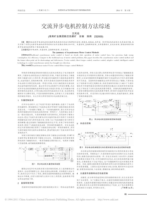
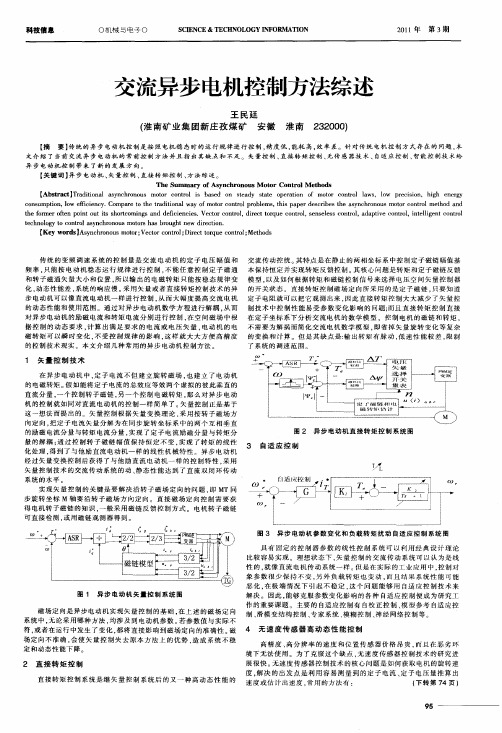
图 1 异步电动机矢量控制系统图
磁场定向是异步电动机实现矢量控制的基础,在上述的磁场定向 系统中,无论采用哪种方法,均涉及到电动机参数。 若参数值与实际不 符,或者在运行中发生了变化,都将直接影响到磁场定向的准确性。 磁 场定向不准确,会使矢量控制失去原本方法上的优势,造成系统不稳 定和动态性能下降。
(下转第 74 页)
95
●
● ●
2011 年 第 3 期
SCIENCE & TECHNOLOGY INFORMATION
○I T 论坛○
科技信息
当发送“探路”数据包的数目不同时,网络资源的利用率也不同, 如图 5。 当 N 较小时,如图 6 中 N 为 1-3 时,随着 N 的增大,资源利用 率会明显的增加, 但随着 N 发送数目的增多, 会过多的消耗链路资 源,造成链路资源利用率严重降低,如图 6 中 N 为 4-12。
4 无速度传感器高动态性能控制
高精度、高分辨率的速度和位置传感器价格昂贵,而且在恶劣环
境下无法使用。 为了克服这个缺点,无速度传感器控制技术的研究进
展很快。 无速度传感器控制技术的核心问题是如何获取电机的旋转速
度,解决的出发点是利用容易测量到的定子电流、定子电压量推算出
速度或估计出速度,常用的方法有:
科技信息
○机械与电子○
SCIENCE & TECHNOLOGY INFORMATION
2011 年 第 3 期
交流异步电机控制方法综述
王民廷 (淮南矿业集团新庄孜煤矿 安徽 淮南 232000)
【摘 要】传统的异步电动机控制是按照电机稳态时的运行规律进行控制,精度低,能耗高,效率差。 针对传统电机控制方式存在的问题,本 文介绍了当前交流异步电动机的常前控制方法并且指出其缺点和不足。 矢量控制、直接转矩控制、无传感器技术、自适应控制、智能控制技术给 异步电动机控制带来了新的发展方向。
交流异步电机控制技术发展综述
交流异步电机控制技术发展综述
近几十年来,异步电机的应用在不断扩大,其中最重要的是它的控制
技术的发展。
为了确保异步电机的有效控制,研究者们采用了各种不同的
控制方法。
因此,本文综述了近几十年来异步电机控制技术的发展情况。
首先,介绍了异步电机的基本结构和原理,包括电子电路的组成、控
制方式的基本原理。
然后,针对异步电机控制的关键问题,在控制方面,
介绍了传统的速度控制方法、模糊控制方法、神经网络控制方法、模型预
测控制方法和综合新技术控制方法,分别介绍这些方法的基本原理和特点,以及每种方法适用的场合。
随着电子技术和计算机技术的发展,控制理论和技术也在不断改进和
改善。
例如,基于现代数字控制理论,引入了多变量PID算法,改善了电
机控制的精度和抗侧摆特性;引入了各种模型预测控制算法,改善了系统
的稳定性和鲁棒性;发展了基于时变自抗扰技术的控制算法,改善了电机
控制的准确性。
最近,人们开始引入传感技术来检测和控制异步电机。
- 1、下载文档前请自行甄别文档内容的完整性,平台不提供额外的编辑、内容补充、找答案等附加服务。
- 2、"仅部分预览"的文档,不可在线预览部分如存在完整性等问题,可反馈申请退款(可完整预览的文档不适用该条件!)。
- 3、如文档侵犯您的权益,请联系客服反馈,我们会尽快为您处理(人工客服工作时间:9:00-18:30)。
文献综述毕业设计题目:基于freescaleDSC的电机控制设计基于freescaleDSC的电机控制设计滕昭跃(08电子信息科学与技术(1)班E08640119)一、前言电机行业是一个传统的行业。
经过多年的发展,它已经成为现代生产、生活中不可或缺的核心、基础,是国民经济中重要的一环。
电动机主要分同步电动机、异步电动机与直流电动机三种,分别应用于不同的场合,而其中又以三相异步电动机的使用最为广泛。
到目前为止,我国的电机制造业已经具有一定规模。
在现代电动机控制中,长期以来存在着交流调速和直流调速方案之争,早在19世纪末,电力系统中就有过交流供电和直流供电之争,结果经过半个世纪的争论,由于三相交流电的发明,使电力系统的交流化取得了胜利[1]。
由于电力电子器件的不断发展,这对交流电机的控制和调速奠定了物质基础。
电力电子器件是实现弱电控制强电的关键所在。
以普通晶闸管构成的方波形逆变器被全控型高频率开关器件组成的脉宽调制(PWM)逆变器取代,正弦波脉宽调制(SPWM)逆变器及其专用芯片得到了普遍应用。
在现代电机控制理论中,交流变压变频技术是一种转差功率不变高效型调速技术,它是现代交流调速的主要控制方法,自20世纪60年代获得突破性进展以来,一直受到人们的高度重视。
交流变压变频技术按其控制方式可简单分为:V/F恒定正弦脉宽调制(SPWM)、电压空间矢量(SVPWM)、矢量控制和直接转矩控制三代控制方式[2]。
在20世纪80年代初期出现了数字信号处理器,DSP(Digital Signal Processors)以运算速度快为显著特征而单片机则以数字控制功能强为特点。
电动机的数字控制既要求控制器有强大的 I/O 控制功能,又要求控制器有高速的信号处理能力以实现实时控制。
因此世界上各大DSP生产商将DSP的高速运算速度与单片机的高控制能力相结合,开发出电机控制的专用DSC。
其中由飞思卡尔公司生产的56f8300系列DSC就是为电机控制所研发。
这种 DSC是目前用于电机控制中功能最强大的控制器。
它足以满足以上几种控制方式的需求[3] [4]。
二、电机的交流调速从世界上第一台电动机诞生以来,交流电机变频调速技术的发展一直没有得到大规模的应用。
这主要是由于交流电动机本身的控制复杂性以及电力电子技术不成熟,控制方法不完善造成的。
但是,从20世纪70年代以后,随着电力电子技术和微电子技术的发展,带动了交流调速系统的兴起和发展,逐渐打破了直流调速系统占据的统治地位。
针对交流电机(尤其是笼型感应电机)动态数学模型的非线性多变量强祸合特点,并随着智能控制技术的发展,许多学者提出了各种控制策略和技术方法。
包括无速度传感器矢量控制技术、直接转矩控制技术、基于神经网络控制的矢量控制技术、空间电压矢量控制技术等[8]。
现代交流调速技术的发展依赖于微电子学、电力电子技术、计算机控制、现代控制理论和逆变技术的发展以及交流电动机制造技术的发展,是一门多学科交叉技术。
近年来,交流电机的驱动在工业中得到了非常广泛的应用。
2.1直流电机与异步电机调速性能比较异步电机相对于直流电机,具有坚固耐用,价格便宜,易于维护等显著特点,在各行各业得到广泛应用。
但是,异步电机的调速性能远比直流电机差,这限制了异步电机在调速场合的应用。
由电机原理可知,电机调速的本质是控制电机的电磁转矩实现加减速,达到调节转速的目的。
电动机的电磁转矩是由主磁场和电枢磁场的相互作用产生的。
主磁场和电枢磁场产生方法的不同,以及两者之间相互作用形式的不同产生了电机不同的调速性能。
直流电机调速性能优异、可控性好是因为它具备以下几个条件:(1)主磁场由直流励磁电流产生,用补偿绕组克服电枢反应,一般可认为主磁场是稳定的直流磁场;(2)当电刷位于几何中性线时,电枢磁场和主磁场在空间上是垂直的,不产生耦合;(3)励磁电流和电枢电流互相独立,由各自所在回路控制,易于实现;(4)在工程实现中,直流电机可以视为单输入/单输出的二阶线性系统(SISO ),输入为电枢电压,输出为转速。
若忽略电枢反应和磁场饱和,直流电机的输出转矩可以表示为f a af e I I G T = (1)式中,e T 为电磁转矩,af G 为直流电动机的电动势常数,a I 为电枢电流,f I 为励磁电流。
直流电机的构造决定了励磁电流f I 产生的磁链f ψ与电枢电流a I 产生的磁链a ψ是垂直的,即两个矢量之间是解耦的。
通过改变a I 控制转矩时,磁链f ψ不受影响,且在f ψ为额定值时,可以获得快速的瞬态响应和较高的单位安培转矩;通过f I 改变控制磁链f ψ时,不会影响到a ψ。
这就是调速所希望的独立性、解耦性。
应用经典的线性系统控制理论以及相应的工程设计方法可以很方便地分析和设计直流电机的调速系统。
异步电机和直流电机相比,具有以下特点:(1)三相异步电动机的定子上施加三相对称正弦交流电流,产生一个空间旋转磁场;(2)转子电流产生的旋转磁场在稳态时与定子电流产生的旋转磁场同步旋转,但相位不同,在空间上不存在垂直关系,也就不存在解耦特性;(3)异步电机多为鼠笼型,转子短路,只能调节定子电流;(4)异步电机的动态数学模型是至少七阶的多输入多输出系统(MIMO )。
显然,异步电机的动态数学模型极复杂,只有通过有效的简化与控制技术实现解耦才有可能获得像直流电机类似的调速性能[5]。
2.2异步电机的控制由于异步电机的控制与直流电机的控制不同,没有专门的励磁绕组或者永磁体,因此,异步电机的磁场控制现得尤其困难。
因此,人们提供了多种异步电机控制策略,其核心均为对异步电机磁场的有效控制,其控制方法有开环控制,闭环控制,直接控制和间接控制等多种形式。
2.2.1变压变频控制(VVVF )[1]异步电机的同步转速是由给电机供电的电源频率和电机的极对数决定的,当供电频率改变时,电机的同步转速也随之改变。
在负载条件下,电机转子的实际转速低于电机定子的同步转速,其转差的大小与电机的负载有关。
异步电机的稳态 T 形等效电路如图 1所示。
根据电机学基本原理,电机定子每相电动势的有效值为:m N s g s k N f E Φ=144.4 ( 2 )式中:g E 为气隙磁通在定子每相中感应电动势的有效值,单位为V ;1f 为定子频率, 单位为Hz ; s N 为定子每相绕组串联匝数;s N k 为基波绕组系数;m Φ每极气隙磁通量,单位为Wb 。
图 1异步电机稳态 T 形等效电路在电机控制过程中,使每极磁通;m Φ保持恒定值不变是关键一环,其幅值通常保持为额定值。
这是因为,如果磁通太弱,就没有充分利用电机的铁心,并影响电机的输出转矩;如果过分增大磁通,又会使铁心饱和从而导致过大的励磁电流,增加电机的铜耗和铁耗,使电机温升过高, 严重时会因绕组过热而损坏电机。
在异步电机中,磁通m Φ是由定子和转子磁动势合成产生的,因此由式( 1 )可以看出, 只要将气隙感应电动势g E 和定子电压频率1f 协调控制,就能够将磁通m Φ控制为恒定值。
其关系式为:1f E K gm ∙=Φ ( 3 )然而,绕组中的感应电动势的检测和控制是比较困难的,当定子频率较高时,感应电动势的值g E 也较大,因此可以忽略定子阻抗所产生的压降,得到定子端电压近似与感应电势相等,即g s E U ≈,因此式 ( 2 )可以改写为:1f U K sm ∙'≈Φ ( 4 )但是在低频时g E 和s U 都较小,定子阻抗压降所占的份量就比较显著,不能忽略。
这时需要人为地把电压s U 抬高一些,以便对定子阻抗压降作近似补偿。
其中带定子压降补偿的恒压频比控制特性如图2中的曲线II 所示,无补偿的控制特性如曲线I 所示。
这种变频调速方法又称变频变压调速( V ariable V oltage V ariable Frequency),简称 VVVF 控制。
图2恒压频比控制特性2.2.2正弦脉宽调制控制(SPWM )[6]交流电气传动中的脉宽调制技术一般称为正弦脉宽调制(SPWM )。
SPWM 波的基本实现方法是利用三角波对症先控制信号进行调制,通过调节脉冲宽度来形成包含正弦基波的脉冲调制波。
它具有输出波形好、谐波分量少和调速范围宽等特点。
SPWM 控制脉冲可以用模拟电子电路产生,但它存在使用元件多、控制线路复杂、控制精度难以保证等缺点。
经常采用微机与专用芯片混合控制SPWM 变频调速系统或单片机生成SPWM 控制脉冲的交流电动机变频调速系统,但从微机控制角度看,希望少用硬件,尽可能多地用软件来完成各种功能,以降低成本,提高装置的可靠性和灵活性。
对于交流异步电机,其转速()s p f n -=160 ( 5 )其中p :为电动机磁极对数f :为电源频率s :为转差率 由式( 5 )可知,影响电动机转速的因素有:电动机的磁极对数,转差率和电源频率。
其中,改变电源频率来实现交流异步电动机调速的方法效果最理想,这就是所谓的变频调速。
在电动机调速时,总是希望保持每极磁通为额定值不变,磁通太弱没有充分利用电动机的铁芯,是一种浪费。
若要增大磁通,则会使铁芯饱和,导致电动机过热而损坏。
由式( 1 )可知,在基频(额定频率)以下变频时,定子电压s U 也要随之变化,这样才能保持磁通恒定。
在基频以上调节时, f 增高,电压不能增加得比额定电压还要高,这样磁通将会与频率成反比降低,相当于直流电动机的弱磁升速。
如何才能实现变频的同时变压,这就需要用到正弦波脉宽调制(SPWM )。
原始的SPWM 是由模拟控制来完成的,现在已经很少应用,数字控制是 SPWM 目前常用的控制方法。
可以采用微机存储预先计算好的SPWM 数据表格,控制时根据指令调出;或者通过软件实时生成SPWM 波形;也可以采用大规模集成电路专用芯片产生 SPWM 信号。
对于数字SPWM 控,根据产生信号原理的不同,可以将SPWM 的采样方法分为等效面积算法、自然采样方法和规律采样方法。
(1) 等效面积算法正弦脉宽调制的基本原理就是按面积相等的原则构成与正弦波等效的一系列等幅不等宽的矩形脉冲波形。
根据已知数据和正弦数值可以依次算出每个脉冲的宽度,用于查表或实时控制。
这是一种最简单的算法。
(2) 自然采样法移植模拟控制的方法,计算正弦调制波与三角载波的交点,从而求出相应的脉宽和脉冲间歇时间,生成 SPWM 波形。
(3) 规则采样法自然采样法的主要问题是,SPWM 波形每一个脉冲的起始和终了时间对三角波的中心线不对称,因而求解困难。
工程上实用的方法要求算法简单,只要误差不太大,许作一些近似处理,这样就提出了规则采样法。
2.2.3空间矢量脉宽控制(SVPWM )[5]空间矢量的基本思想就是把异步电动机经过坐标变换等效成直流电动,然后仿照直流机的控制方法,求得直流电动机的控制,再经过相应的反变换,就可以控制交流电动机了。