西门子SIEMENSQRA4火焰探测器说明说下载
西门子 FDL241-9-C线型光束感烟火灾探测器 说明书
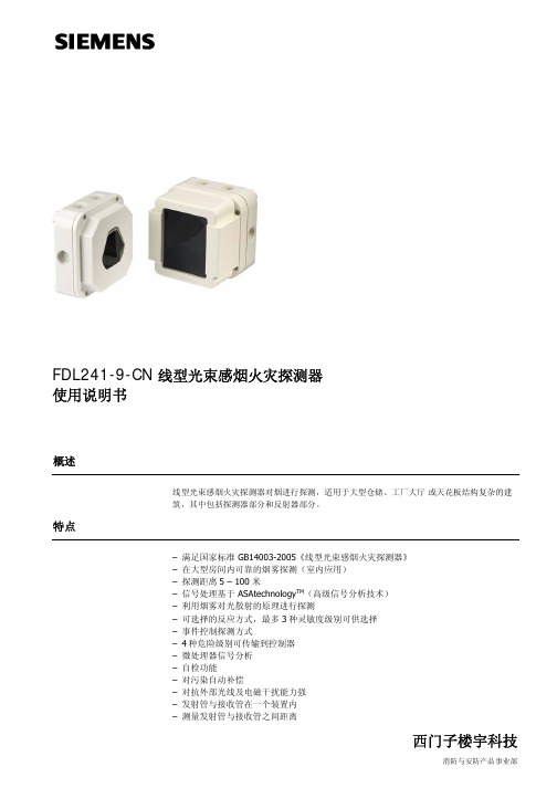
FDL241-9-CN 线型光束感烟火灾探测器使用说明书概述线型光束感烟火灾探测器对烟进行探测,适用于大型仓储、工厂大厅或天花板结构复杂的建筑,其中包括探测器部分和反射器部分。
特点– 满足国家标准 GB14003-2005《线型光束感烟火灾探测器》– 在大型房间内可靠的烟雾探测(室内应用)– 探测距离5 – 100 米– 信号处理基于 ASAtechnology TM(高级信号分析技术)– 利用烟雾对光散射的原理进行探测– 可选择的反应方式,最多3种灵敏度级别可供选择– 事件控制探测方式– 4种危险级别可传输到控制器– 微处理器信号分析– 自检功能– 对污染自动补偿– 对抗外部光线及电磁干扰能力强– 发射管与接收管在一个装置内– 测量发射管与接收管之间距离– 通过FDnet与控制器通讯(独立编址)功能– 探测器由发射管和接收管组成。
发射管发出一束红外光,光束通过对面的棱形反射器再返回到接收管。
接收管将收到的红外信号转换成电信号,供微处理器进行分析处理。
– 当有烟雾穿过探测区,红外信号会减弱。
当信号达到预定值时,探测器向控制器发送相应的危险等级。
– 距离测量用于识别外部事件。
– 内置报警灯显示报警状态。
应用– 大型仓储及生产车间– 房顶结构复杂,或有历史价值的天花板– 有遮挡的庭院– 中庭类型建筑– 接待大厅结构线型光束感烟火灾探测器由底座(1)、端子盘 (2)、探测单元 (3) 及盒盖 (4)四部分组成。
指示灯探测器有一个指示灯,用来指示探测器工作状态(见下表)。
注:指示灯闪烁模式取决于所使用的控制器。
探测器工作状态指示灯状态(可由控制器配置)正常灭测试每1秒闪一次报警常亮外形尺寸单位:mm安装图 1图 2(9)-+图 3图 4图5准备工作– 表面安装通常直接安装在靠近天花板的墙上。
– 必须确保探测器与反射器之间的光路顺畅。
– 探测器与反射器之间的距离必须是5-100米。
距离天花板或其它障碍物的间距不应小于30厘米。
西门子QRI型号Infrared Flame Detectors商品说明书

7719Infrared Flame Detectors QRI...Infrared flame detectors for use with Siemens burner controls, for the supervi-sion of gas, oil and other flames that emit infrared light.The QRI... are suited for burners of any capacity, either in continuous or intermit-tent operation.The QRI... and this Data Sheet are intended for use by OEMs which integrate theflame detectors in their products.Use, featuresKey features of the QRI... flame detectors:- Detector with infrared-sensitive flame detecting element- Integrated flame signal amplifier- Designed for frontal and lateral (90°) illumination- Suited for use with burner controls type LMV5...- Secured to the burner with flange and clampThe spectral sensitivity of the QRI... is a maximum of about 2 µm covering infraredradiation emitted by gas, oil, and coal flames as well as other sources of infrared light.Owing to electronic self-supervision of the flame signal, the QRI... can be used in con-nection with suitable burner controls designed for burners in continuous or intermittentoperation.The sensitivity of the QRI... is such that it must be fitted behind the burner’s baffle plate.Building Technologies CC1N7719enWarning noteswarning notes must be observed!Do not open, interfere with or modify the flame detector!•All activities (mounting, installation and service work etc.) must be performed byqualified staff•Before making any wiring changes in the connection area, completely isolate theplant from mains supply (all-polar disconnection). Ensure that the plant cannot beinadvertently switched on again and that it is indeed dead. If not observed, there isa risk of electric shock hazard•Ensure protection against electric shock hazard by providing adequate protectionfor the burner control’s connection terminals•Each time work has been carried out (mounting, installation, service work, etc.),check to ensure that wiring is in an orderly state and that the correct terminals ofthe LMV5... are used and make the safety checks as described in «Commissioningnotes»•Make certain that none of the 3 connecting wires of the QRI... is connected to ter-minal X10-02/3 (mains voltage L)! Risk of damage to QRI... and LMV5...!•Use an AC voltmeter (Ri = 10 MΩ) to ensure that there is no voltage across thereference line (blue wire = N of the LMV5...) and the burner housing (PE)•Due to its mounting location behind the baffle plate, the flame detector has highsignal sensitivity and, therefore, identifies small variations in infrared radiation as aflame. For this reason, make certain that so-called heat streaks after loss of flame(emitted for example by after-glowing combustion chamber lining) will not reach thedetector as these would simulate a flame. Air turbulence or similar may modulateinfrared radiation emitted by hot boiler or burner components in a way that a flamewill be simulated. Likewise, moving parts in the detector’s viewing range can causeinfrared radiation from the boiler (or a viewing tube) to be modulated, thereby pos-sibly generating sporadic detector signals. Strong burner or detector vibrations canalso produce variations in radiation. For this reason, the burner or boiler manufac-turer must make certain that such modulated radiation cannot reach the flame de-tector. For example, loose cables (moving up and down in the fan’s airstream) arenot permitted within the detector’s viewing range•Consider carefully the use of infrared flame supervision if several burners use thesame combustion chamber. In general, this type of flame supervision is not suitedfor the specific supervision of individual burners•Check to ensure that the burner will initiate lockout when – while the burner is run-ning – the flame detector is removed from its fixing on the burner and – withoutmoving it – is exposed to room lighting•Fall or shock can adversely affect the safety functions. Such units must not be putinto operation even if they do not exhibit any damageMounting notes•Ensure that the relevant national safety regulations are complied with•Secure the flame detector to the burner with the clamp and flange provided. Withthe clamp’s fixing screw loosened, the detector can be correctly adjusted towardthe flame. This adjustment can be checked by watching the intensity of the flamesignal on the AZL5... display and operating unit of the LMV5... burner control, orwith the help of the measuring circuit (refer to «Detector signal measurement»)•Ensure that the connection between the metal surface of the flange and theburner’s earthed housing is electrically conductive2/11Installation notes•Locate the detector such that, if possible, only the flickering peripheral range of theflame will be detected. The view at hot boiler walls or other hot boiler or burnercomponents must be restricted as much as possible. This can be attained byclearly confined viewing conditions behind narrow baffle plates. If this is not possi-ble, a viewing tube should be used to restrict the viewing range to a smaller area ofthe flame. Length, diameter and alignment of the viewing tube must be determinedthrough testing, depending on the size of burner and boilerThe viewing range should be reduced to such an extent that:a) the minimum detector output signal required is attained over the burner’s entireoutput range (for details, refer to the Basic Documentation of the LMV5...(P7550)b) after loss of flame, the valve’s operating voltage is switched off by the burnercontrol as required by the standards (refer to «Commissioning notes»).Electrical connection of the flame detectorsIt is important to achieve practically disturbance- and loss-free signal transmission:•Never run the detector cable together will other cables- Line capacitance reduces the magnitude of the flame signal- Use a separate cable•Observe the permissible length of the detector cables (refer to «Technical data»)•Always run the ignition cable separate while observing the greatest possible dis-tance to other cables (min. 3 cm)•Test the flame detector on all applications. When used in connection with theLMV5..., the test is to be made with a test routine (for details, refer to the BasicDocumentation P7550)•Make certain that the detector’s cable does not get into contact with hot burner orboiler surfacesCommissioning notes•When commissioning the plant or when doing maintenance work, make the follow-ing safety checks:Safety check Anticipated responsea) Burner startup with flame detector darkened Lockout at the end of«TSA»b) Burner startup with flame detector exposed toextraneous light (e.g. light from an incandescent lamp interrupted at about 20 Hz) Lockout at the end of the prepurge timec) Simulation of flame failure during operation. Forthat purpose, darken the flame detector duringoperation and maintain this state Lockout or restart, de-pending on the burner control’s configurationd) Check the safety time in operation in the event ofloss of flame; for that purpose, disconnect manu-ally the fuel valves from power and check the time the burner control requires from this manual dis-connection until the valves’ power supply is turned off Burner control discon-nects power supply to the valves within the period of time allowed for the relevant plant•Make a loss-of-flame test with the AZL5... of the LMV5... burner control3/114/11Standards and certificatesConformity to EEC directives- Electromagnetic compatibility EMC (immunity) - Directive for gas appliances - Low-voltage directive2004/108EC 90/396EEC 2006/95ECISO 9001: 2000 Cert. 00739 ISO 14001: 2004 Cert. 38233For use in the U.S. / Canada, the flame detectors carry themarks.Service notes•To clean the detector’s lens, use a soft, clean cloth (free from oil and solvents)Disposal notesThe flame detector contains electrical and electronic components and must not be dis-posed of together with domestic waste.Local and currently valid legislation must be observed.Mechanical designThe QRI... has an impact-proof housing made of black plastic. The lens is fitted in a dust-tight position.The QRI... can be secured to the burner within its adjusting range, using the clamp and the flange provided.The 3-core connecting cable is ready connected to the QRI... and features cable strain relief.Depending on the type of burner construction, there are flame detectors for frontal or lateral illumination available.Type summaryType reference Illumination Cable length «L» Cable endAccessories QRI2A2.B180B Frontal 180 cm Stripped --- QRI2B2.B180B Lateral 180 cm Stripped --- QRI2B2.B180B1 Lateral 180 cm Stripped Flange andclampWhen ordering, please give the complete type reference according to «Type sum-mary».Only in connection with the burner control5/11AccessoriesFlange , with radius 4 241 8855 0Flange , straight 4 241 8898 0Clamp 4 199 8806 0Mounting kit AGG2.110For frontal illumination, including heat insulator with ¾“ 14-NPSM threadAdapter , protective sleeve Pg9 / ½“ 14-NPSM thread AGG2.120Technical data Operating voltage - Operation - TestDC 14 V ±5 % DC 21 V ±5 % Signal voltageDC 0...5 V Length of connecting cable Max. 180 cm Degree of protection IP54 Power consumption< 0.5 W Length of auxiliary detector cable Max. 100 m Safety classIIVibrations to IEC 6068-2-6 max. 1 g / 10...500 Hz Weight incl. cable 180 cm approx. 0.175 kg Mounting position optionalStorageDIN EN 60 721-3-1 Climatic conditions class 1K3 Mechanical conditions class 1M2 Temperature range -20...+60 °C Humidity < 95 % r.h.TransportDIN EN 60 721-3-2 Climatic conditions class 2K2 Mechanical conditions class 2M2 Temperature range -20...+60 °C Humidity < 95 % r.h.OperationDIN EN 60721-3-3 Climatic conditions class 3K5 Mechanical conditions class 3M2 Temperature range-20...+60 °Cshort-time (max. 1 min) up to 75 °C Humidity < 95 % r.h.Condensation, formation of ice and ingress of water are not permitted!General detector dataEnvironmentalconditions6/11FunctionWith this type of flame supervision, the changes in infrared radiation are used to gener-ate the flame signal. The flame-detecting element is an infrared-sensitive photoresistor whose spectral sensitivity covers the range of approximately 1...3 µm. The detector does not respond to constant radiation or radiation with mains frequency harmonics (e.g. 50 Hz or multiples thereof). The suppression of these radiation frequencies is made electronically, directly dependent on the current mains frequency at which the relevant burner control (e.g. LMV5...) is operated. As a result, filtering takes place within a very narrow band, which means that the signal generated by the flame can almost completely be utilized since the frequency and the rate of change of infrared radiation constantly change. Hence, the detector’s ability to capture the flame’s radia-tion behind the burner’s baffle plate is extremely high. As a result of the high level of sensitivity, constant or mains frequency-harmonic extraneous light sources remain undetected only if the detector itself is not moved. Due to its short-wave spectrum, the ignition spark will not be detected. The detector’s analog output signal (0... approx. +5 V) is a measure of the changes of the flame’s radiation intensity.If the connecting cable length of 180 cm is not sufficient, the burner manufacturer can extend it up to a maximum of 100 m (also refer to «Installation notes»).SIEMENSQRILandis & Staefaswbl brmax. 1,8 m Z < 100 mbl Blue wire = reference line sw Black wire = signal line br Brown wire = power lineZExtension cableMaximum detector cable lengthLegend7/11Spectral curvesRelative intensity of radiation1235Wave length (µm)Spectral emission of radiation of luminous and nonluminous flames at 1,500 K (extract from VDI Report no. 423, 1981). a Black body radiation b Pulverized coal flame c Oil flame d Gas flame100 %10 %1 %1 1.5 2.54Wave length (µm)T y p i c a l r e l a t i v e s e n s i t i v i t y23 3.57719d 02e /0302FlamesLegendSensitivity of flame detector8/11Measuring circuit and connection examplesRi > 10 MX10-02 / 6X10-02 / 4X10-02 / 2Measurement of the detector’s signal with a Voltmeter is not normally required since the flame signal’s intensity is shown on the AZL5... display and operating unit.Drawing of disposition Mounting kit is supplied completely assembled.7719z 01e /0302ClampAdapter sleeveAdapter nipple (heat insulator)Measurement of the detector currentAGG2.1109/11DimensionsDimensions in mm401269144,5221855,7156567719m02/0603SIEMENSQRILandis & StaefaLL Available cable length (refer to «Type summary»)4056144,5696,8162,8221855,77719m 08/0603LQRI2B...for lateral illuminationLegend QRI2A...for frontal illumination10/11Dimensions (cont’d) Cable ends strippedBrownBlue7407719m01e/0302Black1+-0,5+-For AGG2.110 mounting kit34707719m07/0302253/4"-14N P S MConnecting cableAdapter nipple and adapter sleeveAGG2.12011/11Building Technologies CC1N7719en HVAC Products02.06.2008Dimensions (cont’d)725°336181530R43102448Company logo to LN 3 8380 01020,2 mm elevated7719m09e/06083624,3R0,310R27R2R418244833153025°Company logo to LN 3 8380 01020,2 mm elevated7719m10e/06084 241 8898 04 241 88550© 2008 Siemens Building Technologies HVAC Products GmbH Subject to change!。
西门子 simatic et 200al 数字量输入 输出模块 d iq 4+dq 4x24vdc

SIMATIC ET 200AL数字量输入/数字量输出模块DIQ 4+DQ 4x24VDC/0.5A 4xM12 (6ES7143-5AF00-0BA0)设备手册08/2021A5E36683633-ABSiemens AG Digital Industries Postfach 48 48 90026 NÜRNBERG 德国A5E36683633-ABⓅ 07/2021 本公司保留更改的权利Copyright © Siemens AG 2016 - 2021.保留所有权利法律资讯警告提示系统为了您的人身安全以及避免财产损失,必须注意本手册中的提示。
人身安全的提示用一个警告三角表示,仅与财产损失有关的提示不带警告三角。
警告提示根据危险等级由高到低如下表示。
危险表示如果不采取相应的小心措施,将会导致死亡或者严重的人身伤害。
警告表示如果不采取相应的小心措施,可能导致死亡或者严重的人身伤害。
小心表示如果不采取相应的小心措施,可能导致轻微的人身伤害。
注意表示如果不采取相应的小心措施,可能导致财产损失。
当出现多个危险等级的情况下,每次总是使用最高等级的警告提示。
如果在某个警告提示中带有警告可能导致人身伤害的警告三角,则可能在该警告提示中另外还附带有可能导致财产损失的警告。
合格的专业人员本文件所属的产品/系统只允许由符合各项工作要求的合格人员进行操作。
其操作必须遵照各自附带的文件说明,特别是其中的安全及警告提示。
由于具备相关培训及经验,合格人员可以察觉本产品/系统的风险,并避免可能的危险。
按规定使用 Siemens 产品请注意下列说明:警告Siemens 产品只允许用于目录和相关技术文件中规定的使用情况。
如果要使用其他公司的产品和组件,必须得到 Siemens 推荐和允许。
正确的运输、储存、组装、装配、安装、调试、操作和维护是产品安全、正常运行的前提。
必须保证允许的环境条件。
必须注意相关文件中的提示。
95-8546 指令 UVIR 火焰探测器系列 X5200、X5200G 和 X5200M说明书

Instructions UVIR Flame Detector Series X5200, X5200G, and X5200MTable of ContentsDESCRIPTION (1)Outputs (1)LED (2)o i (Optical Integrity) (2)Communication (3)Data Logging (3)Integral Wiring Compartment (3)SIGNAL PROCESSING OPTIONS (3)IR Detector Options (3)UV Detector Options (4)GENERAL APPLICA TION INFORMA TION (4)Response Characteristics (4)False Alarm Sources (5)Factors Inhibiting Detector Response (5)IMPORT ANT SAFETY NOTES (6)INST ALLATION (7)Detector Positioning (7)Detector Orientation (7)Protection Against Moisture Damage (8)Wiring Procedure (8)Setting Device Network Addresses(EQ and EQP Models Only) (14)ST ARTUP PROCEDURE (15)Fire Alarm Test..........................15TROUBLESHOOTING .. (15)MAINTENANCE (16)Cleaning Procedure (16)o i Plate Removal and Replacement . . . . . . . . .16 Periodic Checkout Procedure (17)Clock Battery (17)FEATURES (17)SPECIFICA TIONS (18)REPLACEMENT P ARTS (20)Replacement Parts List (20)DEVICE REP AIR AND RETURN (20)ORDERING INFORMA TION (20)Accessories (20)X5200 Series Model Matrix (21)APPENDIX A – FM APPROVAL AND PERFORMANCE REPORT (22)APPENDIX B – CSA APPROVAL (27)APPENDIX C – ATEX APPROVAL (28)APPENDIX D – IECEx APPROVAL (30)APPENDIX E – EN54 APPROVALS (31)APPENDIX F – ADDITIONAL APPROVALS (32)The detector signals a fault condition when less than half of the detection range remains. This is indicated by the Faultoutput and is evident by the yellow color of the LED on the face of the detector. See the "Troubleshooting" section for further information.Magnetic o i / Manual o iThe detector also incorporates both Magnetic o i (Mag o i ) and Manual o i (Man o i ) features that provide the same calibrated test as the Automatic o i , and in addition actuates the Alarm output to verify operation for preventive maintenance requirements. These features can be performed at any time and eliminate the need for testing with a non-calibrated external test lamp.CAUTIONThese tests require disabling of all extinguishing devices to avoid release resulting from a successful test.The Mag o i test is performed by placing a magnet at the location marked "MAG OI" on the outside of the detector (see Figure 2). The Man o i test is accomplished by connecting the o i lead (terminal 22) to power supply minus via an external switch. The magnet or switch must be held in place for a minimum of 6 seconds to complete the test. Either of these test methods activates the calibrated UV and IR emitters. If the resulting signal meets the test criteria, indicating that greater than half of the detection range remains, the fire alarm output of the detector is activated. On models with relay, 0–20 mA, or HART outputs, this condition remains until the magnet is removed or the switch is released, regardless of whether the detector has been configured for latching or non-latching operation. The fire alarm output condition stays active for three seconds on Eagle Quantum Premier models.If less than half of the detection range remains, no alarm is produced and a fault is generated. The fault indication can be reset by momentarily applying the Mag o i or Man o i switch. In this case, the detector's optics should be cleaned and the o i tests should be repeated. See the "Cleaning Procedure" section of this manual for details.NOTERefer to Appendix A for FM verification of the o i MUNICATIONThe detector is furnished with an RS-485 interface for communicating status and other information with external devices. The RS-485 supports Modbus protocol, with the detector configured as a slave device.For HART communication, connect a HART communicator across a 250 ohm resistor in the 0-20 mA loop. HART output models do not support RS-485 Modbus protocol.NOTEThe EQP model uses LON/SLC communication. RS-485 and HART communication are not available on the EQP model.DATA LOGGINGData logging capability is also provided. Status conditions such as normal, power down, general and o i faults, pre-alarm, fire alarm, time and temperature are recorded. Each event is time and date stamped, along with the temperature and input voltage. Event data is stored in non-volatile memory when the event becomes active and again when the status changes. Data is accessible using the Inspector Connector accessory, RS-485, or the EQP Controller.INTEGRAL WIRING COMPARTMENTAll external wiring to the device is connected within the integral junction box. The detector is furnished with four conduit entries, with either 3/4 inch NPT or M25 threads.SIGNAL PROCESSING OPTIONSThe X5200, X5200G, and X5200M feature signal processing options for both the UV and IR sensor. These options determine the type of logic that the detector will use for processing fire signals to customize the detector to the application. IR DETECTOR OPTIONSThe IR detector in the X5200, X5200G, and X5200M can be programmed for: –TDSA enabled–Both TD SA and Quick Fire enabled (either initiates fire alarm)Time Domain Signal Analysis (TDSA)The TD SA signal processing technique analyzes the input signal in real time, requiring the IR signal to flicker randomly in order to recognize it as a fire ing TD SA signal processing, the detector ignores regularly chopped blackbody sources (occurring in areas where moving conveyors and hot objects in proximity to one another result in a regularly chopped IR signal), because it looks for a less uniform signal. However, in the presence of a regularly chopped signal, the detector is more susceptible to false alarms due to sporadic IR that functions as a trigger when occurring in conjunction with the regularly chopped signal.Quick Fire (High Speed)The Quick Fire (High Speed) feature can be used in conjunction with the TD SA signal processing method. This method overrides TDSA requirements in the event of a sudden and intense signal, such as the result of a flash fire. When Quick Fire is activated, the detector is capable of responding to an intense fire signal in less than 30 milliseconds (0.030 seconds). Using the Quick Fire feature in conjunction with TDSA signal processing allows the detector to provide a high speed response to a large, non-flickering fire (such as in high pressure gas applications). Additionally, when the Quick Fire feature and TDSA signal processing are used in conjunction, the detector maintains an ability to respond to fires that start very small and grow in size and intensity over time.UV DETECTOR OPTIONSThe UV detector output (measured in counts per second) is compared to the fire threshold (the “sensitivity” setting). If the radiant energy level from the fire exceeds the selected alarm threshold level, the fire alarm output is activated. In every application, it is crucial to ensure that the radiant ultraviolet energy level from the expected fire at the required distance from the detector will exceed the selected sensitivity level.The UV detector in the X5200, X5200G, and X5200M can be programmed for:–Arc Rejection–Standard Signal ProcessingArc RejectionThe Arc Rejection mode enables the detector to prevent nuisance fire alarms caused by UV from short-duration electrical arcs or electrostatic discharge, while maintaining the ability to reliably detect the UV radiation given off by a flame. Typical applications that benefit from arc rejection logic include electrostatic coating processes and uncontrolled environments where transient UV sources can be present, such as many typical outdoor applications. Most false alarm sources have short transient UV signatures, while fire creates a long UV signature over many seconds. Most fires are detected in a few seconds (see response times in Appendix A).Standard Signal ProcessingStandard signal processing is recommended for high-speed suppression systems only. To allow for high-speed operation, the standard processing mode does not incorporate the arc rejection programming. This mode should only be used in a controlled, indoor environment.GENERAL APPLICATION INFORMATIONRESPONSE CHARACTERISTICSResponse is dependent on the detector's sensitivity setting, arc rejection, and time delay settings. Other factors include distance, type of fuel, temperature of the fuel, and time required for the fire to come to equilibrium. As with all fire tests, results must be interpreted according to an individual application.See Appendix A for third-party approved fire test results. Additional fire test results are available from Det-Tronics.WeldingElectric arc welding is a source of intense ultraviolet radiation. UV radiation from arc welding readily scatters and can deflect across significant distances, even when direct obstructions exist. Any open door or window can allow nuisance UV radiation from arc welding to enter an enclosed area, causing a possible response from the UV detector.It is recommended that the system be bypassed during welding operations in situations where the possibility of a false alarm cannot be tolerated. Gas welding mandates system bypass, since the gas torch is an actual fire. Arc welding rods can contain organic binder materials in the flux that burn during the welding operation and are detectable by the detector. Welding rods with clay binders do not burn and will not be detected by the detector. However, system bypass is always recommended, since the material being welded may be contaminated with organic substances (paint, oil, etc.) that will burn and possibly cause the detector to alarm.Artificial LightingThe detector should not be located within 3 feet (0.9 m) of artificial lights. Excess heating of the detector could occur due to heat radiating from the lights.EMI/RFI InterferenceThe detector is resistant to interference by EMI and RFI, and is EMC Directive compliant and CE marked. It will not respond to a 5 watt walkie-talkie at distances greater than 1 foot (0.3 m).Non-Carbon FiresThe UV/IR Fire Alarm response of the detector is limited to carbonaceous fuels. It should not be used to detect fires from fuels that do not contain carbon, such as hydrogen, sulfur, and burning metals. The Auxiliary relay can be configured to change states upon a UV alarm only. When configured in this manner, the UV sensor within the detector can be used to detect non-carbonaceous fires.FALSE ALARM SOURCESUV:The UV sensor is solar blind to the ultraviolet component of solar radiation. However, it may respond to sources of UV besides fire, such as arc flash, electric arc welding, grinding metal, lightning, high voltage corona, x-rays, and gamma radiation.NOTERadiation generated by false alarm sources suchas periodic lightning or sparks in the area may beeffectively ignored by the detector using the arcrejection feature or time delay.IR:The detector has been designed to ignore steady state infrared sources that do not have a flicker frequency characteristic of a fire, however, it should be noted that if these steady state infrared sources are hot enough to emit adequate amounts of infrared radiation in the response range of the IR sensor and if this radiation becomes interrupted from the view of the detector in a pattern characteristic of a flickering flame, the IR sensor can respond.Any object having a temperature greater than 0° Kelvin (–273°C) emits infrared radiation. The hotter the object, the greater the intensity of the emitted radiation. The closer the infrared source is to the detector, the greater the potential for a false alarm. The IR sensor can respond to IR radiation sources that can meet the amplitude and flicker requirements of the detector such as vibrating hot objects.Although the detector is designed to reduce false actuations, certain combinations of ambient radiation must be avoided. For example, if IR radiation with an intensity that exceeds the fire threshold of the IR sensor should reach the detector as a flickering signal, and if at the same time an electric arc welding signal also reaches the detector, an alarm output will be generated. FACTORS INHIBITING DETECTOR RESPONSE WindowsGlass and Plexiglas windows significantly attenuate radiation and must not be located between the detector and a potential flame source. If the window cannot be eliminated or the detector location changed, contact Det-Tronics for recommendations regarding window materials that will not attenuate radiation.ObstructionsRadiation must be able to reach the detector in order for it to respond. Care must be taken to keep physical obstructions out of the line of view of the detector. In addition, UV or IR absorbing gases or vapors must not be allowed to accumulate between the detector and the protected hazard. See Table 3 for a list of these substances.SmokeSmoke will absorb radiation. If accumulations of dense smoke can be expected to precede the presence of a flame, then detectors that are used in enclosed areas should be mounted on the wall approximately 3 feet (0.9 m) from the ceiling where the accumulation of smoke is reduced.Detector Viewing WindowsIt is important to keep the detector viewing windows as free of contaminants as possible in order to maintain maximum sensitivity. Commonly encountered substances that can significantly attenuate UV and/or IR radiation include, but are certainly not limited to, the following:–Silicones–Oils and greases–Dust and dirt buildup–Paint overspray–Water and iceWDo not open the detector assembly in a hazardousCAUTIONThe wiring procedures in this manual are intendedCAUTIONTo prevent unwanted actuation or alarm,CAUTIONThe UVIR flame detectors are to be installed inIR VIEWING WINDOWUV VIEWING WINDOWDETECTOR STATUS INDICATOR Figure 1—Detector Orientation Relative to HorizonWAll entries must contain appropriately rated plugsCAUTIONInstallation of the detector and wiring should beFigure 4—Detector Terminal BlockWThe network address switches are located within ADDRESS SWITCHES SENSOR MODULEREMOVED FROM HOUSINGA2191Wo avoid a potential electrostatic discharge (ESD),WThe sensor module (“front”CAUTIONDisable any extinguishing equipment that is 2. Clean the viewing windows and reflective surfacesof the o i plate using a clean cloth, cotton swab,CAUTIONreplace the o iLOOSEN TWO CAPTIVE SCREWSGRASP VISOR ANDREMOVEC2135Figure 18—o i Plate Removal95-8546X3301 Multispectrum IR Flame DetectorFlexSonic ® AcousticLeak DetectorPointWatch Eclipse ® IR Combustible Gas Detector FlexVu ® Universal Displaywith GT3000 Toxic Gas Detector Eagle Quantum Premier ®Safety SystemC orporate Office6901 West 110th StreetMinneapolis, MN 55438 USA All trademarks are the property of their respective owners. © 2017 Detector Electronics Corporation. All rights reserved.Det-Tronics manufacturing system is certified to ISO 9001— the world’s most recognized quality management standard.Phone: 952.946.6491 Toll-free: 800.765.3473Fax: 952.829.8750***************************。
西门子(Siemens)工业有限公司 2020-07-14 智能设施安装说明书 HI921 加热探测

Installation Instructions Model HI921Heat DetectorUL521 listed Scan for electronic versionFigure 1These instructions are written in accordance with the installation guidelines of NFPA 72, National Fire Alarm Code, and CAN/ULC-S524, The Installation of Fire Alarm Systems.LED INDICATOR OPERATIONThe Model HI921contains an LED indicator capable of flashing either one of three distinct colors: green, yellow, or red. The microprocessor-based detector monitors the following:·Internal sensors and electronicsBased on the results of the monitoring, the LED indicator flashes the following:FlashColorCondition Flash Interval(Seconds) Green *Normal supervisory operation.10YellowDetector is in trouble and needsreplacement.4Red Alarm1NoFlashesDetector is not powered,orreplacement is needed.–* LED can be turned off. Please follow the corresponding description of the Panel used.CAUTIONDO NOT install this detection device until all constructionis completed.DO NOT store this detection device where it can becontaminated by dirt, dust, or humidity.DETECTOR PLACEMENTLocate Model HI921 on the ceiling, at least 4 inchesfrom the side walls. For an ideal, smooth ceilingcondition, place the detectors at a maximum centerspacing of 50 feet (2500 square feet).Actual job conditions must determine detector spacing.Consider environmental factors including ambienttemperature fluctuation, and the nature of the firehazard. Room or area configuration and ceiling type(sloped or flat, smooth or beamed) also dictatesplacement.Drawings provided or approved by Siemens Industry,Inc., or by its authorized distributors are extremelyimportant. The detector placements shown on thesedrawings were chosen after a careful evaluation of thearea that is protected. Siemens Industry, Inc.’sextensive experience in the design of the systemassures the best detector placement by following thesedrawings. Sound engineering judgment by qualifiedpersonnel must be followed.TEMPERATURE – HUMIDITY – PRESSUREThe temperature range for the HI921detector is 32°F(0°C) to 100°F (38°C). The thermal alarm temperaturedepends on the parameter selected. Use the detector inenvironments where the humidity does not exceed 95%(non-condensing). Normal changes of atmosphericpressure do not affect detector sensitivity.A6V10323932_c_en_--SIEMENS Industry, Inc.DETECTOR PROGRAMMINGEach detector must be programmed to respond to an address between 001 - 252.To program the detector address, use the Model DPU Device Programming Unit. Refer to the DPU Manual, P/N 315-033260.Record the loop and device number (system address) for the detector on the detector label and on the base to prevent installing the detector in the wrong base. The optional DPU label printer can be used for this purpose. Each detector provides pre-programmed parameter sets which can be selected by the panel. Follow the corresponding description of the panel used.Fixed temperature 135 °F (57 °C)Fixed temperature 145 °F (63 °C)Fixed temperature 155 °F (68 °C)Fixed temperature 165 °F (74 °C)Fixed temperature 174 °F (79 °C)Rate-of-rise detection:·15 °F/min (8.3 °C) at fixed 135 °F (57 °C)·15 °F/min (8.3 °C) at fixed 174 °F (79 °C) Additionally, the detector can be configured by some panels to have a low temperature warning at 40°F (4.4 °C).WIRINGThe HI921supports two operation modes: polarity insensitive mode and isolator mode. The Detector can be wired for either mode (refer to Figure 2 and 3). During the isolator mode, the built-in dual isolators will work at both sides of the Detector to isolate the line short in front or behind the device.When the HI921is wired in polarity insensitive mode, Line -6 and -5 can be either line of the loop.When the HI921 is wired for Isolator mode, the positive line needs to be connected to 1b and the negative line to 6. The next device needs to be connected to 1b and 5. The Line Isolator is located between connector 6 and 5.DETECTOR MOUNTINGTo ensure proper installation of the detector head into the base, be sure the wires are properly dressed at installation:·Position all wires flat against the base.·Take up all slack in the outlet box·Route wires away from connector terminals.TO INSTALL DETECTOR HEAD·Rotate detector counterclockwise while gently pressing on it until the detector seats fully into base.·Then rotate the detector clockwise until it stops and locks in place. Insert optional locking screw (Order Model LK-11).TO REMOVE DETECTOR HEAD:·Loosen locking screw, if installed. Then rotate the detector counterclockwise until stop is reached.·Pull detector out of base.DETECTOR TESTINGOnly qualified service personnel should test. To assure proper operation of the detector, the Functional Test should be conducted. The minimum test schedule may be found in the current edition of NFPA 72for installations in the U.S.The detectors can be tested individually using the DPU. Refer to the DPU Manual, P/N 315-033260 MAINTENANCENo special maintenance procedures are required for the HI921.The control unit automatically indicates the trouble message for any detector. The detector may require replacement.CAUTIONUnder no circumstances is the detector head to be disassembled.No repairs should be attempted.DO NOT PAINTThe detector is marked DO NOT PAINT. This is intended to prohibit painting during routine maintenance of the occupancy which can affect proper operation of the detector.Polarity insensitive wiring:Figure 2Isolator mode wiring:Figure 3TO NEXT BASEDO NOT USE ANEND OF LINE DEVICE** The relay contacts are shown after System reset, which represents the non-alarm condition.* HI921 is a polarity insensitive detector. Line 1 and Line 2 can be either line of the loop.RELAY CONTACTS **3A, 120 VAC 3A, 30 VDCDO NOT USE ANEND OF LINE DEVICETO NEXT BASEDO NOT USE ANEND OF LINE DEVICE*The relay contacts are shown after System reset, which represents the non-alarm condition.RELAY *CONTACTS 3A, 120 VAC 3A, 30 VDCDO NOT USE ANEND OF LINE DEVICESiemens Industry, Inc.Smart Infrastructure 8, Fernwood RoadFlorham Park, New Jersey 07932Siemens Canada Limited Smart Infrastructure 2 Kenview BoulevardBrampton, Ontario L6T 5E4© Siemens Industry, Inc.In the device line, up to 30 of any compatible devices in polarity insensitive mode with 20 ohms max line resistance can be isolated between two modules in isolator mode in a Class A Style 6 wiring.In the device line, up to 30 of any compatible devices in polarity insensitive mode with 20 ohms max line resistance can be isolated behind one module in isolator mode in a Class B Style 4 wiring.HLIM isolator module and SBGA-34 sounder base cannot be used in the same loop with the modules in isolator mode.FCC StatementWARNING!Installation and usage of equipment not in accordance with instructions manual may result in:Radiation of radio frequency energy Interference to radio communications ·Install and use equipment in accordance with installation instructions manual ·Read the following informationThis equipment generates, uses, and can radiate radio frequency energy and if not installed and used in accordance with the instructions manual, may cause interference to radio communications.It has been tested and found to comply with the limits for a Class A computing device pursuant to Part 15 of FCC Rules, which are designed to provide reasonable protection against such interference when operated in a commercial environment.Operation of this equipment in a residential area is likely to cause interference in which case the user at his own expense will be required to take whatever measures may be required to correct the interference.。
EVC-IR火焰探测器技术手册说明书

Nittan Europe LtdHipley StreetOld WokingSurreyGU22 9LQDocument:Product:Reference:Description:Technical ManualEVC-IRF04-60044.Conventional Infrared Flame Detector (EVC-IR) is a flame detectorwhich monitors infrared energy emitted during a fire.PAGE 1 OF 61.0General.The Conventional Infrared Flame Detector (EVC-IR) is a flame detector monitoringinfrared energy emitted during a fire. The Flame detectors are designed to monitor flame in large and high-ceiling areas such as an atrium, or a gymnasium where Heat or Smoke detectors are unable to detect fires quickly.In addition, if this detector is installed near machinery which could be an ignition source, this detector can detect small fires at an early stage.Main Characteristics:•Provides reliability and cost-effectiveness by employing dual infrared wavelengths.±50°.•Provides a supervision angle of 100°()•Omniview 360°LED Fire Alarm Indicator permits visibility from any angle.•Embedded Self-test function detects a sensor fault and contamination of Element Window Glass.2.0Part Identification.Figure 1: Detector appearance3.0Specification.Product Model EVC-IRType Conventional Infrared Flame DetectorApprovals 0832-CPD-1081 Standard: EN54-10:2002/A1:2005 Detection Method CO2 Resonance Emission, Flame Flicker, Dual WavelengthsOperating V oltage DC24V(Operating Voltage 10 ~30V)Stabilisation Time < 1 minReset Remove power (or reduce Voltage across terminals 3 and 1.6 to blowholding voltage), for > 1 sec.Power on Reset TimeNote 1:4secQuiescent Current Consumption 130µA()at DC24VAlarm Current 50mA@24V, (Internal 375Ω resistor in series with 6Vdrop) RIL: 2mASupervision Distance 30m (17m~30m)17m 19m 20m 25m 30mViewing Angle 100º Max (±50º)100º 90º 80º 60º 20º LED Indicator Alarm :LED(RED)ON Fault :RIL PulsesAmbient Condition -10 ~55℃Materials Head:PC/ABS BlendWeight Head:127gNote 1: Period from when the detector starts operation, during which the detector will not reset3.1Detection Method.The detector monitors fire parameters in the following three ways.CO2 Resonance EmissionBy analysing the light spectrum emitted from a fire, it is determined that the light reaches a peak at 4.3μm in the Infrared area as shown in Figure 2. This is called CO2 Resonance Emission emitted from high temperature CO2, which is a combustion product. The detector detects fire by monitoring this light emission.Figure 2: Diagram for Spectrum of Flame and Temperature ObjectsFlame Flicker FrequencyA fire exhibits expansion and contraction influenced by the balance of burningmaterials, oxygen and heat energy. This causes flame flicker. Pyroelectric infrared detection which is used for this detector considers this flicker as a change of the amount of infrared. It does not have sensitivity to a heat and light source since the amount of light for these sources does not change.The frequency of fire flicker is considered to be 1~10Hz, and the frequency filter circuit removes excess noise.Dual Wavelength SystemAll objects which have temperature emit infrared. However, the black body infrared does not have a characteristic peak. To utilise this difference, a second wavelength sensor has been added and the size is compared. i.e. it detects fire when the output of the first wavelength is greater than the one of the second wavelength.i.e. If the first wavelength level > the second wavelength level ,detects fire Conversely, if the first wavelength level < the second wavelength level ,does not signal a fire conditionBy doing this, it is possible to discriminate the heat source which would be a cause of false alarm more effectively.3.2 Indicator (Omniview)Employing a 360°Omniview indicator, the detector can be installed in any orientation. Sensors can be installed vertically or horizontally. Indicator can be viewed from any angle.Re l a t i v e I n t e n s i t y [%]3.3Self-test FunctionThis detector has a self-test function which checks for contamination of theElement Window Glass and the status of the sensor. This allows the detector tomaintain required sensitivity.If an internal fault is detected, the external RIL terminal pulses.Contaminated Window: 1 pulse every 4sSensor fault: 2 pulses every 4s3.4Connection ConfigurationNEU Connections:Terminal 1: -ve Power In from PanelTerminal 3: +ve Power (12-32V)Terminal 5: RILTerminal 6: -ve Power to Next device4.0Installation Recommendations1) Places where special protection is required or desired for preservation purposes National and Historical Buildings, Libraries, Museums, Temples, Churches, and Private Housings2) Hazardous material Collection and storage areas Car Parks, Garages, Package Distribution Centre, Electric Power Generating Rooms, Truck Yards, Engine Test Rooms3) Flammable Materials Fabrication Areas Paper Mills, Wood Working Factories, Paint Shops, Rubber Product Manufacturers, Machine Shops, Garage Recycling Centres4) Warehouses Paper, Wood, Resins, Rubber, Paper Boards, Clothing 4) Rubbish Collection Areas Garages, Used Tires, Scrap Yards, Paper recyclingCentres5) Others Prevention of fire spread, Forest Fires, Machinery EngineRoomsInstallation Notes:•Supervision distance changes with viewing angle•To change the supervision direction of the detector, a separate sensitivity adjustment is needed.•Please do not install the detector where sufficient maintenance cannot be provided. •Please do not place any obstacles between the detector and the monitored object.Even transparent windows, such as glass or plastics, can be obstacles, to Infra-red radiation.•Sensitivity reduction and detection fault may occur where vibration and electromagnetic interference occur constantly.•Sensitivity reduction and detection fault may occur where there is a constant high heat source flicker.Unsuitable Installation Areas•Where Corrosive gases would be produced•Where flame is a normal condition i.e.: kitchens•Where high temperature is the norm•Direct sunlight•Where a large amount of smoke may occur as the norm•Where a large amount of water vapour is normal•Where condensation is common5.0Maintenance/Inspection.A Maintenance plan corresponding to the installation environment shall be considered.Please ensure routine maintenance/inspection, including cleaning is conducted.。
西门子 InverterEdge软件使用说明书
2022.05https:///cs/cn/zh/view/109772088C o p y r i g h t © S i e m e n s A G C o p y r i g h t y e a r A l l r i g h t s r e s e r v e d目录1 概述 ...................................................................................................................... 3 2软硬件需求 ........................................................................................................... 4 2.1 G120需求 ............................................................................................. 4 2.2 G120XA/V20需求 ................................................................................ 6 2.3 S120需求 (7)3软件安装 .............................................................................................................. 8 3.1 软件安装步骤 ........................................................................................ 8 3.2 开始菜单快捷方式 ................................................................................. 9 3.3驱动配置表 (10)4 软件使用 ............................................................................................................ 11 4.1 G120调试 ........................................................................................... 11 4.2 G120XA 调试 ...................................................................................... 22 4.3 V20调试 ............................................................................................. 27 4.4 S120调试 ........................................................................................... 33 4.5S210调试 (46)5 附录 .................................................................................................................... 51 5.1 资料链接 ............................................................................................. 51 5.2 意见反馈 ............................................................................................. 51 5.3 版本信息 (52)C o p y r i g h t © S i e m e n s A G C o p y r i g h t y e a r A l l r i g h t s r e s e r v e d1 概述InverterEdge 软件为基于TIA PORTAL 和Startdrive Openness 组件的SINAMICS 系列变频器提供一键配置及调试。
三频火焰探测器说明书

警示: 除了 DIP 开关,不要触摸内部元件(静电敏感装置(ESD)参考附件 A)
继电器 Phoenix 使用两组 DIP 开关 DIP 开关 #1 用于定义敏感性和延迟时间 DIP 开关#2 用于定义继电器设置;它只能用于继电器模式,并且只有位置 2 是可以用的。 见表格 7 和 8. 模拟 模拟(无继电器)Phoenix 只使用 DIP 开关#1 来定义敏感性和延迟时间的设置。DIP 开 关使用说明见表 7.
导线须使用外壳和保护层来使得每根导线周围都有密封。这能防止空气,气体和水从外壳的 里面泄漏到外罩的外面。
建议使用防爆排管和通透导管。温度和大气压的变化会导致‘渗透’使得水蒸汽进入导管。 连接头不足以防止通透渗漏。
连接 Phoenix 可以是模拟,模拟/数显,继电器或数显模式。各种模式的特定链接参考以下表格。 有需要的话,终端接线盒也可以由 Net Safety 提供。
功能 接地 Vdc (+) Com (-) 绝缘电源(+) 4-20mA 信号输出
功能 接地(GND) Vdc (+) Com (-) 报警继电器 报警继电器 故障继电器 故障继电器
警示: 如果在 Net Safety 多功能接线盒中制作了终端口,特殊终端设计请参考 MAN-0081
注意: 当和模拟/继电器接线盒(JB-IR3SAR-A/S)一起使用模拟装置(IR3S-A), 能使用 外置磁铁来重新设置和接线盒连接在一起的报警。 使用说明书见 MAN-0081。
零延迟时间只能用在须即时作出反应,控制地非常好,并且允许产生少量误报警的应用中。
延迟时间设为 3,5,10 秒 延迟时间设置是指探测器在发出火焰报警之前,火焰信号必须持续出现的时间长度。 当火 焰持续至设定的延迟时间,报警会在 5 秒之内发出。这一延迟到 5 秒的设置是用户不能自己 调节的。
- 1、下载文档前请自行甄别文档内容的完整性,平台不提供额外的编辑、内容补充、找答案等附加服务。
- 2、"仅部分预览"的文档,不可在线预览部分如存在完整性等问题,可反馈申请退款(可完整预览的文档不适用该条件!)。
- 3、如文档侵犯您的权益,请联系客服反馈,我们会尽快为您处理(人工客服工作时间:9:00-18:30)。
C
white
A
red
+
1) 微安计通过适配器 AGQ1... / AGQ2... 和火焰探测器连接 A 辐射影响范围 M 微安计 (DC),内部电阻 £ 5000 W C 电解电容 100...470 µF, DC 10...25 V
7711d01e/0503
Conformity to EEC directives - Electromagnetic compatibility EMC (immunity) - Directive for gas appliances - Low-voltage directive
这种类型的火焰监测通过燃气或燃油火焰放出的 UV 辐射产生火焰信号。 探测器是一个带 2 个电极的 UV 光电管,当它被光谱中 190...270 nm 范围的光照射时便 会点燃,从而启动火焰探测器电路内的电流。 UV 不会对燃烧室内灼热的耐火砖,日光或照明光线产生反应。
4/5
来自中国燃烧机网
7 711
火焰探测器
QRA4.U
使用
火焰探测器与西门子楼宇科技的燃烧控制器一起使用,用于燃气和燃油火焰的监测。 QRA4.U 火焰探测器特别适用于将其集成到其产品中的 OEM 厂家。
火焰探测器用于监测燃气火焰、黄色或蓝色燃油燃烧火焰以及点火火花的校对。
参考型号
配合使用的燃烧控制器型号
运行模式
QRA4.U
查。
火焰探测器包括有电子和电气元件,不能与普通家庭废弃物一起处理。 必须遵守当地和现有的有效法律。
Siemens Building Technologies HVAC Products
3/5
CC1N7711de 16.05.2003
构造设计 火焰探测器 QRA4.U 技术数据 探测器基本数据 环境条件
•
不要将探测器电缆和其他电缆一起运行
- 线路电容减少火焰信号的级别
- 使用单独的电缆
2/5
Siemens Building Technologies HVAC Products
CC1N7711de 16.05.2003
调试注意事项 QRA4.U 测试电路
图例 证书
服务注意事项 处理注意事项
•
调试工作必须由专业人员来完成
CC1N7711de 16.05.2003
尺寸 火焰探测器 QRA4.U
以毫米为单位
7711m01e/0503
103
Internally threaded 3/4" - 14 NPSM
内螺纹
19
M1:1 Internally threaded 1/2" - 14 NPSM
内螺纹
来自 中国燃烧机网
功能
铝制外壳,带有 ¾"-14NPSM 连接线,用于将火焰探测器安装到燃烧器或锅炉上。 大约 1.8 m 的连接线。 一次安装需要½"-14NPSM 连接线,同时需要一个保护套管用于保护连接线 (½" 导管)。
UV 单元平均寿命
防护等级 安装位置 重量 允许的燃烧室压
运输 气候条件 机械条件 温度范围 湿度 运行 气候条件 机械条件 温度范围 湿度
为避免人员伤害,财产损失和环境破坏,必须遵守以下警告注意事项!
不要打开、干扰或是修改火焰探测器!更改之前,要让设备完全与主电源隔离(所有
两级断开)。
•
给连接终端提供适当的保护,确保不受电击的危害。
•
检查并确认线路正确连接。
•
卤素灯、焊接设备、特殊灯具或点火火花可能产生足够的辐射而导致探测器的 UV
单元点燃。X 射线和伽玛射线也能引起错误的火焰信号。
•
坠落或撞击会影响到安全功能。这样的探测器单元不能运作,即使它们外观看起来
一点损害也没有。
•
确保遵守相关的国家安全规则
•
安装工作必须由专业人员来完
成
•
安装工作必须由专业人员来完成
•
控制器单元和其他电缆必须与高压点火电缆分开安装
排除干扰,在信号传输中避免损耗是很重要的。
LGB2... / LGB4... 带 AGQ1... LFL... LFE1... LFE10... LMG... 带 AGQ2...
间歇运行
CC1N7711de 16.05.2003
来自 中国燃烧机网 HVAC Products
警告注意事项
安装注意事项 安装指南 火焰探测器的电子连接
•
调试之前,确保线路正确连接
•
燃烧器免故障运行只是为了确认何时位于探测器位置的 UV 辐射强度能在每半个波动
内点燃探测器的 UV 单元。
位于探测器位置的 UV 辐射强度是由探测器电流测量的。
9
LFE10...
10
bl
sw AGQ1... / AGQ2...
M
+
22
23
23
22
15
13
LGK16... LFL1... LFE1...
不允许冷凝水、冰或水进入!
在最高+50 °C 时,约 10´000 小时;较高的 周围环境温度减少单元的相应寿命
IP 54 (安装时必须确认) 可选 大约 180 g 最大 150 mbar
IEC 721-3-2 class 2K3 class 2M2 -20...+60 °C < 95 % r.h. IEC 721-3-3 class 3K5 class 3M5 -20...+60 °C < 95 % r.h.
89 89//33366EEEECC
90 / 396 EEC 90 / 396 EEC
73 / 23 EEC 73 / 23 EEC
ISO 9001: 2000 Cert. 00739
ISO 14001: 1996 Cert. 38233
•
维护工作必须由专业人员来完成
•
每次更换火焰探测器都要确认配线正确连接并且根据《调试注意事项》做安全检
HVAC Products
♥2003 Siemens Building Technologies Subject to change!
5/5
CC1N7711de 16.05.2003