储罐计算小程序 API 620 Tank Calculations
经验公式计算某管道长江穿越冲刷深度的分析

[2] ASTM Standard A 553/A553 M- 95 (2000). Standard Specification for Pressure Vessel Plates, Alloy Steel, Quenched and Tempered 8
17
或重要河段, 一般采用动床数学模型计算或动床物
理模型试验研究, 一般情况下可由于动床数学模型计算或动床物理模型试验研究较
复杂, 考虑到管道工程设计及应用情况, 这里只讨
论采用经验公式法对河床冲淤进行估算。
1 工程穿越处最大可能冲刷深度分析
Q2— ——河槽部分通过的设计流量/( m3/s) ; μ— ——水流侧向压缩系数, 查阅规范确定;
Bc— ——桥下河槽部分桥孔过水净宽/m; hmax— ——桥下河槽最大水深/m; hc— ——桥下河槽平均水深/m; E— ——与汛期含沙量有关的系数;
d— ——河槽泥沙平均粒径/mm。
( 4) 包尔达可夫公式。本公式假定在有底沙运
作 者 简 介 : 沈 建 民 ( 1980- ) , 男 , 浙 江 宁 波 人 , 助 理 工 程 师, 工学硕士, 毕业于浙江大学化工过程机械专业, 现主要 从事压力容器、压力管道等石化设备的应力分析和检验工作。 收稿日期: 2006- 12- 22
第 33 卷第 5 期
常怀民等: 经验公式计算某管道长江穿越冲刷深度的分析
φ— ——孔隙率;
φk— ——粗化颗粒的孔隙率; δh— ——粗化层深度/m。
根据曼宁公式:
使用EXCEL表实现储罐容量计算
使用EXCEL表实现储罐容量计算徐静楠【摘要】Tank capacity calculation is the most common and stable measurement method during inventory settlement in the petrochemical industry. It is commonly used in storage tank inventory measurement, here referring to the total capacity of oil products in the tank, and can also be used for transmission measurement. With the development of petrochemical industry, many petrochemical enterprises pay more and more attention to the calculation of tank capacity. The automatic calculation of tank capacity can greatly improve the measurement accuracy, reduce human errors and labor intensity, and provide accurate data for production and management. In this paper, how to realize the automatic calculation of tank capacity was introduced.%储罐容量计算是石油化工行业中盘点结算时使用最普遍、最稳定的测量方式.它常用于储罐内石油产品的总容量存量测量,也可以用于输转测量.随着石油化工行业的发展,很多石油化工企业对储罐容量计算也越来越重视.储罐容量自动计算可极大地提高测量精度,减少人为误差及人员劳动强度,为生产与管理提供准确的数据.介绍了储罐容量自动计算的方法.【期刊名称】《当代化工》【年(卷),期】2017(046)011【总页数】3页(P2324-2326)【关键词】体积;温度;密度【作者】徐静楠【作者单位】中国石油抚顺石化公司乙烯化工厂, 辽宁抚顺 113008【正文语种】中文【中图分类】TQ052储罐容量计算,是指石油化工原料、中间品及产品在储罐贮存时处于静止状态下的一种测量方式。
大型焊接储罐设计与建造--API-620-2002中文版

大型焊接低压储罐设计与建造API标准6202002年2月第十版美国石油学会翻译:段艳校对:王国平特别声明API各种出版物仅针对一般性质问题。
涉及特定情况时,应查阅地方的、州的和联邦政府的法律与条例。
API不为雇主、制造商或供应商承担对他们的雇员的健康、安全风险以及预防措施进行告诫、训练或设备方面的义务,也不承担他们在地方的、州的或联邦的法律下的责任。
涉及到特殊材料和情况的有关安全、健康风险以及预防措施的信息应由雇主、制造商或材料供应商提供,或从材料安全数据单上得到。
任何API出版物的内容不能以含蓄的或其它的方式解释为授予任何权利去制造、销售或使用任何专利证书包括的方法、设备或产品。
本出版物中的任何内容也不能解释为开脱任何人侵犯专利证书所授权利应负担的责任。
通常,API标准至少每五年进行一次复审,并进行修订、重新认定或撤销,有时,这个复审周期可延长一次,最多两年。
作为现行API标准,本出版物从出版之日起的有效期不超过五年,除非再版时授权延长其有效期。
本出版物的状况可从API编辑部(电话(202)682-8000)查明。
API(1220 L St.,N.W.,Washington,D.C.20005)每年出版出版物和资料目录,每季更新。
本文件是在API标准程序下制订出的,这一标准程序保证了在发展过程中的适当的通知和参与,并被制订为API标准。
涉及到本标准或注解的内容的释意的问题和涉及到本标准发展下程序的问题应直接写信向编辑部编辑询问(标识在本文件标题页)(American Petroleum Institute,1220 L Street ,N.W.,Washington,D.C.20005)。
发布美国石油协会(API)推荐作法,是为了便于已被验证的、良好的工程技术和操作方法的广泛利用。
这些推荐作法无意排除对譬如应在何时何地采用这些推荐作法所需的正确判断。
API推荐作法的制订和发布,无意以任何形式限止任何人采用其它的作法。
储罐安装抗风载荷计算Wind Load Calculation Sheet

储罐安装抗风载荷计算Wind Load Calculation Sheet1、Wind load:W0=800Pa (Refer to CA-8430-0800-0001)风载荷:W0=800Pa (参见CA-8430-0800-0001)Standard value of wind load:W=ßz μzμs W0Herein, ßz refers to wind vibrating factor ,ßz=1;μz refers to wind pressure height factor,μz=1.38*(H/10)1/4 =1.38*(22/10)1/4 =1.681;μs refers to wind load shape factor,μs=1.5;W0 refers to standard value of wind pressureW0=800PaTherefore,W=1×1.681×1.5×800=2018 Pa风载荷标准值为:W=ßz μzμs W0其中:ßz 为风振系数,取ßz=1;μz为风压高度系数,取μz==1.38*(H/10)1/4 =1.642;μs为风载体型系数,取μs=0.8;W0 为风压标准值W0=800Pa所以,W=1×1.681×1.5×800=2018 Pa2、Calculating conditions 计算条件:1)The inclination between the steel cable and ground as well as tensile stress isbiggest when the last course shell plate is installed and after clamps is fixed.安装最后一圈壁板,工卡具固定完毕,此时钢丝绳与地面夹角最大,受拉应力也最大;2)For single course shell plate, semi-circle area is supposed to support the frontwind load.按单圈壁板,半圆范围承受正面风载荷;3)(In the semi-circle area)steel cables are located in six points equally.(半圆范围内)用钢丝绳封6 个位置均布;4)One steel cable is set for each point.每个位置用单根钢丝绳;5)The variable of steel cables(钢丝绳参数:):Steel cable:6×37 6X37 钢丝绳Diameter: f 28.0mm 直径f 28.0mmTensile intensity: 170kg /mm2 钢丝绳公称抗拉强度为170 公斤/毫米2Total section area: A0=85.39mm2 钢丝总断面面积A0=291.52mm2Therefore, the total breakage tensile strength is more than 50050kg.See SYB-4112-80 Hoisting Operating Procedure. Detailed in Appendix.因此,钢丝绳破断拉力总和不少于50050 公斤见SYB-4112-80 《起重工操作规程》。
立式储罐体积计算公式小程序
立式储罐体积计算公式小程序
摘要:
一、引言
二、立式储罐体积计算公式小程序的背景和意义
三、立式储罐体积计算公式小程序的使用方法
四、立式储罐体积计算公式小程序的优势和应用场景
五、总结
正文:
一、引言
随着工业生产的快速发展,储罐在石油、化工、医药等行业中扮演着越来越重要的角色。
对于储罐体积的计算,通常是工程师们需要解决的问题。
为了简化这一过程,本文将介绍一款立式储罐体积计算公式小程序。
二、立式储罐体积计算公式小程序的背景和意义
立式储罐体积计算公式小程序是基于数学模型开发的,旨在帮助工程师快速、准确地计算储罐体积。
传统的储罐体积计算方法通常涉及到复杂的数学运算和单位的转换,而这款小程序可以大大简化这个过程,提高工作效率。
三、立式储罐体积计算公式小程序的使用方法
使用立式储罐体积计算公式小程序非常简单。
用户只需输入储罐的几何参数,如直径、高度、壁厚等,然后点击“计算”按钮,即可得到储罐的体积。
小程序会自动进行单位转换和运算,结果精确到小数点后两位。
四、立式储罐体积计算公式小程序的优势和应用场景
立式储罐体积计算公式小程序具有以下优势:
1.便捷:用户无需进行复杂的数学运算,只需输入参数即可得到结果。
2.精确:结果精确到小数点后两位,满足工程计算需求。
3.高效:节省工程师的时间和精力,提高工作效率。
该小程序广泛应用于石油、化工、医药等行业,对于需要进行储罐体积计算的工程师来说,是一款非常实用的工具。
五、总结
立式储罐体积计算公式小程序是一款实用的工具,可以帮助工程师快速、准确地计算储罐体积。
API-620大罐计算表格

Area of A Ring, m2 Number of Sheets Needed by ring
Minimum Thickness of sheet in Ring 1, mm Thickness of Sheet I Ring 1 Nominal, mm Minimum Thickness of sheet in Ring 2, mm Thickness of Sheet on Ring 2 Nominal, mm Minimum Thickness of sheet in Ring 3, mm Thickness of Sheet on Ring 3 Nominal, mm Minimum Thickness of sheet in Ring 4, mm Thickness of Sheet on Ring 4 Nominal, mm
Rings= Aa=
NLanillo= TWALL-A1 = TWALL-A1n = TWALL-A2 = TWALL-A2n = TWALL-A3 = TWALL-A3n = TWALL-A4 = TWALL-A4n =
Density of the Sheet of Steel, Kg/m3 OUTPUTS
396.00 93.00 60.00 32.00 1.00 23,200.00 0.0625 25.00
20.00 8.00
14.86
7,901.42
4 140.09
10 6.8821
5.00 5.5157
4.00 4.1494
4.0LL-A5n =
TWALL-A6 = TWALL-A6n =
浅谈使用ETANK软件对钢制焊接石油储罐进行计算
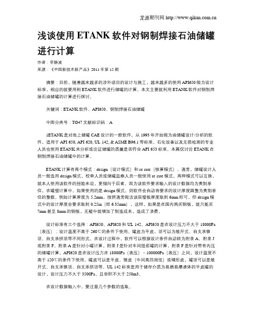
浅谈使用ETANK软件对钢制焊接石油储罐进行计算作者:李静波来源:《中国新技术新产品》2011年第15期摘要:目前,随着越来越多的涉外项目的设计与施工,越来越多的使用API650做为设计标准,相应的就要用到ETANK软件进行储罐的计算。
本文主要就利用ETANK软件对钢制焊接石油储罐的计算进行探讨。
关键词:ETANK软件、API650、钢制焊接石油储罐中图分类号:TG47文献标识码:A1ETANK是对地上储罐CAE设计的一款软件。
从1993年开始做为油储罐设计/分析的软件,适用于API-650, API-620, UL-142, & ASME B96.1等标准。
石化设备以及无损检测的专业人员也使用ETANK来分析或论证储罐的质量是否符合API-653标准。
本篇仅讨论ETANK在钢制焊接石油储罐中的计算。
ETANK计算有两个模式:design(设计模式)和re-rate(核算模式)。
通常,储罐设计人员一般选用design模式,校审人员或储罐监察人员一般使用re-rate模式,两种模式可以互换,就本人使用该软件的经验来说,更倾向于后者。
因为该软件要求输入的设计数据均为英制单位,在罐壁计算中,如果使用的是design模式,则软件会自动将要求的设计厚度圆整为英制单位的整数。
例如计算厚度为5.2mm,按照通常做法该层壁板厚度取到6mm即可,但design模式中的设计厚度会要求取到0.25in(即6.35mm),这样,如果是在国内购买钢板,就只能买7mm甚至8mm的钢板,无疑中就增加了制造成本,造成了浪费。
设计标准有三个选择:API650、API620和UL-142。
API650是在设计压力不大于18000Pa (表压);设计温度不高于260℃的条件下使用。
罐底为平底,顶可以为敞开式、自支承锥顶、自支承拱顶等不同形式。
在设计过程中,软件可以根据设计条件自动转为附录A、附录J 或附录F。
附录A是针对小罐计算,附录J是针对车间组装罐的计算,附录F是针对带有内压的储罐计算。
API-650储罐计算书
API 650储罐计算书内径:12.5米高度:9米设计内、外压: 2KPa/500PaTable of ContentsUser Input Data (3)Error Checker .LOG File (8)Wind, Material, Thickness & Weights (9)Roof Evaluation/Design & Appendix F (12)Seismic Analysis Results (13)Anchor Bolt Details (15)API-650 App I Grillage Review (16)API-650 App V External Pressure (17)Anchor Chair Calculations (18)Fluid Height Calculations (20)Wind Calculations (22)Thickness Calculations (24)Appendix F Calculations (27)Bolt Load Calculations (29)Seismic Analysis (31)Appendix V External Pressure (39)API-650/653 GENERAL TANK DATA :API-650 11th Edition, Addendum 3, Aug. 2011API Design Code ( 650 or 653 ) (650)Design Method (V, O, or A) ............................ O(V=variable, O=one foot, A=Appendix A)Run Objective (D=design, A=analyze) ................... ADesign Temperature ...............................(C ) 93.000Design Pressure at Top ....................(KPa ) 2.0000Shell Material ........................................ A-36Ratio of Normal Operating Pressure/Design Pressure [Fp] 0.40000Shell Design Stress [Sd] ..................(KPa ) 0.15995E+06 Shell Hydro Test Stress [St] ..............(KPa ) 0.17168E+06Tank Nominal Diameter [D] ........................(m. ) 12.500Tank Shell Height [HTK] ..........................(m. ) 9.0000Design Liquid Level [H] ..........................(m. ) 9.0000Liquid Specific Gravity [G] ........................... 0.85000Weight of Attachments/Structures..................(N. ) 30000.Distance down to Top Wind Girder .................(m. ) 0.00000 Joint Efficiency (App A or 653) [E] ................... 1.0000Wind Velocity .............................(M./sec. ) 37.500Insulation Thickness .............................(mm.) 40.000Insulation Density ........................(kg./cu.cm.) 0.22000E-03Include Annular Base Plate Details .................... YesInclude Wind Moment in Appendix F_4_2 Calculations .... YesNumber of Shell Courses (4)Shell Course # 1 Height ..........................(m. ) 2.2500Shell Course # 1 Thickness .......................(mm.) 10.000Shell Course # 1 Corrosion Allowance [CA] ........(mm.) 1.6000Shell Course # 2 Height ..........................(m. ) 2.2500Shell Course # 2 Thickness .......................(mm.) 10.000Shell Course # 2 Corrosion Allowance [CA] ........(mm.) 1.6000Shell Course # 3 Height ..........................(m. ) 2.2500Shell Course # 3 Thickness .......................(mm.) 10.000Shell Course # 3 Corrosion Allowance [CA] ........(mm.) 1.6000Shell Course # 4 Height ..........................(m. ) 2.2500Shell Course # 4 Thickness .......................(mm.) 10.000Shell Course # 4 Corrosion Allowance [CA] ........(mm.) 1.6000TANK SHELL COURSE MATERIALS :Shell Course # 1 Material Name ........................ A-36Shell Course # 1 Design Stress [Sd] .......(KPa ) 0.15995E+06 Shell Course # 1 Hydro Test Stress [St] ...(KPa ) 0.17168E+06 Shell Course # 1 Minimum Yield Stress .....(KPa ) 0.24821E+06 Shell Course # 1 Minimum Tensile Stress ...(KPa ) 0.39989E+06 Shell Course # 1 Maximum Thickness ..............(mm. ) 19.050Shell Course # 1 Material Grade .......................Shell Course # 1 Material Group (1)Shell Course # 2 Material Name ........................ A-36Shell Course # 2 Design Stress [Sd] .......(KPa ) 0.15995E+06 Shell Course # 2 Hydro Test Stress [St] ...(KPa ) 0.17168E+06 Shell Course # 2 Minimum Yield Stress .....(KPa ) 0.24821E+06 Shell Course # 2 Minimum Tensile Stress ...(KPa ) 0.39989E+06 Shell Course # 2 Maximum Thickness ..............(mm. ) 19.050Shell Course # 2 Material Grade .......................Shell Course # 2 Material Group (1)Shell Course # 3 Material Name ........................ A-36Shell Course # 3 Design Stress [Sd] .......(KPa ) 0.15995E+06 Shell Course # 3 Hydro Test Stress [St] ...(KPa ) 0.17168E+06 Shell Course # 3 Minimum Yield Stress .....(KPa ) 0.24821E+06 Shell Course # 3 Minimum Tensile Stress ...(KPa ) 0.39989E+06 Shell Course # 3 Maximum Thickness ..............(mm. ) 19.050Shell Course # 3 Material Grade .......................Shell Course # 3 Material Group (1)Shell Course # 4 Material Name ........................ A-36Shell Course # 4 Design Stress [Sd] .......(KPa ) 0.15995E+06 Shell Course # 4 Hydro Test Stress [St] ...(KPa ) 0.17168E+06 Shell Course # 4 Minimum Yield Stress .....(KPa ) 0.24821E+06 Shell Course # 4 Minimum Tensile Stress ...(KPa ) 0.39989E+06 Shell Course # 4 Maximum Thickness ..............(mm. ) 19.050Shell Course # 4 Material Grade .......................Shell Course # 4 Material Group (1)ANCHOR BOLT DETAILS :Anchor Bolt Diameter (optional) ..................(mm.) 44.450Threads per Unit Length ........................(1/mm.) 0.19685Bolt Allowable Stress .....................(KPa ) 0.15000E+06 Number of Anchor Bolts (optional) ..................... 20.000Bolt Yield Stress .........................(KPa ) 0.25000E+06 Bolt Offset from Mean Tank Diameter ..............(m. ) 0.10000Anchor Bolt Corrosion Allowance (optional) .......(mm.) 3.0000Wind Data :Kz parameter .......................................... 1.0400Kzt parameter ......................................... 1.0000Kd parameter .......................................... 0.95000Importance Factor (I) ................................. 1.0000Gust Factor (G) ....................................... 0.85000API-650 ROOF DETAILS SPECIFICATION :Roof Type (1-4) (4)(1=Supt Cone 2=Rafter Supt Cone 3=Cone 4=Dome 5=Umbrella)Angle Between Roof and Horizontal ................(deg) 24.610Net Area at Roof/Shell Junction [A] ...........(sq.mm.) 2000.5Thickness of Roof Plate ..........................(mm.) 10.000Roof Plate Corrosion Allowance ...................(mm.) 1.6000Weight of Snow on Roof ...........................(N. ) 0.00000 Roof Live Load ............................(N/M2 ) 1200.0---/ For General Roof, No Design /---Weight of Roof Plates ............................(N. ) 0.00000 Weight of Roof Framing ...........................(N. ) 0.00000 Pct of Weights Supported by Shell ..................... 0.00000---/ For Supported Cone Roof Design /---Preferred Rafter Type (W, WT, S, C) ...................Preferred Girder Type (W, WT, S, C) ...................Preferred Column Type (W, WT, S, C, DC, DI, P ) .......Roof Plate Material ................................... A-36Roof Plate Allowable Design Stress ........(KPa ) 0.15995E+06 Structural Member Material ............................ A-36Structural Member Allowable Design Stress..(KPa ) 0.15995E+06 Maximum Allowed Rafter Length ....................(m. ) -0.30788Maximum Allowed Girder Length ....................(m. ) -0.30788Center Column Cap Plate Diameter .................(m. ) 0.00000API-650 SEISMIC DATA (App E.) :Minimum Yield Strength of Bottom Plate .....(KPa 0.25000E+06 Minimum Yield Strength of Weld Material ....(KPa 0.25000E+06 Nominal Thickness of Bottom Plate (tb) ..........(mm. ) 8.0000Seismic Use Group (SUG)................................ 1.0000Friction Factor ....................................... 0.40000Importance Factor ..................................... 1.0000Initial Anchorage Type ................................ MEarthquake Type ....................................... SSite Class ............................................ 3.0000Spectral Acceleration Adjustment Coefficient (K) ...... 1.5000Scaling Factor (Q) .................................... 0.66700Transtiional Period (TL) .............................. 4.0000Mapped maximum earthquake for short periods (Ss) ...... 0.00000 Mapped maximum earthquake for 1 sec periods (S1) ...... 0.00000 Mapped maximum earthquake for 0 sec period (S0) ...... 0.00000 Non-ASCE peak ground acceleration (Sp) ................ 2.3000ASCE short period design acceleration parameter (SDS).. 0.00000 --- Site Specific Data ---Spectral acceleation parameter at 0 period (Sa0*) ..... 0.00000 Spectral acceleation parameter at any period (Sa*) .... 0.00000API-650 GRILLAGE REVIEW (App I.)Modulus of Elasticity of Bottom Plate .....(KPa ) 0.20200E+09 Corrosion Allowance added to Bottom Plate ......(mm. ) 1.5000Minimum Yield Strength of Bottom Plate ....(KPa ) 0.25000E+06 (Equal to Value from Seismic Data)SPECIFY ONE OF THE FOLLOWINGNominal Thickness of Bottom Plate ...............(mm. ) 8.0000(Equal to Value from Seismic Data )Maximum Allowed Spacing .........................(mm. ) 416.83API-650 External Pressure (App V.) :Specified External Pressure (Pe) ..........(N/M2 ) 500.00Elastic Modulus of Roof Plate Material ....(KPa ) 0.19900E+09 Bottom stiffener allow. compressive stress (KPa ) 0.15000E+06 Top stiffener allow. compressive stress ...(KPa ) 0.15000E+06 Nominal Thickness of Bottom Plate (tb) ..........(mm. ) 8.0000Smallest allowable tensile stress of roof,shell and stiffeners ....................(KPa ) 0.15000E+06 Roof Dish Radius ................................(m. ) 15.000Computation Control DirectivesROOF_PROJECTION_IN_WIND_MOMENT= YESSHELL_THICK_CONVERG_TOLERANCE= 0.12699999 mm.GENERATE_MESSAGE_FILE= NOCOSINE_CURVE_TOLERANCE= 0.30000001COSINE_CURVE_ITERATION_LIMIT= 100.00000WIND_GIRDER_SHELL_THICKNESS= MAXSHELL_SETTLEMENT_METHOD= FOURIER_SERIESCORRODED_NOZZLES= NO653_CORRODED_HYDROTEST_CASE= NOTHICKNESS_ROUNDUP_TO_NEAREST= 0.00000000 mm.PLATE_MATERIAL_DENSITY= 0.78500481E-02 kg./cu.cm. MODIFY_FLUID_HEIGHT_BY_PRESSURE= NOROUND_ANCHOR_BOLTS_BY= 4.0000000WIND_MOMENT_IN_APP_F= Sect_5.9.7.1FULL_SHELL_WEIGHT_IN_APP_F= YESUSE_P_FROM_F.4.1_ONLY_IN_F.6= YESUSE_NON_CORRODED_ROOF_WEIGHT_AS_DLR= NOYIELD_FOR_SEISMIC_IS_DERATED_FOR_TEMP= NOTANK(c) Intergraph CADWorx & Analysis Solutions, Inc. 2013C:\Users\yang\Desktop\法罗杰项目\大罐计算书\T-2303-zyh\新建文件夹\ Error Check Summary ReportFatal Errors 0Warning Messages 0Notes 0Error Checking CompletedWIND INFORMATIONAPI-650 11th Edition, Addendum 3, Aug. 2011Wind Velocity ............................(M./sec. ) 37.500Velocity Factor ...................................... 0.48866Wind Pressure ............................(KPa ) 0.96372Area Exposed to Wind .....................(m. **2) 131.22Sect 5.9.7.1 Wind Moment on Tank .........(N.m. ) 0.66347E+06 Wind Shear Force Acting on Tank ..........(N. ) 0.12646E+06MATERIAL PROPERTY INFORMATIONWind Girder Height Reduction Factor .................. 1.0000The following material properties have been modified inaccordance with API-650 (and API-653 where applicable).Course Material Design Test App MNumber Name Stress (Sd) Stress (St) Reduction(KPa ) (KPa )1 A-36 0.15995E+06 0.17168E+06 1.00002 A-36 0.15995E+06 0.17168E+06 1.00003 A-36 0.15995E+06 0.17168E+06 1.00004 A-36 0.15995E+06 0.17168E+06 1.0000SHELL COURSE THICKNESS DATA - One Foot MethodThickness Values for Three Cases MIN TEMPCOURSE DESIGN TEST USER (deg C )(mm. ) (mm. ) (mm. ) Status1 6.0000 6.0000 10.000 -8.8 PASS2 5.0000 5.0000 10.000 -8.8 PASS3 5.0000 5.0000 10.000 -8.8 PASS4 5.0000 5.0000 10.000 -8.8 PASSNote, "ANALYSIS" mode has been activated. From thispoint on, the user specified thicknesses will be usedfor all calculations. The above values for DESIGN andTEST thicknesses are for reference purposes only.SHELL COURSE ALLOWED FLUID HEIGHTSFluid Heights for Three CasesCOURSE DESIGN TEST REQUIRED(m. ) (m. ) (m. )1 26.107 28.328 9.00002 26.107 28.328 6.75003 26.107 28.328 4.50004 26.107 28.328 2.2500Maximum allowed fluid height of entire tank for:Design Thickness Case .................(m. ) 26.107Test Thickness Case .................(m. ) 28.328Required fluid height .................(m. ) 9.0000BASE PLATE DETAILS - SHELL WEIGHT & CENTER OF GRAVITYAnnular Base Plate Thickness .............(mm. ) 7.6000(from API-650 Table 5-1 plus corrosion)Annular Base Plate Width per 5.5.2 .......(mm. ) 670.40( 2 + ThkCrs1 + max[ 24, (390tb / sqrt(HG))] )Weight of Shell + Nozzles ................(N. ) 0.30269E+06 Total Weight of all Nozzles ..............(N. ) 0.00000 Center of Gravity (Shell+Nozzles) ........(m. ) 4.5000WIND OVERTURNING STABILITY CHECKCorroded Shell Weight + %Roof - Uplift ...(N. ) 0.19098E+06 wa .......................................(N./cm. ) 159.04Mw - moment due to wind (hor+ver) press ..(N.m. ) 0.75290E+06 Mpi - moment due to internal pressure ....(N.m. ) 0.15340E+07 Mf - moment due to tank liquid ...........(N.m. ) 0.39035E+07 Mdl - moment due to shell & roof .........(N.m. ) 0.18072E+07WIND GIRDER INFORMATIONFor "open top" tanks ...Required Section Modulus, Top Girder ...(mm. **3) 39767.Table 5-20 Detail, B value .............(mm. ) c 0.00Table 5-20 Shape name (if applicable)............... 4x3x.25Maximum Height of Unstiffened Shell ......(m. ) 138.59WIND GIRDER - TRANSFORMED SECTION METHODNumber of Intermediate Girders Reqd 0WEIGHT SUMMARY--------------Shell (Corroded) .............................(N. ): 228534. Shell (Non-Corroded) .........................(N. ): 272065. Annular Base Plate ...........................(N. ): 14701. Bottom Plate .................................(N. ): 76807. Nozzles ......................................(N. ): 0. Roof Plates ..................................(N. ): 106247. Roof Framing/Structure .......................(N. ): 0.Shell Attachments ............................(N. ): 30000. Insulation ...................................(N. ): 30621. Operating Fluid ..............................(N. ): 9187119. Water Weight .................................(N. ): 10808375.Operating Weight (Non-Corroded) ..............(N. ): 9717560. Test Weight (Non-Corroded) ...................(N. ): 11338816. Empty Weight (Non-Corroded) ..................(N. ): 530441.TANK(c) Intergraph CADWorx & Analysis Solutions, Inc. 2013TANK - Roof Design/Analysis DataAPI-650 11th Edition, Addendum 3, Aug. 2011SELF-SUPPORTING DOME ROOFRoof thickness per 5.10.6, 0.8D ......(mm. ): 5.7814Roof thickness per 5.10.6, 1.2D ......(mm. ): 7.8720Total weight of Roof Plates ...........(N. ): 0.10625E+06 (Based on user input thickness)User Specified Design Roof Load .......(KPa ): 2.1698(including user plate thickness)Computed Design Roof Load .............(KPa ): 2.1698(including user plate thickness)ROOF EVALUATIONS - Appendix FUplift force due to internal pressure..(N. ): 0.24543E+06 Total weight resisting uplift .........(N. ): 0.42191E+06Max Design Pressure, limited by uplift.(in of H2O ): 8.0954Max Design Pressure, limited by uplift.(KPa ): 2.0155(According to F.4.2)Max Design Pressure, roof/shell joint.(in of H2O ): 32.168Max Design Pressure, roof/shell joint.(KPa ): 8.0088(According to F.4.1)(Note, this value is limited by F.4.2 for further usage.)Compression Ring Failure Pressure .....(in of H2O ): 49.716Compression Ring Failure Pressure .....(KPa ): 12.378(According to F.6)Required Compression Areas, Roof/Shell JunctionArea as per Section F.5 ..............(mm. **2 ): 349.61Area as per Section 5.10.6, 0.8D ......(mm. **2 ): 231.37Area as per Section 5.10.6, 1.2D ......(mm. **2 ): 347.05FRANGIBLE ROOF-TO-SHELL JUNCTION AREA LIMITArea as per Section 5.10.2.6 ..........(mm. **2 ): 465.74Top Angle Requirement Per 5.1.5.9.e 2x2x1/4(This is a minimum angle size based solely on the tankdiameter. Other criteria may require a larger section.)TANK(c) Intergraph CADWorx & Analysis Solutions, Inc. 2013SEISMIC EVALUATION RESULTS - Appendix EAPI-650 11th Edition, Addendum 3, Aug. 2011Site-Specific Ground MotionDesign Fluid Weight (N. ) 0.91871E+07Sp -design level peak accel for nonASCE 2.3000Ss -MCE at period of 0.2 seconds 5.7500S0 -MCE at period of 0.0 seconds 2.3000S1 -MCD at period of 1.0 seconds 2.8750SDS-design spectral accel parameter 0.00000FA -acceleration based site coefficient 1.0000FV -velocity based site coefficient 1.3000TS - FvS1 / FaSs 0.65000TC -convective sloshing period (sec) 3.7200Ac -convective spectral accel parameter 0.00000 Ai -impulsive spectral accel parameter 0.00000 Wc -effective convective fluid weight(N. ) 0.29052E+07 Wi -effective impulsive fluid weight (N. ) 0.63741E+07 Vc -convective liquid base shear (N. ) 0.00000 Vi -impulsive liquid base shear (N. ) 0.00000 V -total design base shear (N. ) 0.00000VS -shear resistance (N. ) 0.38870E+07Xc -ring wall convective moment arm (m. ) 6.0467Xi -ring wall impulsive moment arm (m. ) 3.3750XCS-slab convective moment arm (m. ) 6.5034XIS-slab impulsive moment arm (m. ) 5.3604WS -shell+appurtenances weight (N. ) 0.33269E+06 Wrs-roof, framing 10% snow weight (N. ) 0.00000 Mrw-ringwall overturning moment (N.m. ) 0.00000 Ms -slab overturning moment (N.m. ) 0.00000AV -vertical acceleration parameter 0.00000 Ge -effective specific gravity 0.85000wa -resisting annulus force (N./cm. ) 192.27wt -tank + roof weight at shell base (N./cm. ) 84.719J -the anchorage ratio 0.00000L -reqd min annular plate projection (m. ) 0.00000Wab-Minimum anchorage resistance (N./cm. ) -22.220N -number of anchor bolts required 16Pab-anchor seismic design load (N. ) -5453.5 Sc -shell compressive stress (KPa ) 1008.6 Sa -shell allowable stress (KPa ) 42964.Height of sloshing wave (m. ) 6.2825 Required Freeboard (m. ) 4.3978Course Hoop Stress Hoop Allowable(KPa ) (KPa )1 46852. 0.21273E+062 35139. 0.21273E+063 23426. 0.21273E+064 11713. 0.21273E+06Seismic Evaluation Summary.Seismic shell stress check passed.Base shear within limits.Hoop stress within allowable.TANK(c) Intergraph CADWorx & Analysis Solutions, Inc. 2013ANCHOR BOLT DETAILS - Section 5.12API-650 11th Edition, Addendum 3, Aug. 2011Case Uplift Allowable Load/Bolt(N. ) Bolt Stress (N. )(KPa )Design Pressure : 0.00000 103419. 0.00000Test Pressure : 0.00000 137892. 0.00000Failure Pressure : 0.18473E+07 250000. 92367.Wind Loading : 0.00000 200000. 0.00000Seismic OPE : 0.00000 200000. 0.00000Design Press + Wind Load : 0.00000 137892. 0.00000 Design Press + Seismic OPE : 0.00000 200000. 0.00000 Frangibility Pressure : 0.41235E+07 250000. 0.20618E+06ANCHOR BOLT RESULTS - Section 5.12Case Number Bolt Bolt Stressof Bolts Diameter (KPa )(mm. )Design Pressure : 20 44.450 0.Test Pressure : 20 44.450 0.Failure Pressure : 20 44.450 88276.Wind Loading : 20 44.450 0.Seismic OPE : 20 44.450 0.Design Press + Wind Load : 20 44.450 0.Design Press + Seismic OPE : 20 44.450 0.Frangibility Pressure : 20 44.450 197042.Final Anchor Bolt Spacing .............. (m. ) 1.99Specified number of user bolts is sufficient.Specified user bolt diameter is sufficient.TANK(c) Intergraph CADWorx & Analysis Solutions, Inc. 2013API-650 APPENDIX I.7.3 GRILLAGE CHECKAPI-650 11th Edition, Addendum 3, Aug. 2011Uniform Pressure "p" ..................(KPa ): 91.18717 Computed Grillage Spacing ....................(mm.): 416.83304 Allowed Bottom Deflection ....................(mm.): 3.25000 Computed Bottom Deflection ...................(mm.): 1.40932TANK(c) Intergraph CADWorx & Analysis Solutions, Inc. 2013EXTERNAL PRESSURE RESULTS - Appendix VAPI-650 11th Edition, Addendum 3, Aug. 2011DL roof plate dead load ..............(N/M2 ) 769.8 PR design external pressure ..........(N/M2 ) 2169.8 For a Dome Roof:Required thickness of roof plate .....(mm. ) 7.001 Length of roof considered in region ..(mm. ) 196.456 Required area of roof/shell joint ....(mm. **2) 803.622 Required area of top stiffener ......(mm. **2) 0.000 Length of shell included (top) .......(mm. ) 150.031 Length of shell included (bottom) ....(mm. ) 150.031Transformed Shell Height .............(m. ) 9.000Elastic Buckling Check V.8.1.1Buckling Check Ok, exceeds 0.19 ................ 0.829Ps design ext press for shell .......(N/M2 ) 925.311 Ps(max) max design external pressure (N/M2 ) 8174.512 ts(min) min shell for design ext press (mm. ) 4.195Stiffeners are not required for external pressure.TANK(c) Intergraph CADWorx & Analysis Solutions, Inc. 2013Anchor Chair Cap Input Values:Thickness of Gusset Plates j 20.000 mm.Width of Gussets at Top Plate twdt 180.000 mm.Width of Gussets at Base Plate bwdt 40.000 mm.Height of Gussets Hg 240.000 mm.Height of Gussets plus top Plate thickness h 264.000 mm. Distance between Gussets g 100.000 mm.Dist. from Bolt Center to Gusset (Rg/2) cg 50.000 mm. External Corrosion Allowance Ca 2.0000 mm.Top Plate allowable stress S 250000.0 KPaNumber of Gussets per bolt ng 2Bottom Shell Course Thickness 10.000 mm.Shell Course Corrosion Allowance 1.6000 mm.Thickness of Tank Baseplate m 8.000 mm.Thickness of Top Plate c 24.000 mm.Radial Width of the Top Plate b 180.000 mm.Circumferential Width of the Top Plate a 280.000 mm. Anchor Bolt Diameter d 44.45 mm.Anchor Chair Cap and Gusset Plate Analysis Results:Required Thickness of Top Chair Cap Plate per AISI:P Bolt Loade Bolt eccentricity (center of bolt to shell OD)Sb Allowable Bending Stress ( 1.5 * S )g Distance between Gussetsd Bolt DiameterTop Chair Cap Plate Required Thickness per AISI [Tc]:= ( P /( Sb * e ) * ( 0.375 * g - 0.22 * d ))?+ c= (206175/(374999*95.000)*(0.375*100.00-0.22*44.450))?2.000= 14.6663 mm.Stress in the Top Plate at given Thickness [Stpl]:= P( 0.375 * b - 0.22 * d ) / e / ( c - Ca )?= 206175 (0.375*100.000 - 0.22*44.450 )/95.000 / (24.000 -2.000 )? = 124304.9 KPa , must be less than 375000.0 KPaRequired Gusset Thickness per AISI:Gusset Plate Thickness is the greater of( 0.5 in (12mm), 0.04( hg ))= max( 12.700 , 0.04( 240.000 ) ) + Ca= 14.700 mm.For gusset plates the following must also be true:Gusset Thickness * Average Gusset Width >= (P/1000)/25= ( 20.000 - 2.000 ) * 120.000 > ( 206.175 / 25 ) Passed= 2160.000 > 8.247 PassedLocal Stress at the Top Plate per AISI, including axial Stress [S]:= P*e/t瞇1.32*Z/(1.43*a*h?(R*t)+ (4(a)(h)?.333 + 0.031 /(R*t)?= 206175*95.00/8.40瞇1.32*0.94/(1.43*280.00*(264.00)?(6251.60*8.40) + (4*280.00 (264.00 )?0.333 + 0.031/(6251.60 *8.40 )?= 397491.9 KPaIntermediate Value [Z]:= 1/[(0.177*a*m/(R*t)?*(m/t)?+ 1]= 1/[(0.177*280.000*8.000/(6251.600*8.400)?*(8.000/8.400)?1]= 0.942Radial Distance [e]:= ( Dc - Ds ) / 2= ( 12690.000 - 12500.000 ) / 2= 95.000 mm.TANK(c) Intergraph CADWorx & Analysis Solutions, Inc. 2013Determine Maximum allowed Fluid Heights:For Course # 1, Operating CaseAllowed fluid height above this course based on the 1ft method= (Td - ca)Sd/(2.6 * D * G ) + X/12= (0.3937 - 0.0630 )23199.32 /(2.6 * 41.0 * 0.850 ) + 12.000 /12 = 85.651 ft. [26.107 m.]For Course # 1, Hydro Case, not corrodedAllowed fluid height above this course based on the 1ft method= (Td - ca)Sd/(2.6 * D * G ) + X/12= (0.3937 - 0.0000 )24900.65 /(2.6 * 41.0 * 1.000 ) + 12.000 /12 = 92.941 ft. [28.328 m.]For Course # 2, Operating CaseAllowed fluid height above this course based on the 1ft method= (Td - ca)Sd/(2.6 * D * G ) + X/12= (0.3937 - 0.0630 )23199.32 /(2.6 * 41.0 * 0.850 ) + 12.000 /12 = 85.651 ft. [26.107 m.]For Course # 2, Hydro Case, not corrodedAllowed fluid height above this course based on the 1ft method= (Td - ca)Sd/(2.6 * D * G ) + X/12= (0.3937 - 0.0000 )24900.65 /(2.6 * 41.0 * 1.000 ) + 12.000 /12 = 92.941 ft. [28.328 m.]For Course # 3, Operating CaseAllowed fluid height above this course based on the 1ft method= (Td - ca)Sd/(2.6 * D * G ) + X/12= (0.3937 - 0.0630 )23199.32 /(2.6 * 41.0 * 0.850 ) + 12.000 /12 = 85.651 ft. [26.107 m.]For Course # 3, Hydro Case, not corrodedAllowed fluid height above this course based on the 1ft method= (Td - ca)Sd/(2.6 * D * G ) + X/12= (0.3937 - 0.0000 )24900.65 /(2.6 * 41.0 * 1.000 ) + 12.000 /12 = 92.941 ft. [28.328 m.]For Course # 4, Operating CaseAllowed fluid height above this course based on the 1ft method= (Td - ca)Sd/(2.6 * D * G ) + X/12= (0.3937 - 0.0630 )23199.32 /(2.6 * 41.0 * 0.850 ) + 12.000 /12 = 85.651 ft. [26.107 m.]For Course # 4, Hydro Case, not corrodedAllowed fluid height above this course based on the 1ft method= (Td - ca)Sd/(2.6 * D * G ) + X/12= (0.3937 - 0.0000 )24900.65 /(2.6 * 41.0 * 1.000 ) + 12.000 /12 = 92.941 ft. [28.328 m.]Appendix M Yield Stress reduction factor, M.3.6 [Mfact]:= Yield Reduction Factor * Fy / Fyamb= 1.000 * 36000.6 / 30000.0= 1.000 Must be less than or equal to 1.0Total Design External Pressure Loading per V.7 [Pr]:= max[ DL + (Lr or S) + 0.4Pe, DL + Pe + 0.4(Lr or S)]= max[ 16.078 + max[25.063 , 0.000 ] + 0.4 * 10.443 ,16.078 + 10.443 + 0.4 * max[25.063 , 0.000 ]]= max[ 45.318 , 36.546 ]= 45.318 psf [2169.822 N/M2]Moment about shell-to-bottom joint [MDL]:= ( Shell Weight + Attachement Weight + Framing Weight * % )D/2 = ( 58263.3 + 6744.6 + 0.0 * 0.00 )41.0 /2= 1333003.2 ft.lb [1807232.5 N.m.]Design Pressure per F.4.1 [P]:= (0.962 * A * Fy * tan(theta))/(D^2) + 0.245 * DLR/D^2= (0.962*3.101*36000.0*tan(24.61))/(41.0^2)+0.245*20060/41.0^2= 32.168 in. of water [817.077 mm. of water]= 1.162 psi [8.009 KPa]Note: Design Pressure was less than maximum computed per F.4.1Moment about shell-to-bottom joint [MDLR]:= ( Roof Weight )D/2= ( 20060.4 )41.0 /2= 411344.4 ft.lb [557684.3 N.m.]TANK(c) Intergraph CADWorx & Analysis Solutions, Inc. 2013Wind Load Calculations:Wind velocity factor 5.2.1 [Vfact]:= ( Wind Velocity / 120 )^2= ( 83.9 / 120 )^2= 0.489Vertical projected wind area of tank [VArea]:= Tank Height * Tank Diameter= 29.53 * 41.01= 1210.940 ft^2 [112.500 m.^2]Velocity pressure per 5.9.7.1 [p]:= 0.00256 * Kz * Kzt * kd * V^2 * I * G + 5.0= 0.00256 * 1.040 * 1.000 * 0.950 * 83.885^2 * 1.000 * 0.850 + 5.0 = 20.128 psf [963.737 N/M2]Wind moment on shell [Moment]:= Wind Pressure * Wind Area * Tank Height/2= 20.128 * 1210.9 * 29.53 /2= 0.35985E+06 ft.lb. [0.48787E+06 N.m.]Vertical projected wind area of Dome/Umbrella roof:Radius of the apex:= 0.8 D= 0.8 * 41.010= 32.808 ft. [10.000 m.]Half angle between tank and apex radii:= asin( D / (2 * Rapex) )= asin( 41.010 / (2 * 32.808 ) )= 38.683 deg.Area of the sector:= 2 * Half angle / ( 2 pi ) * ( pi * Rapex^2 )= 2 * 0.675 / ( 2 * 3.142 ) * ( 3.142 * 32.808^2 )= 726.706 ft.^2 [67.513 m.^2]Height from apex to chord:= Rapex * cos(Half angle)= 32.808 * cos(0.675 )= 25.611 ft. [7.806 m.]Area of triangle below the chord line:= Apex height * D/2= 25.611 * 41.010 /2= 525.161 ft.^2 [48.789 m.^2]Dome/Umberlla roof area:= Sector area - Triangle area= 726.706 - 525.161= 201.545 ft.^2 [18.724 m.^2]Area Exposed to Wind:= Wind area of tank + Wind area of roof= 1210.940 + 201.545= 1412.485 ft.^2 [131.224 m.^2]Wind Moment at the base including the dome/umbrella roof [Total Moment]:= Moment + ( Wind P * Roof Area( Tank Height + dome Height/3)) = 359851.9 + ( 20.128 * 201.5 ( 29.5 + 7.20 /3))= 489369.469 ft.lb. [663467.562 N.m.]Wind shear force acting on the tank:= Wind Pressure * (tank area + roof area)= 20.128 * 1412.5= 0.28431E+05 lbf. [0.12646E+06 N.]TANK(c) Intergraph CADWorx & Analysis Solutions, Inc. 2013。
- 1、下载文档前请自行甄别文档内容的完整性,平台不提供额外的编辑、内容补充、找答案等附加服务。
- 2、"仅部分预览"的文档,不可在线预览部分如存在完整性等问题,可反馈申请退款(可完整预览的文档不适用该条件!)。
- 3、如文档侵犯您的权益,请联系客服反馈,我们会尽快为您处理(人工客服工作时间:9:00-18:30)。
N/A 0.00 N/A 0.00 N/A 0.00 N/A 0.00 N/A 0.00 N/A 0.00 2.53
19,965.94
NLtecho= Ttecho =
Ttecho n = Vtt= Ptt=
Rings= Aa=
NLanillo= TWALL-A1 = TWALL-A1n = TWALL-A2 = TWALL-A2n = TWALL-A3 = TWALL-A3n = TWALL-A4 = TWALL-A4n =
Density of the Sheet of Steel, Kg/m3 OUTPUTS
THICKNESS WALLS SHEET Number of Rings with Standard Sheets
Area of A Ring, m2 Number of Sheets Needed by ring
Minimum Thickness of sheet in Ring 1, mm Thickness of Sheet I Ring 1 Nominal, mm Minimum Thickness of sheet in Ring 2, mm Thickness of Sheet on Ring 2 Nominal, mm Minimum Thickness of sheet in Ring 3, mm Thickness of Sheet on Ring 3 Nominal, mm Minimum Thickness of sheet in Ring 4, mm Thickness of Sheet on Ring 4 Nominal, mm
2,562.34 90,476.20 676,970.02 21,491.11 54,530.51 2,616,869.73
16,117.17 676,921.19 2,562,146.71
2,562.15
2.50
15,714.24 659,998.16 2,498,093.04
2,498.09
TWALL-A6 = TWALL-A6n =
TWALL-A7 = TWALL-A7n =
TWALL-A8 = TWALL-A8n =
TWALL-A9 = TWALL-A9n = TWALL-A10 = TWALL-A10n =
Vct=
Pct=
Minimum Thickness of sheet in Ring 5, mm Thickness of Sheet on Ring 5 Nominal, mm Minimum Thickness of sheet in Ring 6, mm Thickness of Sheet on Ring 6 Nominal, mm Minimum Thickness of sheet in Ring 7, mm Thickness of Sheet on Ring 7 Nominal, mm Minimum Thickness of sheet in Ring 8, mm Thickness of Sheet on Ring 8 Nominal, mm Minimum Thickness of sheet in Ring 9, mm Thickness of Sheet on Ring 9 Nominal, mm Minimum Thickness of sheet in Ring 10, mm Thickness of Sheet on Ring 10 Nominal, mm
A P I 6 2 0
Write input Data Only on not colored cells
Module 14
ATMOSPHERICAL TANK CALCULATOR
CALCULATION S
ACCORDING WITH API 650 - FT BY FT METHOD
INLETS GENERAL DATA
NLpiso= Tpiso=
Tpiso n = Vpt= Ppt=
Volumen=
Peso Total=
Thicknesses: Sheets of Conical Roof Number of Sheets Needed for the Roof minimal needed Thickness of Roof's sheet, INCHES minimal needed Thickness of Roof's sheet, mm Nominal Thickness of Roof's sheet, mm
Pd Td D H G Sd C.A.
q CAPt
Design Pressure ftwc= Height of the tank (full of water) + 12 ftwc (ft of water column)
Design Temperature, ºC Diameter of the Tank, feet Height of the Tank (Calculations Limits = 80 ft), feet specific Gravity of the Stored Fluid (Water=1) Allowable Working stress at Designs conditions, Psi Corrosion thickness, inch Angle of Inclination of the Roof with regard to the horizontal one, degrees
396.00 93.00 60.00 32.00 1.00 23,200.00 0.0625 25.00
20.00 8.00
14.86
7,901.42
4 140.09
10 6.8821
5.00 5.5157
4.00 4.1494
4.00 2.7831
4.00
TWALL-A5 = TWALL-A5n =
Volume of the Roof of the Tank, m3 Weight of the Roof of the Tank, Kg
Thicknesses: Sheets of Floor Number of Sheets Needed for the Floor
minimal needed Thickness of Floor's sheets, INCHES minimal needed Thickness of Floor's sheets, mm Nominal Thickness of Floor's sheets, mm Volume of the Floor of the Tank, m3 Total Weight of the Floor of the Tank, Kg: Total volume of Stored Water, m3 Ft3 gallons Barrels (U.S. Liquid) Total Weight of the Empty Tank, Kilograms Total Weigh of the Tank Full of Water, Kilograms
Net Tanks Capacity (Barrels): Net Tanks Capacity (Gallons):
Net Tanks Capacity (Liters): Net Tanks Capacity (Mts3):
18.00 0.35 9.02 6.35 1.70 13,424.16
18.00 0.31 7.94 10.00 2.68 21,140.41
Capacity needed of the Tank, cubic meters
LENGTH WIDTH
STANDARD SHEET Length of the sheet, feet Width of the sheet, feet Area of Standard Sheet, m2
AREA STD S: DENFra bibliotekITYNominal Tanks Capacity (Barrels): Nominal Tanks Capacity (Gallons):
Nominal Tanks Capacity (Liters): Nominal Tanks Capacity (Mts3):
Percent of Volume of Air in the Tank(%):