光束光学功率计OPM-360和国产激光功率计价格
VIAVI SmartClass OLP-8x 光学功率计操作指南说明书
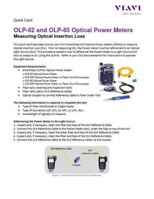
VIAVI Solutions Quick CardOLP-82 and OLP-85 Optical Power Meters Measuring Optical Insertion LossThis quick card describes how to use VIAVI SmartClass OLP Optical Power Meters (OPMs) to measure Optical Insertion Loss (OIL). Prior to measuring OIL, the Power Meter must be referenced to an Optical Light Source (OLS). This procedure explains how to Reference the Power Meter to a Light Source and how to measure OIL using the OLP-8x. Refer to your OLS documentation for instructions to operate the Light Source.Equipment Requirements:•SmartClass OLP-8x Optical Power Meter:o OLP-82 Optical Power Metero OLP-82P Optical Power Meter w/ Patch Cord Microscopeo OLP-85 Optical Power Metero OLP-85P Optical Power Meter w/ Patch Cord Microscope•Fiber optic cleaning and inspection tools•Fiber optic patch cord (Reference Cable)•Optical Coupler to connect Reference Cable to Fiber Under TestThe following information is required to complete the test:•Type of Fiber (Multimode or Single Mode)•Type of Connectors (SC UPC, SC APC, LC UPC, etc.)•Wavelength of signal(s) to measureReferencing the Power Meter to the Light Source:1.Inspect and, if necessary, clean the fiber end face of the OLP Reference Cable.2.Connect the OLP Reference Cable to the Power Meter port, under the flap on top of the OLP.3.Inspect and, if necessary, clean the other fiber end face of the OLP Reference Cable.4.Inspect and, if necessary, clean the fiber end face of the OLS Reference Cable.5.Connect the OLP Reference Cable to the OLS Reference Cable via the coupler.Figure 1: Connecting the OLP to an OLS for ReferenceFigure 2: OLP-82P Layout Figure 3: Power Meter Results screen6.Press the Power button to turn on the OLP and display the Home screen.7.Tap the Power Meter icon to launch the power meter.8.Tap the dBm/dB Display Unit soft key and set the Display Units to dB.The soft key will be labeled dBm, when the unit is set to dB in the Results Display.9.Tap the Wavelength soft key and select the wavelength to measure.10.Confirm that the OLS laser is on, and tap the SET REF soft key to reference the PowerMeter to the OLS. The signal level will change to 00.00 dB.11.Repeat steps 9 and 10 for all wavelengths to be tested.12.Disconnect the Reference Cable from the coupler. Do not disconnect the Reference Cable from theOLP port or power off the OLP until all OIL testing is complete. If the OLP is powered off or the fiber is disconnected from the OLP, you must reference the OLP and OLS again.VIAVI SolutionsContact Us +1 844 GO VIAVI (+1 844 468 4284) To reach the VIAVI office nearest you, visit /contacts.© 2018 VIAVI Solutions Inc.Product specifications and descriptions in this document are subject to change without notice.Measuring Insertion Loss:If you are performing an Optical Insertion Loss test and the OLP-8x has been referenced to an OLS, the Reference Cable should already be connected to the OLP-8x and the OLP-8x should be powered on and in the Power Meter Results view.1. If the interface to the Fiber under Test (FUT) is a patch cord, connect the patch cord to an opticalcoupler with the same connector type. 2. Inspect and, if necessary, clean the FUT connected to the coupler or OPP. 3. Inspect and, if necessary, clean the fiber end face of the Reference Cable.4. Connect the OLP Reference Cable to the coupler or OPP leading to the light source.Figure 4: Connecting the OLP to an OPP or coupler5. Tap the Wavelength soft key and select the wavelength to measure.6. View the Relative Power Level (dB) in the Results Display at the top of the screen.Figure 5: Optical Insertion Loss Results7. Repeat steps 5 and 6 for all wavelengths to be tested.8. Disconnect the Reference Cable from the FUT. Do not disconnect the Reference Cable from theOLP or power off the OLP until all testing is complete. If the fiber is disconnected, you must reference the Power Meter again. 9.Repeat steps 1 through 8 for all fibers to be tested.。
网上竞价项目需求书货物类
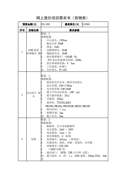
10.输入孔径:5mm
完全响应
3
电源
数量:2规格配置:
完全响应
1.触摸屏:交互电容触摸屏
2.电压量程:20mV - 200V
3.电流量程:IonA - IA
4.基本准确度:0. 012%
5.宽带噪声:2mVrms(典型值)
6.扫描类型:线性,对数,双 线性,双对数
7.读数缓存>250,000
5.中标人不能交货的,需偿付不能交货部分货款的10%作为 违约金。
一、采购项目报价表
项目名称
分项报价清单
序号
产品名称
品牌/规格型号
数量
单价
(人民币元)
总价
(人民币元)
1
2
合计金额(元):
小写:
大写:
报价要求
1)报价超出最高限价无效。
2)报价必须是人民币报价,并请注明是含税或免税。进口产品可报人民币 免税价,如未报免税价则一律按含税价处理。进口产品申请办理免税时若 以外币结算的,如须换算为对应的外币,以截标当日中国银行总行首次发 布的外币对人民币的现汇卖出价进行换算,汇率风险将由投标人承担,结 算以实际支付汇率为准,最终实结算金额不超过该项目中标金额。
网上竞价项目需求书(货物类)
预算金额/元
230,000
最高限价/元
213560
序号
货物名称
需求参数
1
1550波段 单频激光 器
数量:1
规格配置:
1.中心波长:1550nm
2.输出功率:50mW
3.线宽:IkHz
4.边模抑制比:50dB
5.偏振消光比:20dB
6.相对强度噪声:-105dB∕Hz
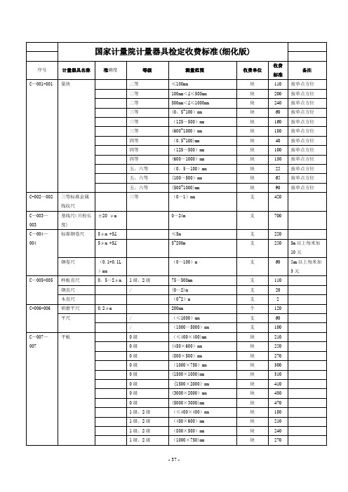
国家计量院计量器具检定收费标准
310
每增加一个量限,加收150元
0。1级及以下
(35~110)kV
0.05级
(0~35)kV
基本量限
165
每加一个量限加收70元,超35kV的检定加收130元
(0。005~0。001)级
10V~35kV
基本量限
310
每增加一个量限,加收220元
(0。01~0。05)级
10V~35kV
基本量限
220
每增加一个量限,加收110元
(0。01~0。05)级
(35~110)kV
块
90
按单点方位
C-002—002
三等标准金属线纹尺
三等
(0~1)mm
支
420
C—003—003
基线尺(只检长度)
±20 μm
0~24m
支
700
C—004—004
标准钢卷尺
5μm +5L
≤5m
支
220
5μm +5L
5~200m
支
250
5m以上每米加10元
钢卷尺
(0.1+0.1L)mm
(0~100)m
电子水平仪
(1+A/50)mm/m
±500个数
台
260
C—021—021
投影仪
100mm
台
310
C-022—022
测高仪
≤600mm
台
270
>600mm
台
530
0。01
0~10mm
台
220
C-023—023
接触式干涉仪
0。05μm, 0。1μm, 0。2μm
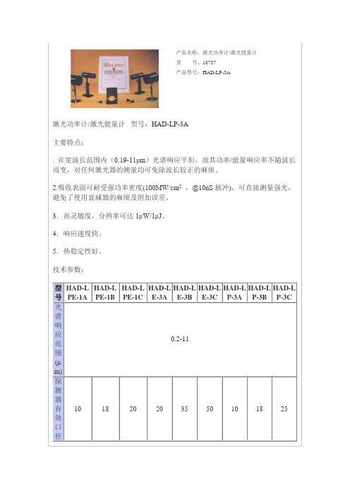
产品名称激光功率计激光能量计
18
20
20
35
50
10
18
25
响应时间(s)
0.4
0.4
2
0.4
0.4
0.4
0.4
0.4
2
功率测量分辨率(µW)
1
10
100
1
10
100
最大可测功率(W)
2
10
50
2
10
50(200)
能量测量分辨率(µJ)
1
10
100
1,10
10
10
最大可测能量(J)
2
10
20
2-20
20
20
指示器类型
3½LED
不确定度(±%)20x90
85x220x230
配套探测器型号
IP-210
IP-220
IP-1025
IP-520
IP-535
IP-550
IP-210
IP-220
IP-1025
特点
功率能量计
功率能量计
功率能量计
能量计
能量计
能量计
功率计
功率计
功率计
〖关闭〗
3.高灵敏度,分辨率可达1μW/1μJ。
4.响应速度快。
5.热稳定性好。
技术参数:
型号
HAD-LPE-1A
HAD-LPE-1B
HAD-LPE-1C
HAD-LE-3A
HAD-LE-3B
HAD-LE-3C
HAD-LP-3A
HAD-LP-3B
HAD-LP-3C
光谱响应范围(µm)
0.2-11
探测器有效口径(mm)
上海滑德斐湃Low Cost360°无人机机载超声测得计入介绍膊单册说明书

w w w . slamt ec. comRPLIDAR A2 Low Cost 360 Degree Laser Range Scanner Introduction and DatasheetModel: A2M12OPTMAG16K2022-04-08 rev.1.0CONTENTS (1)INTRODUCTION (3)S YSTEM CONNECTION (3)M ECHANISM (4)S AFETY AND S COPE (6)D ATA O UTPUT (7)H IGH S PEED S AMPLING P ROTOCOL AND C OMPATIBILITY (7)A PPLICATION S CENARIOS (8)SPECIFICATION (9)M EASUREMENT P ERFORMANCE (9)L ASER P OWER S PECIFICATION (9)O PTICAL W INDOW (10)C OORDINATE S YSTEM D EFINITION OF S CANNING D ATA (10)C OMMUNICATION INTERFACE (11)MISC (14)SELF-PROTECTION AND STATUS DETECTION (15)SDK AND SUPPORT (16)MECHANICAL DIMENSIONS (17)REVISION HISTORY (18)APPENDIX (19)I MAGE AND T ABLE I NDEX (19)IntroductionThe RPLIDAR A2M12 is the next generation low cost 360 degree 2D laser scanner (LIDAR) solution developed by SLAMTEC. It can take up to 16000 samples of laser ranging per second with high rotation speed. And equipped with SLAMTEC patented OPTMAG technology, it breakouts the life limitation of traditional LIDAR system so as to work stably for a long time.The system can perform 2D 360-degree scan within a 12-meter range. The generated 2D point cloud data can be used in mapping, localization and object/environment modeling.The typical scanning frequency of RPLIDAR A2M12 is 10Hz(600rpm), and the frequency can be freely adjusted within the 5-15Hz range according to the specific requirements. With the 10Hz scanning frequency, the sampling rate is 16kHz and the angular resolution is 0.225°.Due to the improvements in SLAMTEC hardware operating performance and related algorithm, RPLIDAR A2M12 works well in all kinds of indoor environment and outdoor environment without direct sunlight. Meanwhile, before leaving the factory, every RPLIDAR A2M12 has passed the strict testing to ensure the laser output power meet the eye-safety standard of IEC-60825 Class 1.System connectionThe RPLIDAR A2M12 consists of a range scanner core and the mechanical powering part which makes the core rotate at a high speed. When it functionsnormally, the scanner will rotate and scan clockwise. And users can get the range scan data via the communication interface of the RPLIDAR and control the start, stop and rotating speed of the rotate motor via PWM.Range Scanner CoreCommunicationand PowerInterface MechanicalPowering PartFigure 1-1 RPLIDAR System CompositionThe RPLIDAR A2M12 comes with a rotation speed detection and adaptive system. The system will adjust the angular resolution automatically according to the actual rotating speed. And there is no need to provide complicated power system for RPLIDAR. In this way, the simple power supply schema saves the BOM cost. If the actual speed of the RPLIDAR is required, the host system can get the related data via communication interface.The detailed specification about power and communication interface can be found in the following sections.MechanismThe RPLIDAR A2M12 is based on laser triangulation ranging principle and adopts the high-speed vision acquisition and processing hardware developed by SLAMTEC. The system ranges more than 16000 times per second.During every ranging process, the RPLIDAR emits modulated infrared laser signal and the laser signal is then reflected by the object to be detected. The returning signal is then sampled by vision acquisition system in RPLIDAR and the DSPembedded in RPLIDAR starts processing the sample data and outputs distance value and angle value between object and RPLIDAR via communication interface.dFigure 1-2 The RPLIDAR Working SchematicWhen drove by the motor system, the range scanner core will rotate clockwise and perform the 360-degree scan for the current environment.Figure 1-3 The Obtained Environment Map from RPLIDAR ScanningSafety and ScopeThe RPLIDAR A2M12 system uses a low power infrared laser as its light source, and drives it by using modulated pulse. The laser emits light in a very short timeframe which can ensure its safety to human and pet, and it reaches Class I laser safety standard. Complies with 21 CFR 1040.10 and 1040.11 except for deviations pursuant to Laser Notice No. 50, dated June 24, 2007.Caution : Use of controls or adjustments or performance of procedures other than those specified herein may result in hazardous radiation exposure.The modulated laser can effectively avoid the interference from ambient light and sunlight during ranging scanning process, which makes RPLIDAR work excellent in all kinds of indoor environment and outdoor environment without direct sunlight.*Note :The LIDAR scan image is not directly relative to the environment showed here. Illustrative purpose only.Class IData OutputDuring the working process, the RPLIDAR will output the sampling data via the communication interface. And each sample point data contains the information in the following table. If you need detailed data format and communication protocol, please contact SLAMTEC.Figure 1-4 The RPLIDAR Sample Point Data InformationFigure 1-5 The RPLIDAR Sample Point Data FramesThe RPLIDAR outputs sampling data continuously and it contains the sample point data frames in the above figure. Host systems can configure output format and stop RPLIDAR by sending stop command. For detailed operations please contact SLAMTEC.High Speed Sampling Protocol and CompatibilityThe RPLIDAR A2M12 adopts the newly extended high speed sampling protocol for outputting the 16000 times per second laser range scan data. Users areData TypeUnitDescriptionDistance mm Current measured distance value between the rotating core of the RPLIDAR and the sampling point Heading degree Current heading angle of the measurement Start Flag (Bool) Flag of a new scanChecksumThe Checksum of RPLIDAR return data…(d ሾn −1ሿ,θሾn −1ሿ)(d ሾn ሿ,θሾn ሿ) (d ሾ0ሿ,θሾ0ሿ) (d ሾ1ሿ,θሾ1ሿ)…Start FlagA new scanrequired to update the matched SDK or modify the original driver and use the new protocol for the 16000 times per second mode of RPLIDAR A2M12. Please check the related protocol documents for details.RPLIDAR A2M12 is compatible with all communication protocols used by previous RPLIDAR products. Users can directly replace the previous model of RPLIDAR and use it directly on the original system.Application ScenariosThe RPLIDAR can be used in the following application scenarios:General robot navigation and localizationEnvironment scanning and 3D re-modelingService robot or industrial robot working for long hoursHome service /cleaning robot navigation and localizationGeneral simultaneous localization and mapping (SLAM)Smart toy’s localization and obstacle avoidanceMeasurement PerformanceFigure 2-1 RPLIDAR PerformanceNote: the triangulation range system resolution changes along with distance. Laser Power SpecificationFigure 2-2 RPLIDAR Optical SpecificationNote: the laser power listed above is the peak power and the actual average power is much lower than the value.Optical WindowTo make the RPLIDAR A2M12 working normally, please ensure proper space to be left for its emitting and receiving laser lights when designing the host system. The obscuring of the host system for the ranging window will impact the performance and resolution of RPLIDAR A2M12. If you need cover the RPLIDAR A2M12 with translucent materials or have other special needs, please contact SLAMTEC about the feasibility.Optical WindowFigure 2-3 RPLIDAR Optical WindowYou can check the Mechanical Dimensions chapter for detailed window dimensions.Coordinate System Definition of Scanning DataThe RPLIDAR A2M12 adopts coordinate system of the left hand. The dead ahead of the sensors is the x axis of the coordinate system; the origin is the rotating center of the range scanner core. The rotation angle increases as rotating clockwise. The detailed definition is shown in the following figure:Figure 2-4 RPLIDAR Scanning Data Coordinate System DefinitionCommunication interfaceThe RPLIDAR A2M12 uses separate 5V DC power for powering the range scanner core and the motor system. And the standard RPLIDAR A2M12 uses XH2.54-5P male socket. Detailed interface definition is shown in the following figure:Figure 2-5 RPLIDAR Power Interface Definitionθ ሾ0,360)Interface LeadRedXH2.54-5PVCCTXRXGND MOTOCT LFigure 2-6 RPLIDAR External Interface Signal DefinitionPower Supply InterfaceRPLIDAR A2M12 takes the only external power to power the range scanner core and the motor system which make the core rotate. To make the RPLIDAR A2M12 work normally, the host system needs to ensure the output of the power and meet its requirements of the power supply ripple.Figure 2-7 RPLIDAR Power Supply SpecificationNote: When the lidar is connected to the power supply, there is a process of charging the input capacitor. The maximum transient current of charging canreach 2500mA. After stable operation, the working current does not exceed 600mA.Data communication interfaceThe RPLIDAR A2M12 takes the 3.3V-TTL serial port (UART) as the communication interface. The table below shows the transmission speed and the protocol standard.Figure 2-8 RPLIDAR Serial Port Interface SpecificationsNote: the RX input signal of A2M12is current control type. In order to ensure the reliable signal identification inside the system, the actual control node voltage of this pin will not be lower than 1.6v.Scanner Motor ControlThe RPLIDAR A2M12 is embedded with a motor driver which has speed tuning feature. Users can control the start, the stop and the rotating speed for the motor via MOTOCTL in the interface. MOTOCTL can be supplied using PWM signal with special frequency and duty cycle, and in this mode, the rotating speed is decided by the duty cycle of the input MOTOCTL PWM Signal.The following table describes the requirement for the input PWM signal of MOTOCTL:Figure 2-9 RPLIDA Specification for PWM Signal of MOTOCTLNote: the typical value is tested when the scanner rotating frequency is 10Hz. With the same rotating speed, the PWM duty cycle of every RILIDAR A2M12 may vary slightly. If a precise rotating speed is required, users can perform a closed-loop control.If the host system only need to control the start and stop of the motor, please use the direct current signal in high level and low level to drive MOTOCTL. Under this condition, when the MOTOCTL is the low level signal, the RPLIDAR A2M12 will stop rotating and scanning; when the MOTOCTL is the high level signal, the RPLIDAR A2M12 will rotated at the highest speed.MISCFigure 2-10 RPLIDAR MISC SpecificationTo ensure the laser of RPLIDAR always working in the safety range (<3mW) and avoid any other damage caused by device, the RPLIDAR comes with laser power detection and sensor healthy check feature. It will shut down the laser and stop working automatically when any of the following errors has been detected. Laser transmit power exceeds limited valueLaser cannot power on normallyScan speed of Laser scanner system is unstableScan speed of Laser scanner system is too slowLaser signal sensor works abnormallyThe host systems can check the status of the RPLIDAR via the communication interface and restart the RPLIDAR to try to recover work from error.To facilitate the usage of RPLIDAR A3 in the product development and speed up the development cycle for users, SLAMTEC has provided the Framegrabber plugin in RoboStudio for testing and debugging as well as the SDK available under Windows, x86 Linux and Arm Linux. Please contact SLAMTEC for detail information.Figure 4-1 the Framegrabber Plugin in RoboStudioThe mechanical dimensions of the RPLIDAR A2M12 are shown as below:Figure 5-1 RPLIDAR Mechanical DimensionsNote: the 4 M3 screws in the bottom should be no longer than 4mm, or the internal module would be damaged.Image and Table IndexF IGURE 1-1RPLIDAR S YSTEM C OMPOSITION (4)F IGURE 1-2T HE RPLIDAR W ORKING S CHEMATIC (5)F IGURE 1-3T HE O BTAINED E NVIRONMENT M AP FROM RPLIDAR S CANNING (6)F IGURE 1-4T HE RPLIDAR S AMPLE P OINT D ATA I NFORMATION (7)F IGURE 1-5T HE RPLIDAR S AMPLE P OINT D ATA F RAMES (7)F IGURE 2-1RPLIDAR P ERFORMANCE (9)F IGURE 2-2RPLIDAR O PTICAL S PECIFICATION (9)F IGURE 2-3RPLIDAR O PTICAL W INDOW (10)F IGURE 2-4RPLIDAR S CANNING D ATA C OORDINATE S YSTEM D EFINITION (11)F IGURE 2-5RPLIDAR P OWER I NTERFACE D EFINITION (11)F IGURE 2-6RPLIDAR E XTERNAL I NTERFACE S IGNAL D EFINITION (12)F IGURE 2-7RPLIDAR P OWER S UPPLY S PECIFICATION (12)F IGURE 2-8RPLIDAR S ERIAL P ORT I NTERFACE S PECIFICATIONS (13)F IGURE 2-9RPLIDA S PECIFICATION FOR PWM S IGNAL OF MOTOCTL (14)F IGURE 2-10RPLIDAR MISC S PECIFICATION (14)F IGURE 3-1 THE L IDARS P LUGIN IN R OBO S TUDIO (16)F IGURE 4-1RPLIDAR M ECHANICAL D IMENSIONS (17)Manufacturer: SHANGHAI SLAMTEC CO., LTD.Address: D-501 Shengyin Tower, 666 Shengxia Rd., Shanghai, ChinaMade in China。
OPM 10000 mini 系列 光功率计 说明书

型号 OPM1000mini_DET-UV OPM1000mini_DET-SL OPM1000mini_DET-ST OPM1000mini_DET-IR OPM1000mini_DET-IT0.78~1.10.78~1.10.4~1.1光谱范围(um)0.2~1.10.4~1.1最大输入功率(W/cm2)1.51.51.5(带OD3衰减器)0.151.5最大输入功率(mW/cm2)1.51.5(不带衰减器) 0.151.51.5校准不确定度 3.5%@200~390nm 3.5%@400~940nm 3.5%@400~940nm 3.5%@780~1700nm 3.5%@800~1650nm (不带衰减器) 1.75%@391~940nm 7%@941~1100nm 7%@941~1100nm 7%@1701~1800nm 7%@1701~1800nm7%@941~1100nm校准不确定度 14%@200~350nm 1.75%@400~940nm 1.75%@400~940nm 8.75%@780~910nm 8.75%@780~910nm (带OD3衰减器) 7%@351~390nm 7%@941~1100nm 7%@941~1100nm 3.5%@911~1700nm 3.5%@911~1700nm7%@1701~1800nm1.75%@391~940nm7%@1701~1800nm7%@941~1100nm均匀性 ±3.5% ±3% ±3% ±2% ±3%线形 ±2% ±1.5% ±1% ±0.5% ±1%饱和电流(mA/cmcm2)9 4504503.50.02>0.1A/W ≥0.2A/W ≥0.1A/W相应度 ≥0.04A/W>0.1A/W400~1100nm 850~1700nm 800~1700nm250~1100nm400~1100nm>0.5A/W>0.5A/W >0.8A/W >0.8A/W最大相应度 >0.25A/WNEP(W/√HZ) 1.9X10⁻¹² 6.5X10⁻¹³ 1.5X10⁻¹⁴ 0.7X10⁻¹² 0.7X10⁻¹²Ge材料 Si Si Si Ge5/103/5/10有效面积直径mm 5/10 5/105/10有效面积形状 圆型 圆型 方型 圆型 方型探头工作温度 0~50°C 0~50°C 0~50°C 0~50°C 0~50°C探头工作电压 DC5V(±5%) DC5V(±5%) DC5V(±5%) DC5V(±5%) DC5V(±5%)通讯接口 RS232/USB RS232/USB RS232/USB RS232/USB RS232/USB型号 OPM1000mini_DET-IG0.8~1.65光谱范围(um)最大输入功率(W/cm2)(带OD3衰减器) 1.5最大输入功率(mW/cm2)(不带衰减器) 1.5校准不确定度 3.5%@800~1650nm(不带衰减器)校准不确定度 8.75%@800~900nm(带OD3衰减器) 3.5%@901~1650nm均匀性±3%线形 ±1%饱和电流(mA/cmcm2) 350相应度 ≥0.1A/W800~1600nm最大相应度 >0.9A/WNEP(W/√HZ) 3.0X10⁻¹⁴材料 InGaAs有效面积直径mm 3/5有效面积形状 圆型探头工作温度 0~50°C探头工作电压 DC5V(±5%)通讯接口 RS232/USBOPM1000mini_DET-UV OPM1000mini_DET-SL OPM1000mini_DET-IG OPM1000mini_DET-IR 尺寸示意图模拟输出SMA连接器安装支架固定孔(M4)探测器窗口通讯电缆 &电源电缆 端口衰减片滑片探测器窗口通讯电缆 &电源电缆 端口OPM1000mini_DET-ST OPM1000mini_DET-IT 尺寸示意图OPM_DET_HOLDER 尺寸示意图探头部件示意图增强光纤适配器优势比较适配器能大幅度提高测量准确性.探头型号 描述OPM1000mini_DET-□1-□2-□3-□4□1->探测器类型UV SL ST IR IT IG□2->有效面积(mm)3 5 10□3->衰减器OD0(无衰减片)O D3(30dB)□4->计算机接口R(RS232) U(USB)有效组合OPM1000mini_DET-UV-5-OD0/OD3-R/UOPM1000mini_DET-SL-5-OD0/OD3-R/UOPM1000mini_DET-SL-10-OD0/OD3-R/UOPM1000mini_DET-ST-10-OD0/OD3-R/UOPM1000mini_DET-IR-3-OD0/OD3-R/UOPM1000mini_DET-IG-3-OD0/OD3-R/UOPM1000mini_DET-IR-5-OD0/OD3-R/UOPM1000mini_DET-IG-5-OD0/OD3-R/UOPM1000mini_DET-IT-10-R/U探头附件型号 描述OPM_DET-FA2 裸光纤适配器座OPM_DET_FH1 裸光纤适配器夹具OPM_DET_FC_S 简易FC适配器OPM_DET_SMA_S 简易SMA适配器OPM_DET_ST_S 简易ST适配器OPM_DET_LC_S 简易LC适配器OPM_DET_SC_S 简易SC适配器OPM_DET_U125_S 简易1.25mm通用适配器OPM_DET_U25_S 简易2.5mm通用适配器OPM_DET_FA 增强光纤适配器安装座OPM_DET_SMA_A 增强SMA光纤适配器OPM_DET_FC_A 增强FC光纤适配器OPM_DET_LC_A 增强LC光纤适配器OPM_DET_SC_A 增强SC光纤适配器OPM_DET_U125_A 增强1.25mm通用光纤适配器OPM_DET_U25_A 增强2.5mm通用光纤适配器OPM_DET_CORE_VIS 增强光纤适配器可见光波段适配器(430~700nm) OPM_DET_CORE_NIR 增强光纤适配器近红外波段适配器(650~1000nm) OPM_DET_CORE_IR 增强光纤适配器红外波段适配器(1000~1600nm) OPM_DET_HOLDER 探头固定片OPM_ACC-2 便携箱标准配置RS232版本:探头 X1 探头防尘帽 X1 RS232电缆 X1 探头电源适配器 X1 驱动光盘 X1 使用说明及保修卡 X1USB版本:探头 X1 探头防尘帽 X1 USB电缆 X1 驱动光盘 X1 使用说明及保修卡 X1。
ophir vega光功率计误差
ophir vega光功率计误差(原创版)目录1.Ophir Vega 光功率计简介2.光功率计误差的概念与影响因素3.Ophir Vega 光功率计的误差类型4.如何减小 Ophir Vega 光功率计的误差5.结论正文1.Ophir Vega 光功率计简介Ophir Vega 光功率计是一款高精度的光功率测量仪器,广泛应用于光通信、光纤网络、半导体照明等领域。
它可以测量光信号的功率、波长、光强度等参数,为光通信系统的研发、生产和维护提供重要技术支持。
2.光功率计误差的概念与影响因素光功率计误差是指测量结果与真实值之间的巟值。
光功率计误差的影响因素包括仪器本身的精度、测量环境的温度、湿度、灰尘等因素。
此外,操作人员的操作习惯和技能水平也会对误差产生影响。
3.Ophir Vega 光功率计的误差类型Ophir Vega 光功率计的误差主要分为系统误差和随机误差两种类型。
系统误差:也称为偏差,是由测量仪器的精度、测量方法等因素引起的,其大小和符号在一定条件下具有规律性。
随机误差:也称为噪声,是由环境因素、操作人员技能水平等因素引起的,其大小和符号在一定条件下没有规律性。
4.如何减小 Ophir Vega 光功率计的误差为了减小 Ophir Vega 光功率计的误差,可以采取以下措施:(1)选择高精度的光功率计:购买时选择知名品牌、高精度的光功率计,以提高测量准确度。
(2)定期校准:定期将光功率计送至专业机构进行校准,确保测量结果的准确性。
(3)合理操作:在测量过程中,应遵循操作规程,避免因操作不当导致的误差。
(4)控制环境因素:在测量过程中,应尽量保持环境温度、湿度稳定,避免灰尘等杂物影响测量结果。
5.结论Ophir Vega 光功率计在光通信领域具有重要应用价值,但其测量结果可能受到误差的影响。
Fluke 3X360R 3X360G 三维激光距离仪用户手册说明书
3X360R, 3X360GThree Plane LasersUsers Manual09/2020© 2020 Fluke Corporation. All rights reserved. Specifications are subject to change without notice.LIMITED WARRANTY AND LIMITATION OF LIABILITYThis Fluke product will be free from defects in material and workmanship for three years from the date of purchase. This warranty does not cover fuses, disposable batteries, or damage from accident, neglect, misuse, alteration, contamination, or abnormal conditions of operation or handling. Resellers are not authorized to extend any other warranty on Fluke’s behalf. To obtain service during the warranty period, contact your nearest Fluke authorized service center to obtain return authorization information, then send the product to that Service Center with a description of the problem.THIS WARRANTY IS YOUR ONLY REMEDY. NO OTHER WARRANTIES, SUCH AS FITNESS FOR A PARTICULAR PURPOSE, ARE EXPRESSED OR IMPLIED. FLUKE IS NOT LIABLE FOR ANY SPECIAL, INDIRECT, INCIDENTAL OR CONSEQUENTIAL DAMAGES OR LOSSES, ARISING FROM ANY CAUSE OR THEORY. Since some states or countries do not allow the exclusion or limitation of an implied warranty or of incidental or consequential damages, this limitation of liability may not apply to you.Fluke Corporation Fluke Europe B.V. ООО «Флюк СИАЙЭС»P.O. Box 9090 P.O. Box 1186 125167, г. Москва,Everett, WA 98206 5602 BD Eindhoven Ленинградский проспект дом 37,U.S.A. The Netherlands корпус 9, подъезд 4, 1 этаж11/99Table of ContentsTitle Page Introduction (1)How to Contact Fluke (1)Safety Information (1)Product Familiarization (3)Features (3)Lasers and Optical Glass (4)Controls (5)Check Product Accuracy (6)Cone Accuracy (6)Horizontal Leveling Accuracy (8)Vertical Accuracy (10)90 Degree Accuracy (12)Accessories (14)3X360 Magnetic L-bracket (14)Maintenance (15)Clean the Product (15)Replacing Battery (15)RBP5 Rechargeable Battery (16)Housing Glass Insert (16)Specifications (17)3X360R, 3X360G Users Manual3X360R, 3X360GIntroduction IntroductionThe 3X360R, 3X360G Three Plane Lasers (the Product) are battery powered, self-leveling, professional grade instruments. The 3X360R emit solid red line lasers. The 3X360G emit solid green line lasers. The 3X360R and 3X360G also emit vertical and horizontal point lasers 90 degrees from the Product. Use the Product to lay out reference points to align targets horizontally, vertically, or diagonally.NoteIf the laser beam is difficult to see, use either the XLD+ or SLDR or SLDG Laser Detector to accurately determine the location of the laser. See the XLD+ or SLDR or SLDG Users Manual.How to Contact FlukeTo contact Fluke, call one of the following telephone numbers:• Technical Support USA: 1-800-44-FLUKE (1-800-443-5853)• Calibration/Repair USA: 1-888-99-FLUKE (1-888-993-5853)• Canada: 1-800-36-FLUKE (1-800-363-5853)• Europe: +31 402-675-200• Japan: +81-3-6714-3114• Singapore: +65-6799-5566• China: +86-400-921-0835• Brazil: +55-11-3530-8901• Anywhere in the world: +1-425-446-5500Or, visit the PLS website at .To view, print, or download the latest manual supplement, visit .Safety InformationA Warning identifies conditions and procedures that are dangerous to the user. A Caution identifies conditions and procedures that can cause damage to the Product or the equipment under test.To prevent eye damage and personal injury:• Read all safety information before you use the Product.• Carefully read all instructions.• Do not alter the Product and use only as specified, or the protection supplied by the Product can be compromised.• Do not use the Product if it operates incorrectly.• Do not use the Product if it is altered or damaged.• Use the Product only as specified or hazardous laser radiation exposure can occur.• Do not look into the laser. Do not point laser directly at persons or animals or indirectly off reflective surfaces.• Do not look directly into the laser with optical tools (for example, binoculars, telescopes, microscopes). Optical tools can focus the laser and be dangerous to the eye.• Do not open the Product. The laser beam is dangerous to eyes.• Battery contains hazardous chemicals that can cause burns or explode. If exposure to chemicals occurs, clean with water and get medical aid.• Do not disassemble the battery.• Repair the Product before use if the battery leaks.• The battery door must be closed and locked before you operate the Product.• Remove the battery if the Product is not used for an extended period of time, or if stored in temperatures above 50 °C.If the battery is not removed, battery leakage can damage the Product.• Replace the battery when the low battery indicator shows to prevent incorrect measurements.• Use only Fluke approved power adapters to charge the battery. Refer to RBP5 manual for additional safety information and instructions.• Do not short the battery terminals together.• Do not disassemble or crush battery cells and battery packs.• Do not keep cells or battery in a container where the terminals can be shorted.3X360R, 3X360GUsers ManualTable 1 is a list of the symbols that can be used on the Product or in this manual.Table 1. SymbolsNoteIn colder climates, the Product needs sufficient time to warm up to achieve the stated accuracy measurements. Turn on both the horizontal and vertical lasers and wait 3 minutes before you take a measurement. When you move the Product between environments with large differences in ambient temperature, allow for an additional adjustment time.3X360R, 3X360GProduct Familiarization Product FamiliarizationThe manual explains features for multiple models. Because models have different features and accessories, not all of the information in the manual may apply to your Product.FeaturesUse Table 2 to identify the features and standard accessories of your Product.Table 2. FeaturesIn3X360R, 3X360GControls ControlsTable 4 lists the Controls of the Product.3X360R, 3X360GUsers ManualCheck Product AccuracyCone Accuracy1. Place the laser on a flat surface going in one direction.2. Turn on the horizontal beam and project on the parallel wall. You will need to have a set distance between (a,b)which will be referred to as "D" with the horizontal beam.illustration 1illustration 23. Rotate the laser 180 degrees horizontally and place at point b, as seen above .4. Turn on the horizontal beam and adjust the laser height so the center of the beam is aligned with mark b.3X360R, 3X360GCone Accuracyillustration 35. Mark c directly above or below a.6. Measure the distance between these two marks (a,c). If the measurement value is greater then the corresponding E value, take to your service provider.73X360R, 3X360GUsers ManualHorizontal Leveling AccuracyIt is important to conduct an accuracy check at the expected working distance for the specific use case and is illustrated in Table 6.1. Place the laser on a flat surface going in one direction. You will need to have a set distance between (a,b) which will bereferred to as "D".2. Turn on the horizontal beam and mark (a,b)a is 3.2ft (1m) away from laserillustration 13. Once “D” is identified based on illustration 1, rotate the laser 90 degrees horizontally as seen below.4. Mark c and calculate the distance between c,b and this is F.illustration 2893X360R, 3X360GHorizontal Leveling Accuracy5. Rotate the laser 180 degrees horizontally as seen below.6. Mark d and calculate the distance between d,b and this is E.illustration 37. Rotate the laser 270 degrees horizontally as seen below.8. Mark e and calculate the distance between e,b and this is G.9. If any of the values are greater than the respective E,F,G column values, take to your service provider.illustration 4103X360R, 3X360G Users ManualVertical AccuracyIt is important to conduct an accuracy check at the expected working distance for the specific use case and is illustrated in Table 7.1. Place the laser on a flat surface that is even in both directions across.a.The height of the room used should reflect with the corresponding values under column "J"illustration 13X360R, 3X360GVertical Accuracy2. Turn on both vertical beams +a. Mark two short lines where both vertical beams intersect on points (a,b) and (c,d).illustration 23. Pick up and rotate the laser 180 degrees then position the vertical beams with existing (a,b) marks. These marks on the ground become (e,f).4. On the ceiling, mark two short lines (g,h)illustration 35. Measure the distance between (h,d) and this value is K.6. Measure the distance between (c,g) and this value is L7. Review your applicable row for vertical distance is less than or equal to K & L. If greater than the values, take to your service provider.1190 Degree AccuracyChecking 90 degree accuracy requires a large open floor space. Distances A,B,C can be chosen based on your application and distance to use.1. Place the laser on a smooth, flat and stable surface that is level in both directions.2. Turn on the side vertical beam.3. Mark the center of the beam at three locations on the ground, as seen below at (a,b,c) and (b) should be the midpointof the entire line length.illustration 14. Move the laser to mark b and turn on both vertical beams +5. Position the beam crossing precisely at mark b.6. Mark location d along the front vertical beam at set distance C.illustration 2127. Rotate the laser 90 degrees horizontally8. Position the front and side vertical beams with (b).9. Mark e and measure the distance (D) beweetn (c,e).10. If the value is greater than D values, take to your service provider.illustration 3133X360R, 3X360GUsers ManualAccessoriesTable 9 is a list of the accessories available for the Product.Table 9. AccessoriesModel Description PN PLS HGI3X360R PLS Housing glass insert for PLS 3x360R5204916 PLS HGI3X360G PLS Housing glass insert for PLS 3x360G5214800 PLS 3X360 MLB Magnetic L-bracket w/ micro and elevation adj5214817 PLS 3X360 CB Ceiling bracket used w/ PLS 3X360 MLB5214821 PLS XLD+PLS Universal rotary/line laser detector w/ clamp5221059 PLS 3X360 HC PLS 3X360 blow mold hard case5221067 PLS RBP5Li-ion battery for handheld lasers w/ charging cord5023322 PLS RRT4Red magnetic reflective target5022629 PLS GRT4Green magnetic reflective target5022634 Note: PLS 3X360 is not compatible with PLS BP5 alkaline battery pack (PN 5031952)3X360 Magnetic L-bracket and Ceiling BracketPLS 3X360 CBFigure 13X360 MLB Magnetic L-bracketHorizontal rotation360◦Horizontal rotation precision adjustment YesElevation adjustment Max. 2.79 in (71 mm)Elevation adjustment lock*YesLaser level mounting screw1/4-20 UNC male threadedTripod mounting hole1/4-20 UNC female threaded, 5/8-11 UNC female threaded Wall hanging hole Max. 0.53 in (13.5 mm)Dimensions (H x W x D)Approx. 5.9 x 3.3 x 5.4 in (150 x 87.3 x 137 mm) Weight Approx. 0.86 lb (0.39 kg)Note: * the elevation adjustment lock provides 2X friction.143X360R, 3X360GMaintenance 3X360 CB Ceiling BracketCompatibility3X360 MLBClamp opening Max. 0.118 in (3 mm)Dimensions (H x W x D)Approx. 9.84 x 2.52 x 2.4 in (250 x 64 x 61 mm)Weight Approx. 0.84 lb(0.38 kg)MaintenanceTo maintain the Product, clean the case and optical glass and replace the batteries.The laser beam is dangerous to the eyes.Clean the ProductClean the case with a damp cloth and a weak soap solution.To clean the optical glass, use a pressurized can of air or a dry nitrogen-ion gun, if available, to blow off particulates from the optical surfaces.Replacing BatteryReplace the battery when the battery indicator LED is red.To install or replace RBP5 (Li-ion) using AA battery tray is not commended due to extremely short battery life (see Figure 2):1. Press down on the latch 1.2. While pressing down, pull back on battery pack and remove.3. Reinstall recharged battery pack.153X360R, 3X360GUsers ManualRBP5 Rechargeable BatteryFigure 3Housing Glass InsertIf the optical glass is damaged, replace the housing glass insert. See Table 6 for the part number to order for your Product. To replace the housing glass insert (see Figure 4):1. Remove the four housing glass insert screws2. Pull out the the tower insert and glass insert.3. Replace the insert and re-fasten screws.123Figure 4. Housing Glass Insert Replacement163X360R, 3X360GSpecifications SpecificationsSpecifications PLS 3X360R PLS 3X360GBattery (RBP5)Lithium-ion, 3.6 V, 5200 mAhBattery Life, Continuous Use (typical)3 beams: ≥ 9 hours1 beam: ≤ 30 hours3 beams: ≥ 5 hours1 beam: ≤ 17 hoursLine Fan AngleHorizontal360°Front Vertical360°Side Vertical360°Working RangeWithout line detector65 ft (20 m)115 ft (35 m) With line detector165 ft (50 m)210 ft (65 m) Accuracy± 5/64 in @ 33 ft (± 2 mm @ 10 m) Laser LevelingSystem Automatic PendulumRangeSelf-leveling: ≤ 4°Out of self-levelling: > 6°Leveling time≤ 3 sec TemperatureOperating14 °F to 122 °F (-10 °C to 50 °C)StorageWith Battery: -4 °F to 122 °F (-20 °C to 50 °C) Without Battery: -13 °F to 158 °F (-25 °C to 70 °C)Relative Humidity 0 % RH to 90 % RH (0 °C to 35 °C) 0 % RH to 75 % RH (35 °C to 40 °C) 0 % RH to 45 % RH (40 °C to 50 °C)IP rating IP 54Drop test 3.28 ft (1 m)Battery status indication 100%, 75%, 50%, 25% and low batterySize (H x W x L) w/ RBP5 5.12 in x 3.58 in x 5.25 in (13 cm x 9.09 cm x 13.33 cm) Weight (with battery) 1.76 lbs (0.8 kg)Li-ion battery safety IEC 62133Laser Safety Class 2 (IEC 60825-1) Light Source Semiconduction laser diodeMax Output Power< 1 mWWavelengthRed635 nm ± 10 nmGreen520 nm ± 10 nm Electromagnetic Compatibility (EMC)International IEC 61326-1Korea (KCC) Class A Equipment (Industrial Broadcasting & Communication Equipment) [1][1] This product meets requirements for industrial (Class A) electromagnetic wave equipment and the seller or user should take notice of it. This equipment is intended for use in business environments and is not to be used in homes.USA (FCC) 47 47 CFR 15 subpart B. This product is considered an exempt device per clause 15.103.17。
- 1、下载文档前请自行甄别文档内容的完整性,平台不提供额外的编辑、内容补充、找答案等附加服务。
- 2、"仅部分预览"的文档,不可在线预览部分如存在完整性等问题,可反馈申请退款(可完整预览的文档不适用该条件!)。
- 3、如文档侵犯您的权益,请联系客服反馈,我们会尽快为您处理(人工客服工作时间:9:00-18:30)。
光束光学功率计OPM-360和国产激光功率计价格
标题:光纤光学功率计OPM37LAN厂家和激光器功率计参数库号:《RL099300 》价格::百度搜【润联网】查询
主要技术参数:
主要特点和优点高达28.6 Gb/s 的码型发生、误码分析和BER 测试能力经校准的集成经校准的集成压力生成技术,满足多种标准压力接收机灵敏度和时钟恢复抖动容限测试要求最高100MHz 的正弦抖动(SJ)频率随机抖动(RJ) 有界不相关抖动(BUJ) 正弦干扰(SI) 扩展频谱时钟 PCIe 2.0和3.0接收机测试 IEEE 802.3ba 和32G光纤通道测试加压力的电眼图测试包括: PCI Express 10/40/100Gb 以太网
SFP+/SFI XFP/XFI OIF/CEI 光纤通道(FC8, FC16, FC32) SATA USB 3.0* InfiniBand (SDR, QDR, FDR, EDR) 抖动裕量(Margin)测试、抖动容限一致性模板测试快速输入上升时间/高输入带宽错误检测器,准确分析信号完整性物理层测试套件,支持模板测试、抖动峰值、BER轮廓和Q因子分析,使用标准或用户自定义抖动容限模板库进行全方位测试集成的眼图和BER相关分析抖动分离及定位(Jitter Map)选件系统丰富的抖动解析–支持长码型(如PRBS-
标题:数字激光功率计和激光器功率计参数库号:《RL099301 》价格::百度搜【润联
网】查询
主要技术参数:
主要特点和优点支持最高1.6Gb/s 数据码型发
生/ 误码检测,快速、精确地对数据通信系统
进行参数测试PRBS或者8Mb长度用户自定
义码型可以灵活的调试和验证任何数字信号内
建极精确的时钟源可调节幅度、偏置、逻辑阈
值和端接等参数,为接收机测试提供灵活多样
的信号激励差分或单端IO 确保满足所有通信
总线标准BitAlyzer® 误码分析快速理解被测系
统的误码率极限、评估确定性和随机性误码,
详细的码型相关误码分析,进行突发(Burst)分
析以及无误码时间间隔分析等自动化眼图测量
和快速眼图模板测试提供了对被测系统快速的
信号完整性分析ANSI 标准的抖动测量 (RJ、
DJ 和TJ),能够测量BER 在10-12时的TJ
和RJ支持Q 因子分析,揭示眼高和BER 之
间的关系BER 轮廓揭示眼图和BER 的关系,
可以将轮廓导出为眼图模板内建的前向误码纠
错 (Forward Error Correction) 可以仿真通信系
统FEC 设计的性能误码定位及分析 (Error
Maping) 揭示信号出现误码的位置和原因
标题:激光镭射功率测试仪和激光功率计参数库号:《RL099304 》价格::百度搜【润联
网】查询
主要技术参数:
详细介绍硅光二极管最大可测量50.00mW
相对值最大锁定,数据平均(20数据序列平
均)直读波长(488,633,670,780,
830nm) RS-232C接口
标题:激光镭射功率测试仪和精密功率计参数库号:《RL099305 》价格::百度搜【润联
网】查询
主要技术参数:
激光功率计特征:超高速针不到1秒的响应时间读取电源检测器 PH系列热电堆和光学探测器大屏幕液晶显示 77 x 58 mm 17.5 mm 位背光(带交流整流器)指针有三种显示功能普通尾部(表示速度)条柱显示还可以保持高值和低值一键导航可直接访问或长按访问主要功能耗电量低 4节 AA 碱性电池可连续使用300小时。