Kestrel4000手持式风速仪-NK4000便携式气象站
德尔塔4000自动电 funeral性因素测试装置配件说明书

AccessoriesTESTING LARGE SPECIMENSThe resonating inductor expands the capacitance range of the DELTA automated insulation power factor test sets. The resonating inductor is a self-contained, air-insulated tool which allows the user to perform capacitance and dissipation factor tests on high-capacitance items such as large motors, large generators and long cable runs.A manual tuning wheel on the resonating inductor varies the inductance to tune the parallel circuit for minimum load current.Resonating Inductor includes:High-voltage interface cable, 8 ft (2.4 m) Ground interconnect lead, 8 ft (2.4 m)Inductor return cable, 8 ft (2.4 m), with connector Ground lead, 15 ft (4.6 m)Cable bag Instruction manual30012-1330991-11001-8024702-518313670600a_UGSPECIFICATIONSMaximum Capacitive Load1 µF , at 60 Hz - 12kV1.2 µF , at 50 Hz - 12 kV 1.33 µF , at 45 Hz - 12 kV(from DELTA4000 variable frequency source)Dimensions 38.7 H x 21.4 W x 25.3 D in. 983 H x 543 W x 641 D mm Weight280 lbs (127 kg)Megger provides adapter kits that offer solutions for users who already own an older style or competitor’s resonating inductor and need to connect to a DELTA4000. Our C/N 1002-455 includes:High-voltage interface cable, 8 ft (2.4 m) Inductor return cable, 8 ft (2.4 m), with connector Adapter kit box, unterminated Connector assembly30012-141001-8021002-231-11002-506Cat. No. 670600-1Cat. No. 1002- 455For more information about these products,visit our website FIELD & LAB CALIBRATIONThe CAL4000 is designed for use in performing calibration adjustments of the DELTA4000 series of instruments. Together with provided software, it allows for proper adjustment of critical measurements within the DELTA4000 including: tan delta (PF), capacitance, voltage, current, watts and other measurements. Operators are able to perform the calibration adjustments within a 20 to 30 minute timeframe. This tool does not replace a traceable report, only a method to bring the DELTA4000 to within specified accuracy.When field testing, the reliability of test results is critical in determining the true condition of the transformer or related asset. In order toconfirm proper operation of the DELTA4000 and its nominal accuracy, Megger has developed a set of capacitors that provide this confirmation of results. The capacitors come in a set of three where two capacitors contain one nominal tan delta (PF) value as to simulate a typical test result. The third capacitor is of a higher value and serves a second purpose as a TTR add-on function capability. All units include a field transit case for easy store and protection.Capacitors can be purchased individually should the specific need arise.SPECIFICATIONS HV Capacitors10 nf, 10 kV – C/N 36610100 pf, 10 kV – C/N 36610-11000 pf, 10 kV – C/N 36610-2Transit case for capacitor with set of 3 above C/N 36610-CCCat. No. 2002-137Cat. No. 36610-KIT2Shown here: TTR cap, 2 ref caps, test hook, test clip, transit caseHV Reference Standard, Capacitance and Tan Delta (PF)This is typically used by laboratories where traceable calibration results for capacitance and tan delta (PF) are required. The reference standard can be used with the DELTA4000 and any related test equipment that performs similar testing as the DELTA4000. The reference standard offers a maximum test voltage of 10 kV. To confirm proper DELTA4000 accuracy at critical values, this unit comes with six switch selectable tan delta (PF) test points. It is supplied with a report traceable to NIST.SPECIFICATIONS Rated Voltage 10 kV maximum (with oil)Nominal CapacitanceHigh to low 100 pF (±1.0%)(internal SF6 filled capacitor, 10 psig)Tan delta (PF) (at 0 position)High to low <0.005% (50ppm)Nominal tan delta values (switch positions)0.0%, 0.105%, 0.32%, 1.05%, 3.2%, 10.5%Weight 18 lbs (8.4 kg)Dimensions11 x 9.5 x 16 in. (28 x 24 x 41 cm)Cat. No. 670500-1FIELD AND LAB OIL TESTINGAs an optional accessory, the field oil cell allows spot testing of oil while in the field without the delay required when sending samples to the lab. This cell is also useful for validation of oil taken from a tanker prior to filling a transformer, and associated assets. The oil cell has added value when validation of the condition/operation of a DELTA unit is required.SPECIFICATIONSCell Type3 terminalMaximum Voltage 2 kV empty; 10 kV with insulating oil Volume 0.6 L (20 fl. oz.)Gap Space 0.35 in. (0.9 cm)Weight6 lbs (2.7 kg)Temperature Limits Field oil cell+2° C to +80° CThe high-temperature lab oil cell is of the identical construction/dimension as the field oil cell with the exception of the insulated spacers. The difference is the plastic insulators of the lab oil cell are replaced with Borosilicate glass, which allows operation under higher temperatures with no significant effect on results. The lab oil cell is designed to test to ASTM D924, IEC250, and other related standards. Because this glass can break easily, it is not recommended for rough field use. It does include a rugged transit case to ensure safe transport.SPECIFICATIONS Cell Type3 terminalMaximum Voltage 2 kV empty; 10 kV with insulating oil Volume 0.6 L (20 fl. oz.)Gap Space 0.35 in. (0.9 cm)Weight6 lbs (2.7 kg)Temperature Limits High-temp lab cell+2° C to +105° C Cat. No. 670511Cat. No. 1004-716All accessories above are includedFor more information about these products,visit our website FACTORY AND FIELD RATIO TESTINGExpand your testing capabilities with the latest transducer available for the DELTA4000. Accurate ratio and phase measurements are a sure-fire way to verify CVT stack integrity, as traditional capacitance measurements will not change significantly when there is a problem. With ±0.1% accuracy, the HV CVT/VT Ratio transducer provides factory accuracy while testing in the field.The HV CVT/VT ratio comes complete with all the accessories you will need to connect to terminal blocks of CVTs or PT/VTs.Note: Requires Delta 4010B HV Unit for ±0.1% AccuracyMeasuring the ratio of power or distribution transformers is now easier than ever with the new HV TTR Transducer for the DELTA4000. This latest accessory utilizes the latest clamps for secure connection to the top of bushings, and provides an easy-to-follow connection diagram and steps to complete the test on the back of the accessory. With a ±0.1% accuracy, this accessory turns the DELTA into a true multifunction instrument.Note: Requires Delta 4010B HV Unit for ±0.1% AccuracySPECIFICATIONS Voltage Range 1 - 600 V Frequency Range 1 - 500 Hz Ratio Accuracy ± 0.10%Phase Accuracy± 3 minSPECIFICATIONS Voltage Range 1 - 12,000 V Frequency Range 1 - 500 Hz Ratio Accuracy ± 0.10%Phase Accuracy± 3 minFor safe testing procedures, Megger offers a high-intensity flashing strobe complete with a 60 ft (18 m) detachable cable. A ruggedconnector on both ends enables typical field use. The cable used is oil resistant and designed for varying temperature condition.The following can be purchased separatelyHV strobeCat. No. 90009-210Detachable cable, 60 ft (18 m)Cat. No. 1004-532SAFETY EQUIPMENTCat. No. 1004-639For hands-free operation, Megger offers a foot-operated safety switch. It comes with a 6.6 ft (2 m) rugged cable and an industrial ratedmechanical foot pedal. This is a convenient accessory for operation of the DELTA4000 while performing routine testingCat. No. 1001-852TRANSIT CASESSturdy protection for your DELTA4000 and its test leads is critical. Megger offers a rugged, moisture-proof solution for storage and transport of your investment. This case is made of a tough plasticdesigned for harsh environments. Its foam-padded interior offers extra protection for your valuable equipment in an organized manner.SPECIFICATIONS Dimensions27 x 27 x 16 in. (69 x 69 x 41 cm)Dust and water protection rating IP54Weight37 lbs (17 kg) emptyCat. No. 2005-115TRANSIT CASESIf a rugged transit case is not needed or desired, a soft-padded case is available to carry your DELTA4000. This case is convenient to store the unit in when not in use yet durable enough to transport the DELTA4000 between jobs.This carry case is NOT intended for transporting instruments via commercial carriers; its intention is for local transit from location to locationSPECIFICATIONSDimensions 11 x 12 x 20 in (28 x 30.5 x 50.8 cm)Weight1.6 lbs (0.7 kg)Transport CartFor substations and related environments where terrain is rough, and DELTA4000 is required to be moved to various testing locations, Megger offers a collapsible trolley/cart. The DELTA4000 can be setup on the cart for easy testing and allows for convenient movement throughout the testing area. The cart is equipped with a sturdy, wide handle for comfortable steering and control.SPECIFICATIONS Dimensions 20.5 D x 59 H x 24 W in. (52 x 150 x 61 cm)Weight 30 lbs (13.6 kg)Folded dimensions11 D x 37 H x 24 W in. (28 x 94 x 61 cm)Cat. No. 2001-766Cat. No. 2009-071For more information about these products,visit our website Testing transformers requires the performance of specific tests where additional apparatus is needed. Megger offers a kit that includes the most commonly used tools.A J” probe bushing adapter probe 30917G 6m (20ft) non-insulating shorting lead2014-136-20B Bushing tap adapter, 1 in. (2.5 cm)30918-100H Bushing tap adapter – ABB (older style bushings)2006-375C Bushing tap adapter, 0.75 in. (1.9 cm)30918-000I Bushing adapter, female-to-female banana jack 90014-353D Thermometer – hygrometer – clock 670504J Bushing adapter, male to female90021-216E Hot collar strap (set of 3)670505KTemperature humidity probe with 20 ft (7 m) lead2002-138F3m (10ft) non-insulating shorting lead2014-136-10ACCESSORY KITSABCDEFGHIJKDATA MANAGEMENT SOFTWAREPowerDB Pro software is a relational database with formatted test forms for data entry and reporting. Over 300 test forms are comprised in the standard forms library. Data is entered, or gathered, by remote users in “field” databases and then merged into a central master database for access by all users. Data can be imported from various sources, acquired directly from test instruments, or entered manually. Assets are efficiently organized in the database and can be searched for by location, serial number or asset ID number.Another optional software program is PowerDB Advanced, which gives customers access to all forms within PowerDB Pro but without the relational database. The forms and ability to edit the results allow customers easy access to useful forms that can be used as a platform to develop a reliable test program.PowerDB Pro software on USB dongleCat. No. DB1001S-A PowerDB Pro software via soft key Cat. No. DB1001-A PowerDB AdvancedCat. No. DB1011Extended Warranty ProgramAn extended warranty is offered as a safeguard against unexpectedinstrument repairs. This also helps to ensure that repair costs are covered without undue financial stress. Megger offers an extended warranty beyond the standard 12-month increments of 6 additional months,followed by 12 months, 24 months and 36 month terms. Customers are only responsible for proper return to Megger Authorized Centers, and for their shipment back.Additional 6-month product warranty Y6-WARRANTY Additional 12-month product warranty Y12-WARRANTY Additional 24-month product warranty Y24-WARRANTY Additional 36-month product warrantyY36-WARRANTYEXTENDED WARRANTYDELTA_Accessories_BR_en_V07The word ‘Megger’ is a registered trademark Copyright © 2016Megger。
Kestrel 4500手持气象站操作规程

质检中心仪器设备操作规程YSSH-ZJ-WJ-YB-002 分析一站润滑油组第1版第1次修改序号:CZGC-5001Kestrel 4500手持气象站操作规程1适用范围用于测量方向、风速、侧风、逆风/顺风、温度、风寒、湿度、热指数、露点、湿球、气压、海拔、海拔密度。
2操作步骤:2.1按下电源键即可开机。
2.2如第一次使用或更换电池后需要进行时间和日期的设置,进入日期及时间设置界面,通过和键选择对应菜单,通过和键在设置选项选择。
输入时间和日期后按电源键推出时间和日期的设置。
2.3校准数字罗盘以下两种情况需进行校准数字罗盘:a.重新安装电池或更换电池。
b.风向、侧风、逆风显示uncalibrated。
校准数字罗盘步骤:a.按电源键进入主菜单,选择system。
b.选择Compass Cal,按或启动校准功能。
c.弹出提示信息后,按键开始校准。
d.以Y轴为中心转三圈,转动速度最佳在10秒/圈。
e.校正完成后,显示pete,按电源键返回。
2.4方向的测量切换到方向显示界面,背对着需要测量的方向,且必须保持仪器处于垂直状态,屏幕上即可显示出方位角度。
2.5风速的测量a.打开叶轮盖。
b.切换到风速显示界面,保持仪器处于垂直状态,屏幕上即可显示出瞬时风速、平均风速。
2.6侧风和逆风/顺风的测量本仪器可自动计算跑道或目标物的侧风或逆风,首先需要设置“heading”,按键进入set heading界面,有两种设置模式:a.自动设置:通过数字罗盘来输入目标角度。
b.手动设置:手动输入目标角度2.7相对湿度的测量本仪器能够精确的测量相对湿度,精度为:±3%RH,为了其测量精度,需注意以下几点:a.避免在直射阳光下操作。
b.环境湿度有很大变化的时候需要注意。
质检中心仪器设备操作规程YSSH-ZJ-WJ-YB-002 分析一站润滑油组第1版第1次修改c.在温度变化很大的情况下没有提供流动的气流,则需要至少20分钟来等待平衡,等到数据稳定后才能读取数据。
Kestrel3000手持式风速仪-NK3000手持式气象仪
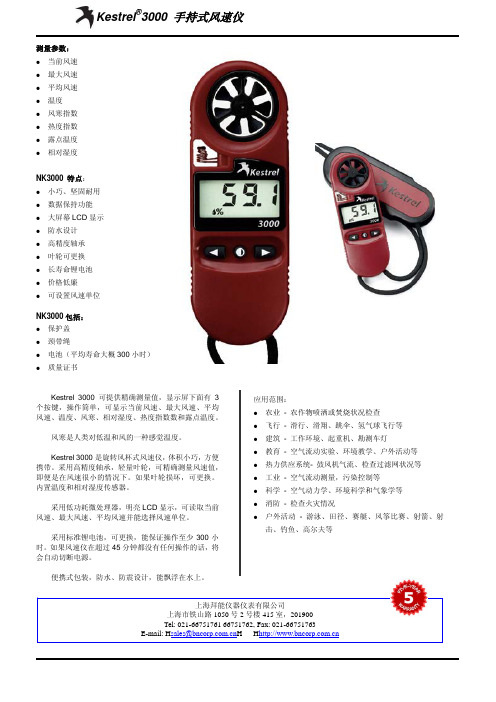
Kestrel 3000 可提供精确测量值,显示屏下面有 3 个按键,操作简单,可显示当前风速、最大风速、平均 风速、温度、风寒、相对湿度、热度指数数和露点温度。
风寒是人类对低温和风的一种感觉温度。
Kestrel 3000 是旋转风杯式风速仪,体积小巧,方便 携带。采用高精度轴承,轻量叶轮,可精确测量风速值, 即便是在风速很小的情况下。如果叶轮损坏,可更换。 内置温度和相对湿度传感器。
击、钓鱼、高尔夫等
上海拜能仪器仪表有限公司 上海市铁山路 1050 号 2 号楼 415 室,201900 Tel: 021-66751761 66751762, Fax: 021-66751763 E-mail: Hsales@H H
叶轮
温度传感器 相对湿度传感器防潮等级 震动 源自度电磁兼容性(EMC) 电池
电池寿命 自动关机
校准
保证
122mm×42mm×20mm 122mm×46mm×26mm 65g 37 0.5m 栗色 反射型 3.5 寸 LCD 9mm 1秒 当前风速 平均风速(AVG) 最大风速(MAX) 温度 风寒温度 相对湿度 热度指数 露点温度 数据保持(HOLD) Kt, m/s, km/h, mph, ft/min, Beaufort force(B) 0.4~ 60m/s(0.8~ 135mph) 0.4~ 40m/s(0.8~ 89mph) 读数的±3%或者 ±0.1m/s 小于 1% (7m/s 下操作 100 小时后) 0.1kt, m/s, km/h, mph。 -45~ +125℃ -29~ +70℃ ±1.0℃ 0.1℃ ±1℃ 0%~ 100% 5%~ 95% ±3% 0.1% ±2%(使用 24 个月后) ±2℃(温度在 21.1 和 54.4℃之间时) ±2℃(相对湿度高于 20%) 直径 25mm 高精度叶轮和轴承 用户可更换叶轮 密封、绝热、高精度 电容式高分子传感器,安装在外面的薄壁电离室
kestrel 1000手持式风速仪产品说明-NK1000便携式风速仪

全国免费热线:400-676-9335
Kestrel 1000 手持式风速仪可精确测量风速值,显示 屏下面有 3 个按键,操作简单,可显示当前风速、最大 风速和平均风速。
Kestrel 1000 是旋转风杯式风速仪,体积小巧,方便 携带。采用高精度轴承,轻量叶轮,可精确测量风速值, 即便是在风速很小的情况下。如果叶轮损坏,可更换。
校准
出厂已经校准;每一个 Kestrel 风速仪都具有一个 COC 认证证书。如需 其他认证,可与我们联系。
保证 5 年
上海瑾瑜商贸有限公司 上海市浦东新区浦东大道 2742 弄中环滨江大厦 1-1514 室 TEL:021-36320539 FAX:021-60897925 mail to:sales@
全国免费热线:400-676-9335
产品规格
物理
显示
性能 传感器 环境 其他
风速
尺寸 外壳尺寸
重量 外壳重量
颈带绳 外壳颜色 显示类型 数字高度 显示器更新
功能
风速单位 操作范围 精度范围 轴上精度 校准漂移
分辨率
122mm×42mm×20mm 122mm×46mm×26mm 65g 37 0.5m 蓝色 反射型 3.5 寸 LCD 9mm 1秒 当前风速 平均风速(AVG) 最大风速(MAX) 数据保持(HOLD) Kt, m/s, km/h, mph, ft/min, Beaufort force(B) 0.4~ 60m/s(0.8~ 135mph) 0.4~ 40m/s(0.8~ 89mph) 读数的±3%或者 ±0.1m/s 小于 1% (7m/s 下操作 100 小时后) 0.1kt, m/s, km/h, mph。
采用低功耗微处理器,明亮 LCD 显示,可读取当前 风速、最大风速、平均风速并能选择风速单位。
kestrel-4500手持式风速仪产品资料

电容式高分子传感器,安装在外面的薄壁电离室
单片硅材料气压传感器
IP67 经过落地试验,抗震性 MIL-STD-810F 操作范围:-10~ +55℃;存储温度:-30~ +60℃
CE 2 节 AAA 碱性电池,用户可更换;电池寿命平均为 400 小时。 可设置为 15 分钟或 60 分钟后自动关机 风速、温度、大气压和相对湿度出厂已经校准;每一个 Kestrel 风速仪都 具有一个 COC 认证证书 5年
当设定一个参照物时,Kestrel 4500 能够自动计算侧 风、顺风和逆风风速,如果将其和 Kestrel 风向标装置组 合,就可以在数秒内建立一个记录气象数据的小型气象 站。
Kestrel 4500 是旋转风杯式风速仪,体积小巧,方便 携带。采用高精度轴承,轻量叶轮,可精确测量风速值, 即便是在风速很小(低至 0.3m/s)的情况下。如果叶轮 损坏,可更换。
Kestrel 4500 还可根据各传感器测量数据来计算出 风寒指数、热度指数、露点温度、湿球温度和密度高度。 风寒是人类对风速和低温的一种感觉温度,风速越大, 人类感觉温度越低;热度指数是人类对温度和相对湿度
的一种:感觉温度,相对湿度越高,人类感觉温度越高;露
点温度指空气在水汽含量和气压都不改变的条件下,冷却
Kestrel®4500 手持式风速仪(可测风向)
NK4500 特点: z 多功能 z 三行图表显示 z 可存储 1400 个数据 z 最小/最大/平均风速 z 用户可定义屏幕 z 小巧、坚固耐用 z 高精度轴承 z 操作范围广 z 叶轮可更换 z 高灵敏度温度传感器 z 背光显示 z 草绿色版本采用红色背景光,可提供照明 z 可选择语言 z 采用 2 个 AAA 电池供电 z 数据可上传至电脑
maestro4000 波科参数

题目:maestro4000 波科参数一、简介maestro4000是一款先进的波科参数分析仪,具有强大的性能和多功能的特点。
该仪器广泛应用于各种领域的波科参数测试,包括电信、电力、航空航天等领域。
maestro4000采用先进的技术和算法,能够精确地分析和测试各种波科参数,为用户提供准确可靠的测试数据。
二、技术特点1.高精度:maestro4000采用先进的传感器和测量技术,能够实现高精度的波科参数测试,保证测试结果的准确性。
2.多功能:该仪器支持多种波科参数的测试和分析,包括频率响应、相位响应、损耗等参数的测试,满足用户对不同参数的测试需求。
3.快速响应:maestro4000采用快速响应的测量技术,能够在短时间内完成各种波科参数的测试,提高工作效率。
4.易操作:该仪器具有简单直观的操作界面,用户可以通过触摸屏或按钮进行操作,而无需复杂的设置和调试。
三、应用领域1.电信行业:maestro4000广泛应用于电信行业,用于测试和分析各种电信设备和通信系统的波科参数,为设备的调试和优化提供可靠的数据支持。
2.电力行业:该仪器也被广泛应用于电力行业,用于测试和分析各种电力系统和设备的波科参数,为电力系统的运行和维护提供技术支持。
3.航空航天领域:maestro4000在航空航天领域也具有重要的应用价值,用于测试和分析各种航空航天设备的波科参数,为飞行器的设计和生产提供技术支持。
四、使用方法1.设置参数:在进行波科参数测试前,用户需要根据具体的测试需求,设置相应的测试参数,如频率范围、采样率等。
2.连接设备:将待测设备与maestro4000进行连接,确保连接稳定和正确。
3.开始测试:设置好测试参数后,用户可以通过仪器的操作界面,开始对待测设备进行波科参数的测试和分析。
4.查看结果:测试完成后,用户可以通过仪器的显示屏或连接电脑查看测试结果,了解波科参数的具体数值和图形表现。
五、注意事项1.操作规范:在使用maestro4000时,用户需要严格按照操作手册的规范进行操作,避免因操作不当导致的错误结果。
n4000-13(SI)
- Fine-Line Multilayers - B ackplanes- S urface-Mount Multilayers - B GA Multilayers - M CM-Ls - CSP Attachment- W ireless Communication Infrastructure - H igh Speed Services - H igh Speed Storage Networks - I nternet Switching / Routing SystemsThe Nelco® N4000-13 series is an enhanced epoxy resin systemengineered to provide both outstanding thermal and high signal speed / low signal loss properties. N4000-13 SI ® is excellent for applications that require optimum signal integrity and precise impedance control, while maintaining high reliability through CAF2 and thermal resistance.Lead-Free Assembly Compatible- Ideally suited for assemblies with a maximum reflow temperature of 245°C1- Nelco N4000-13 has shown acceptable results in reflow conditions up to 260ºC1 depending on the PCB design and manufacturing processingTg >210ºC, outstanding thermal, electrical and signalloss properties- Excellent thickness control for tight tolerance impedance applications- Low Df and Dk allows for low signal distortion and faster signal propogation required by high frequency (1 - 10 GHz) and high reliability applications CAF 2 Resistant- The low Z-CTE and proven CAF resistance2 provide long-term reliability for both RF and digital applicationsSignal Integrity and Buried Capacitance TM Options- When used, SI glass provides enhanced electrical performance for even the most demanding applications - Approved ZBC-2000® substrate available for thinner, more reliable assemblies and increased board densities High-Tg FR-4 processing- Processes similar to traditional high Tg FR-4 materials - 90 min press at 193ºC and 275-350 psiAvailable in a variety of constructions - Vacuum laminated- Available in a wide variety of constructions, copper weights and glass styles including standard copper, double treat and RTFOIL ® laminate.- Meets UL 94V-0 and IPC-4101/29 specifications - All Nelco® materials are RoHS compliant.Global AvailabilityHigh-Speed Multifunctional Epoxy Laminate & PrepregNelco ® N4000-13Nelco ® N4000-13 SI ®Park’s UL file number: E36295ApplicationsNelco Products, Inc., California+1.714.879.4293Neltec, Inc., Arizona +1.480.967.5600Nelco Products Pte, Asia Pacific +65.6861.7117Neltec, SA, France + info@P A R KE L E C T R O C H E M I C A LC O R P .Rev 4-10Mechanical PropertiesN4000-13-13 SIU.S. Units N4000-13-13 SI MetricTest MethodPeel Strength - 1 oz. (35 micron) Cu After Solder Float7.57.5 lb / inch 1.31 1.31 N / mm IPC-TM-650.2.4.8 At Elevated Temperature8.1 8.1 lb / inch 1.42 1.42 N / mm IPC-TM-650.2.4.8.2a After Exposure to Process Solutions 9.0 9.0 lb / inch 1.58 1.58 N / mm IPC-TM-650.2.4.8X / Y CTE [-40°C to +125°C] 10 - 14 9 - 13 ppm / °C 10 - 14 9 - 13 ppm / °C IPC-TM-650.2.4.41Z Axis CTE Alpha 1 [50°C to Tg] 70 70 ppm / °C 70 70 ppm / °C IPC-TM-650.2.4.41Z Axis CTE Alpha 2 [Tg to 260°C] 280 280 ppm / °C 280 280 ppm / °C IPC-TM-650.2.4.41Z Axis Expansion [50°C to 260°C] 3.5 3.5 %3.5 3.5 %IPC-TM-650.2.4.41Young’s Modulus (X / Y) 4.2 / 3.3 2.4 / 2.3 psi x 106 28.5 / 22.4 16.5 / 15.9 GN / m 2 ASTM D3039Poisson’s Ratios (X / Y) 0.13 / 0.11 0.18 / 0.170.13 / 0.11 0.18 / 0.17ASTM D3039Thermal Conductivity 0.350 0.294 W / mK 0.350 0.294 W / mK ASTM E1461Specific Heat1.201.30J / gK1.20 1.30J / gKASTM E1461Electrical PropertiesDielectric Constant (50% resin content)@ 1 GHz (RF Impedance) 3.73.4 3.7 3.4 IPC-TM-650.2.5.5.9 @ 2.5 GHz (Split Post Cavity) 3.7 3.2 3.7 3.2 @ 10 GHz (Stripline)3.6 3.2 3.6 3.2IPC-TM-650.2.5.5.5@ 10 GHz (Split Post Cavity) 3.7 3.3 3.7 3.3Dissipation Factor (50% resin content) @ 2.5 GHz (Split Post Cavity) 0.009 0.008 0.009 0.008 @ 10 GHz (Stripline)0.009 0.008 0.009 0.008 IPC-TM-650.2.5.5.5@ 10 GHz (Split Post Cavity) 0.0080.0070.0080.007Volume Resistivity C - 96 / 35 / 90 108 108 M Ω - cm 108 108M Ω - cm IPC-TM-650.2.5.17.1 E - 24 / 125 107 108 M Ω - cm107 108 M Ω - cm IPC-TM-650.2.5.17.1Surface Resistivity C - 96 / 35 / 90 107 107 M Ω 107 107 M Ω IPC-TM-650.2.5.17.1E - 24 / 125 107 107 M Ω 107 107 M Ω IPC-TM-650.2.5.17.1Electric Strength 1200 1000 V / mil 4.7x10⁴ 3.9x10⁴ V / mm IPC-TM-650.2.5.6.2Dielectric Breakdown >50 >50 kV >50 >50 kV IPC-TM-650.2.5.6Arc Resistance123 123seconds 123 123 seconds IPC-TM-650.2.5.1Thermal PropertiesGlass Transition Temperature (Tg) DSC (°C) 210 210 °C 210 210 °C IPC-TM-650.2.4.25c TMA (°C) 200 200 °C 200 200 °C IPC-TM-650.2.4.24c DMA (°C) (Tan d Peak)240 240 °C 240 240 °C IPC-TM-650.2.4.24.3Degradation Temp (TGA) (5% wt. loss) 350 350 °C 350 350 °C IPC-TM-650.2.4.24.6Pressure Cooker-60 min then solder dip IPC-TM-650.2.6.16 @288°C until failure (max 10 min.) Pass Pass Pass Pass (modified)T260 30+ 30+ minutes 30+ 30+ minutes IPC-TM-650.2.4.24.1T28810+ 10+ minutes 10+ 10+ minutes IPC-TM-650.2.4.24.1Chemical / Physical PropertiesMoisture Absorption 0.10.1 wt. % 0.10.1 wt. % IPC-TM-650.2.6.2.1Methylene Chloride Resistance 0.7 0.7 % wt. chg. 0.7 0.7 % wt. chg. IPC-TM-650.2.3.4.3Density [50% resin content]1.911.79g / cm 31.911.79g / cm 3 Internal MethodNelco N4000-13 and N4000-13 SI ®High-Speed Multifunctional Epoxy Laminate & PrepregP A R KE L E C T R O C H E M I C A LC O R P .Park Electrochemical Corp. is a global advanced materials company which develops and manufactures high-technology digital and RF/microwave printed circuit materials and advanced composite materials. The company operates under the Nelco ®, Nelcote ® and Nova™ names. All test data provided are typical values and not intended to be specification values. For review of critical specification tolerances, please contact a Nelco representative directly. Nelco reserves the right to change these typical values as a natural process of refining our testing equipment and techniques. Nelco reserves the right to make changes without further notice to any products herein to improve reliability, function or design. Nelco does not assume any liability arising out of the application or use of any product described herein; neither does it convey any license under its patent rights nor the rights of others. This disclaimer of warranty is in lieu of all warranties whether expressed, implied or statutory, including implied warranties of merchantability or fitness for a particular purpose.Nelco ®, Neltec ®, Nelcote ®, Nova™, RTFoil ®, SI ® , LD ® and EF ® are trademarks of Park Electrochemical Corp. BC ®, ZBC-2000® and Buried Capacitance™ are Trademarks of the Sanmina-SCI Corporation.1Refer to the N4000-13 Best Practices document and Contract Manufacturing Q&A for PCB processing recommendations. Visit for more information.2CAF resistance has been established to greater than 500 hours using a specific OEM coupon design and test procedure. Visit for more information.。
卢布奇护盾空气净化器4000i产品介绍说明书
Series 4000i去除 99.9% 的小至 3 纳米的颗粒物PM2.5、过敏原和气体显示覆盖范围高达 48 平方米自动、睡眠模式和应用程序AC4556/00长久保护,持久健康让清洁健康的空气装点您的家飞利浦全新空气净化器系列 4000i 旨在通过提供高效时尚的解决方案,帮助完善您的家居设计,以减少家中的 PM2.5、有害气体和过敏原。
智能净化,持久健康智能感应智能自动净化净化效果快速有效快速净化效果高效的去除微粒性能高效去除有害气体的性能经认证防过敏随时随地检测和掌控空气质量实时空气质量反馈简单的 4 色显示环,易于监测通过您的智能手机应用程序追踪、监测和控制出色设计,用户友好经典的简约产品设计静音运行产品亮点智能感应智能感应器可检测空气中的细微变化,并自动调节风扇速,确保更出色的清洁性能。
智能自动净化提供 4 种专门设计的自动模式,可让您根据需要优化空气:一般模式、去污染原模式、去有害气体模式和去过敏原模式。
为您的家营造安全的港湾。
快速净化效果颗粒物 CADR (洁净空气量)高达 400 立方米/小时,不到 8 分钟可清洁 20 平方米房间中的空气*。
高效的去除微粒效率本空气净化器采用升级的 VitaShield 微护盾技术,可有效去除 99.97% 小至 0.003 微米的颗粒物(比 PM2.5 上限值小 800 倍),包括PM2.5、病毒、细菌、花粉、灰尘和宠物皮屑*。
确保您即使在重度污染的季节也可呼吸到健康的空气。
高效去除气体本空气净化器采用升级的 VitaShield 微护盾技术,可有效减少有害气体(如甲醛、挥发性有机化合物和异味),同时使其在空气中的含量保持在安全级别*。
活性炭纳米级微孔展开吸附表面积相当于30 个足球场大小,以 CADR 270 立方米/小时实现高效率的总挥发性有机化合物和甲醛净化*,延长使用寿命。
经认证防过敏本产品经专门设计,具有敏感的去过敏原模式,可有效检测并减少如花粉等过敏原。
侦检器材
GAMIC复合气体探测 复合气体探测
四、注意事项 1、该传感器不适用于含铅混合物、硅树脂、含氯 、该传感器不适用于含铅混合物、硅树脂、 的碳氢化合物场合, 的碳氢化合物场合,否则可能暂时停止传感器的正 常工作,应予以标定。 常工作,应予以标定。在危险地区不可更换电池与 充电。其工作温度为-20——+50℃。 充电。其工作温度为 ℃ 2、探测仪在首次使用前应进行充电,建议每个工 、探测仪在首次使用前应进行充电, 作天后对检测仪充电,充电时间2~ 小时 小时。 作天后对检测仪充电,充电时间 ~3小时。 3、探测仪在首次使用前应进行标定,建议每半年 、探测仪在首次使用前应进行标定, 标定一次。标定应使用标准浓度的气体。 标定一次。标定应使用标准浓度的气体。
11
GAMIC复合气体探测仪 复合气体探测仪
三、术语解释: 术语解释: 1、TWA:时间加权平均值,8小时内时间加权平均 、 :时间加权平均值, 小时内时间加权平均 即以各项的值乘各项时间后求和, 值(即以各项的值乘各项时间后求和,除以总时 间)。 2、STEL:短期暴露限制值,15分钟内的时间加权 、 :短期暴露限制值, 分钟内的时间加权 平均值。 平均值。 3、MAX:自开机始所遇到的最高气体暴露值。 、 :自开机始所遇到的最高气体暴露值。 4、LEL:爆炸极限下限值。 、 :爆炸极限下限值。
5
Kestrel 4000风速 气象测定仪 风速/气象测定仪 风速
三、操作使用: 操作使用: 5、数据查看: 、数据查看: 5.1 开机后仪器会自动检测出环境气象数据,其功能项有: 开机后仪器会自动检测出环境气象数据,其功能项有: 风速、温度、风冷、湿度、热指数、露点、气压、海拔、 风速、温度、风冷、湿度、热指数、露点、气压、海拔、密 度高度和湿球温度等10种 每种数据又可以通过3种方式来 度高度和湿球温度等 种。每种数据又可以通过 种方式来 查看(即时数据、最大/最小 平均值、 最小/平均值 图表)。 查看(即时数据、最大 最小 平均值、Chart图表)。 图表 5.2 查看单屏信息:按▼或▲翻页可实现连续循环单屏显示 查看单屏信息: 信息。假如开机时显示是时间, 则显示顺序如下: 信息。假如开机时显示是时间,按▼则显示顺序如下:时间 →风速 温度 风冷 湿度 热指数 露点 湿球湿度 气 风速→温度 风冷→湿度 热指数→露点 湿球湿度→气 风速 温度→风冷 湿度→热指数 露点→湿球湿度 海拔高度→密度高度 综合信息1→综合信息 综合信息2→综合信 压→海拔高度 密度高度 综合信息 海拔高度 密度高度→综合信息 综合信息 综合信 时间。 息3→时间。 时间 5.3 在即时数据界面下(时间除外),如果要查看最大 最小 在即时数据界面下(时间除外) 如果要查看最大 最小/ 如果要查看最大/最小 平均值、 图表, 键即可。 平均值、Chart图表,按 ► 或 ◄ 键即可。没有数据时则显 图表 示――。 。
4000系列数字便携式分析仪使用说明书
Instruction Manual 4000 Series Digital Portable AnalyzerService Department(800) 458-6153 ext. 121(818) 882-2331 ext. 121FAX(818)341-0642E-mail:************************THIS P AGE INTENTIONALL Y LEFT BLANKTABLE OF CONTENTSSECTION TITLE PAGE1.0 Equipment DescriptionFront Panel 4Rear Panel 6Right Side Panel 7Internal components 8 2.0 Operating InstructionsSetting the Alarm 9Zeroing the Instrument 10Sampling 11 3.0 CalibrationIntroduction 12Sample Bag & Pressurized Cylinder Calibration 14Calibration Procedure 15 4.0 General MaintenanceBattery Life 16Battery Charging & Replacement 16Water loss in Refillable Sensors 18Long Term Storage 23Post Storage Startup 235.0 Troubleshooting 246.0 Warranty 257.0 Return Authorization 268.0 AppendixINTERFERING GAS DATA 27SCRUBBER INFORMATION 31Note:It is not necessary to calibrate the monitor whenreceived from the Interscan or an authorized distributor.All Interscan monitors are calibrated at the factory prior toshipment.The Interscan 4000 Digital series operates on the principle of pullinga sample (Sample draw) through a sensor. The Electrochemicalsensor is manufactured by Interscan. Electrochemical means thatit produces an electrical current proportional to the level of gaspassing through. The large size of the Interscan sensors results inlarger reactive surface area which yields greater sensitivity. Equipment Description(fig. 1)Designation FunctionLCD Display:Indicates gas level when function switch is inZERO, SAMPLE INACTIVE or SAMPLEACTIVE, and battery level when on BAT.TEST A or B.ALARM Light:LED. Flashes ON/OFF when alarm setpoint is exceeded.ALARM SET:25-Turn potentiometer with a screwdriveradjustment. Sets the alarm trip point at thedesired gas level. (low alarm set must begreater than 5% of the full scale).SPAN/CAL:25-Turn potentiometer with a screwdriveradjustment. Sets display to correspond to theconcentration of the calibration gas used forcalibrating the instrument or to the levelspecified on ECS certificate.FUNCTION SWITCH:Rotary switch as follows:OFF:Analyzer power is OFF.SAMPLEINACTIVE:Analyzer power is ON (pump is OFF),Sampling is inactive.SAMPLEACTIVE:Analyzer power and pump are on. Also in thisposition the analyzer is zeroed. Samplemeasurements and calibration areaccomplished in the sample mode.BAT.TEST A:Indicates state of charge of the Nickel-Cadmium (NiCd) batteries on the LCDDisplay. These batteries power the pump &alarm. Recharge if the LCD Display level fallsto or below 100 (ignore decimal point).BAT. TEST B:Indicates state of charge of the “C” sizealkaline batteries on the LCD Display. Thesebatteries power the main circuitry, display andare NOT re-chargeable. Replace if the LCDDisplay level falls to or below 100 (ignoredecimal point). You must allow an overnightstabilize prior to use if the batteries arereplaced. Batteries are to be checkedevery 30 days.ZERO:10-Turn Potentiometer. Allows the meter to beadjusted to zero, by compensating for anybackground signal.(fig. 2)Designation FunctionINLET:¼” O.D. Quick connect or compression gasfitting.OUTLET:¼” O.D. Quick connect or compression gasfitting.RECORDER OUTPUT:¼” phone jack for Analog recorder outputconnection. Typically 0-100mV. Tip –positive, Ring – ground.CHARGER INPUT: 3.5mm phone jack for 9V DC, 100mA chargerinput. Tip – positive, Ring – ground.SENSOR SCREWS:Used to hold Sensor or Sensor base in place.(fig. 3)AUDIBLE ALARM:Piezoelectric Horn, sounds when alarm setpoint is exceeded.The above (fig 3) page 7, #12 indicates two #1 Phillips-head screws located on the right side panel. Removing these screws allows access to the internal components. Do not remove any other screws(fig. 4)Operating InstructionsNormally, the alarm is set at the Factory at 50% of full scale. Thealarm can be reset to any desired level by following the procedurebelow. Minimum alarm level must be greater than 5% of the fullscale measuring range.Set FUNCTION switch to SAMPLE INACTIVE. Using the ZEROcontrol, advance the LCD display to the desired alarm set point.Some analyzers require the use of span tool (provided). Adjust theALARM SET (fig. 1 pg. 4)control until the alarm sounds. Adjust theZERO control slightly counterclockwise until the alarm is silent. Toconfirm setting slowly adjust the ZERO control clockwise until thealarm sounds. Re-adjust the ALARM SET control if necessary.Adjust the ZERO control for a reading of “0” on the display.The Analyzer must always be zeroed, prior to use.Zero adjustments must be made in the SAMPLE ACTIVE mode,i.e. with the pump on, in air free of interfering gases. If necessary,use zero air or a C-12 filter (provided) to zero in the sampling area.When using C-12 zero filter, connect externally to gas inlet. Allowreading to stabilize, before making final zero adjustment,(stabilization can take approximately 20 minutes). The C-12 filtermust be removed after zeroing the analyzer.Analyzer must be zeroed prior to sampling (section 2.1).Set the FUNCTION switch to SAMPLE ACTIVE to activate the pump. If the INLET or OUTLET is blocked, the pump may stall. Note: Running the Analyzer with blocked INLET or OUTLET may lead to the sensor leaking caustic electrolyte leading toanalyzer damage.Power analyzer off, and clear the blockage. To reset the pump, set the FUNCTION switch to SAMPLE INACTIVE momentarily and then switch again to SAMPLE ACTIVE.Nominal sample rate in MOST analyzers is approximately 1.0, ±0.2 liter per minute. NOTE: For hydrazine analyzers with the measuring range of 0-100ppb the sample flow rate is 2.2 ± 0.2 liters per minute.The Average sample run time, starting with fully charged “C” NiCd batteries, is 12 hours. If the BATTERY TEST “A” indication is down to 100 on the LCD display, the flow rate may have started to decrease. This is usually not a problem unless very precise readings are required.Sampling from high pressure may only be achieved by using the method indicated in (fig. 5).Note: The sample to the Interscan Analyzer must be drawn perpendicular to the Sample flow stream.(fig. 5)CalibrationAll analyzers are factory calibrated prior to shipment.There is no easy answer as to how often a monitor should becalibrated. This is strictly a function of the application (gasconcentration and frequency of exposure to target gas). Thepurpose for calibration is to compensate for any possible decreasein sensor sensitivity. The primary cause of sensitivity decrease isexcessive loss of water by evaporation. A secondary cause maybe by contamination from unknown sources. H2S sensors show anadditional decrease in sensitivity due to internal sulfur formation, therate of which depends on the gas concentration.Interscan’s SENSOR EXPRESS® program streamlines downtimeby sending you a pre-calibrated sensors on a regular basis per yourneeds, without the burden of returning sensors to our factory for re-certification. The sensors are shipped to you either twice , threetimes, or four times per year at your discretion.Follow the instructions received with the Sensor, allow to stabilize,and the instrument is ready for use. The factory recommendedprocedure for calibrating all INTERSCAN analyzers, involves theuse of certified calibration gas or a permeation device. Besidesbeing essential for calibration, having a known certified gasstandard on hand allows the user to test the analyzer at any time todetermine that it “really works”As indicated on the certification sheet, the Sensor Express®. It doesnot certify the analyzer as a whole. Most importantly, the SensorExpress® program is not a substitute for basic analyzermaintenance, nor does it check for malfunction of the analyzercomponents.Whatever the source of calibration gas, the recommended method is to collect the gas in the proper sample bag, which is then attached to the analyzer INLET. The calibration gas is drawn from the proper sample bag through the sensor. An exception to the use of a sample bag is for those gases, which are reactive with, or chemisorbed by the bag itself (e.g. Chlorine, Hydrazine). Teflon® or Tedlar® bags are suitable for H2S, SO2, NO and NO2. Several bag materials are suitable for CO. Contact the Factory for recommendations.The sample bag method is the factory-recommended method for calibration. Since an internal pump is used, the same flow rate conditions during the sample and the calibrate modes are assured, eliminating errors due to flow rate differences. For most applications, using a bag is the simplest procedure.A regulated pressurized certified cylinder fitted with a tee-manifold (fig. 6) and unrestricted vent is a good procedure in place of the sample bag, as long as the flow rate of the gas is at least 140 percent that of the sample pump.(fig. 6)Analyzer must be zeroed prior to calibration (sec 2.1).1. For all gases, except Chlorine or other chemisorbable types, fill the 5 litersample bag with calibration gas, and attach it to the external inlet fitting.This is best done by attaching a short length 4 inch (101.6mm) of 1/4 inch(6.35 mm) O.D. Teflon tubing to the sample bag, then inserting into theinlet fitting.2. Set the FUNCTION switch to SAMPLE ACTIVE.3. Allow 2 to 3 minutes for the reading to stabilize, and by using theSPAN/CAL control, set the display to match the calibration gas concentration being used.4. Remove the sample bag from the analyzer and allow the display tostabilize.5. The analyzer is now calibrated and set up for operation.NOTE: If you require additional information on Calibrationprocedures, please contact the Service Department at 1-800-458-******************************************General MaintenanceBecause of current requirements of the circuitry, “C” size alkalinebattery life should be check on a monthly basis, whether the unit isoperating or not. Note: Batteries vary in capacity bymanufacturer and may provide more battery life. Analyzermalfunction, as a result of low battery, will be evident as eitherinability to zero the monitor or clipping of the display at a fixedreading below full scale.Nickel-cadmium battery life is indeterminate. It is somewhatdependent upon how well the charge level is maintained.All models of the 4000 Series analyzers use two “C” size alkalinebatteries. These are located on the hinged door, right side (fig. 4 pg.8). Polarity is marked on the door over the battery holder.A few minutes warm-up/stabilization is needed before using theanalyzer if alkaline batteries are replaced before Battery Test “B”indicates a low battery condition (100). Replace “C” alkalinebatteries and allow monitor to stabilize overnight if the batteries arelow or dead. The FUNCTION switch should be set to OFF duringthis time. This is performed to allow the sensor time to stabilize.The rechargeable batteries are ½ “C” size NiCd and are rated at0.80 ampere hours. They are mounted on the hinged door, left side(fig. 4 pg. 8). Polarity is marked on the door, over the battery holder.All models use four ½ cell “C” size NiCd batteries. Condition isshown in the BATTERY TEST “A”, FUNCTION switch position. TheNiCd battery voltage changes quite rapidly as it approaches therecharge point, which makes accurate display indication difficult. Itis recommended that the batteries be recharged if the reading inBATTERY TEST “A” is at 100 (ignoring the decimal place). Allowingthe reading to drop below 100 is not recommended. Note: NiCd batteries can develop cell memory. Cell memory is caused by running the analyzer on battery power for a short period of time REPEATEDLY i.e: Running the analyzer for 20 minutes and then recharge. If this occurs repeatedly, the NiCd battery life will only retain a 20 minute charge memory.The charger is an external 9V DC, 500mA transformer and is connected to the rear of the unit prior to charging. The tip is positive and the ring ground. The FUNCTION switch should be set to OFF or SAMPLE INACTIVE when charging. The recommended charge time is 16 hours.(fig. 7)All sensors provided with a fill port require that the electrolyte matrix is maintained in a near-saturated condition in order to provide optimum performance. This is achieved by injecting distilled or deionized water into the sensor via the red plug, using the plastic syringe (provided).Refer to (fig. 7 pg. 16). Refillable sensors are identified by the red fill plug in the side of the sensor. The fill plug location may vary from(fig. 7 pg. 16). There are two types of refillable sensors. The S-type is a shorter sensor of slightly over 2 1/2 inches ( 64 mm) in height; the P-type is almost 4 inches (104 mm) in height. “P” and “S” type sensors connect to the analyzer by different connection methods.For portable survey monitors, the sensor should be removed and weighed every 1 to 2 months, depending upon usage. The weight loss is indicated on the weight label on the side of the sensor. Sensor weight is restored be removing the sensor from the analyzer and comparing the current weight of the sensor with its original weight (in grams). Sensor weight is indicated on a label located on the side of the sensor.There are three types of gas fittings used depending on the age of the original sensor and the gas being measured.(fig. 8)Male elbow ¼ O.D. tube compression fittingThis is a compression fitting comprised of the body, nut and two ferrules (fig. 8). Disconnect by loosening the nut until the tubing can be pulled away from the body. To re-attach insert the tubing and tighten the nut. Do NOT over tighten the nut as this will damage the nut and fitting(fig. 9)Quick connect male elbowThis is a quick connect system comprised of the body, o-ring and ferrule (fig. 9). Disconnect by pushing on the ring where the tubing enters the fitting and gently pulling on the tubing. Re-attach by inserting the tubing all the way in and then gently pull backward.(fig. 10)Barbed male elbowThe fitting uses a barbed connector system (fig. 10). Disconnect by pulling on the tubing. Re-attach by pushing the tubing onto the fitting until firmly seated.Fig. 11For P-type sensors refer to (fig. 11). Disconnect the 2 electrical connections to the sensor. Disconnect the tubing from each gas fitting. Loosen the screw indicated as “A”. Loosen the clamp screw “B” until the sensor can be removed from clamp.NOTE: DO NOT REMOVE ANYTHING ELSERestore the sensor to within 5 grams original sensor weight by injecting an equivalent cc of distilled or deionized water (10g. weight loss means add 10cc water). DO NOT OVERFILL. If sensor will not take on any more liquid (liquid starts coming out the fill port) do not attempt to add additional distilled water.Note: Weight loss in excess per sensor weight label may prevent the restoration of the weight to within 5 grams of the original weight.DO NOT OVERFILL. After weighing and refilling replace the sensor in the analyzer, tighten screw “B” taking care only to make it tight so as to secure the sensor. Then tighten screw “A”, do not over tighten.Assure that all electrical and pneumatic fittings are secure. The sensor should be allowed to stabilize forseveral hours with power off.(fig. 12)For S-type sensors refer to (fig. 12). Disconnect the two electrical connections to the sensor. Disconnect the tubing from each gas fitting. Remove the two Sensor Screws (# 7).NOTE: DO NOT REMOVE ANYTHING ELSE!!Restore the sensor to within 5 grams original sensor weight by injecting an equivalent cc of distilled or deionized water (10g. weight loss means add 10cc water). DO NOT OVERFILL. If sensor will not take on any more liquid (liquid starts coming out the fill port) do notattempt to add additional distilled water.Note: Weight loss in excess per sensor weight label may prevent the restoration of the weight to within 5 grams of the original weight.DO NOT OVERFILL. After weighing and refilling replace the sensor in the analyzer, tighten screws on the rear of the analyzer. Assure that all electrical and pneumatic fittings are secure. The sensor should be allowed to stabilize for several hours with power off.Turn FUNCTION swit ch to “OFF” position. Disconnect charger from analyzer. Detach 15 pin “D” connector from circuit board. Remove alkaline batteries and cover analyzer to protect from dust.24 Hours Before Using:Uncover the analyzer. Install FRESH alkaline batteries. Reconnect 15-pin “D” connector from circuit board. Connect the charger to the analyzer to charge NiCd batteries.After 24 Hours:Follow instructions in Section 2.0. Analyzer is ready to use or calibrate.WarrantyINTERSCAN CORPORATION warrants portable analyzers of itsmanufacture (sensors, batteries, fuses, lamps, tubing, fittings,filters, and scrubbers excepted) to be free from defects in materialand workmanship for a period of one year from date of shipment.INTERSCAN CORPORATION warrants sensors of its manufactureto be free from defects in material and workmanship for a period ofsix months from date of shipment.INTERSCAN CORPORATION'S sole obligation under thiswarranty is limited to repairing or replacing, at its option, any itemcovered under this warranty, when such item is returned intact,prepaid to the factory (or designated service center).This warranty does not apply to any of our products which havebeen repaired or altered by unauthorized persons, or which havebeen subject to misuse, negligence, or accident, incorrect wiring byothers, installation or use not in accordance with instructionsfurnished by the manufacturer, or which have had the serialnumbers altered, effaced or removed. The sensors are factorysealed and must not be opened or modified in the field for thewarranty to remain in effect. This warranty is in lieu of all otherwarranties, whether expressed or implied.Additionally, in a custom system, warranty on any component shallnot exceed the manufacturer's warranty given to INTERSCANCORPORATION.Return AuthorizationAll returns for repairs require a "RETURN AUTHORIZATIONNUMBER" issued by the INTERSCAN Service Department uponrequest. Below is the link to the RMA form:/contact/index.phpThis is done primarily to cause the user to contact the factorydirectly. The reason for this is that a high percentage of serviceproblems are resolved over the telephone, avoiding the need forreturning the analyzer or part.Should return of the analyzer or part be advised by the ServiceDepartment, the "RETURN AUTHORIZATION NUMBER" willexpedite prompt return of the repaired unit.For service information, please contact:INTERSCAN CORPORATIONService Department(800) 458-6153 ext. 121(818) 882-2331 ext. 121FAX(818)341-0642E-mail:************************Appendix AINTERFERING GAS DATANo analytical method is completely specific. Gases present in the environment, other than the "target" gas of measurement, may affect analyzer response. Interferences are not necessarily linear, and may also exhibit time dependent characteristics.The charts that follow detail the approximate concentration in parts per million of interfering gas required to cause a 1 ppm deflection in the chosen analyzer. In many cases, specificity can be improved. Please note that the response values given are not absolute, and may vary depending on sensor formulation.The special case of how alcohols affect electrochemical sensors is discussed in this Knowledge Base article. ()For further information on the effects of interfering gases, please contact the factory.The charts follow the format, and grouping of gases, that was originally established in early Interscan print brochures.Chart 1: CO, Cl2, ClO2, H2, H2S, NO, NO2, O3, SO2 analyzersChart 2: Ethylene oxide (EtO) (C2H4O) analyzersChart 3: Formaldehyde (HCHO) analyzersChart 4: HCl, HCN, hydrazine analyzersChart 5: C2H4 (ethylene) analyzers(1) Data shown for H 2S models with ranges higher than 0-1999 ppb (2) Data shown for H 2S models with ranges of 0-1999 ppb and lower‡ = Hydrocarbons¤ = Rejection ratio can be improved electronically¶ Isopropyl alcohol represents the most significant interference on the ethylene oxide sensor, but in nearly all cases, potential problems can be overcome. Typical remedial actions include:a. Point shutdown/automatic restart, which allows the operator to temporarily interrupt monitoring at points that could be affected when isopropyl alcohol is used. Monitoring restarts automatically on a time-adjustable basis.b. Selection of monitoring points away from those areas that may be unduly affected by isopropyl alcohol.c. Using alternative germicides, which do not contain isopropyl alcohol.The EtO sensor may also respond to strong odors of colognes and perfumes, and to certain floor strippers and waxes. Refer to guidelines above covering isopropyl alcohol. Remember that you are attempting to monitor parts per million levels of ethylene oxide in an environment that may contain percent (10,000 ppm = 1 percent) levels of these potentially interfering compounds.= Negative interference= Negative interference § = Scrubber available= Negative interference= Negative interferenceAppendix B SCRUBBER INFORMATION。
- 1、下载文档前请自行甄别文档内容的完整性,平台不提供额外的编辑、内容补充、找答案等附加服务。
- 2、"仅部分预览"的文档,不可在线预览部分如存在完整性等问题,可反馈申请退款(可完整预览的文档不适用该条件!)。
- 3、如文档侵犯您的权益,请联系客服反馈,我们会尽快为您处理(人工客服工作时间:9:00-18:30)。
采用高精度轴承,轻量叶轮,即便是在风速很小(低 至 0.3m/s)的情况下也可精确测量风速值(±3%)。如果叶
可采用 2 节 AAA 电池来供电,可更换,具有 2 种省电 模式来延长电池寿命。可选语言:英语、法语、意大利语、 西班牙语和德语。
上海瑾瑜商贸有限公司 上海市浦东新区浦东大道 2742 弄中环滨江大厦 1-1514 室 TEL:021-36320539 FAX:021-60897925 mail to:sales@
对于建筑工人、工程师、船员、飞行员、农民或热 爱户外活动的人,只需一个仪器,就能得到全面的气象 数据。对于夜晚黑暗使用环境,NK4000 草绿色版本还特 别增加设计了红色背景光,可提供照明。
每一个参数都可以三种格式显示:当前值、最小/最 大/平均值、图表。风速仪屏幕可以设置成同时显示三个 常用的参数。
0%~ 100%
5%~ 95%
±3%
0.1% ±2%(使用 24 个月后) 10~ 1100mBar(25℃) 750~ 1100mBar(25℃)
±1.5mBar
0.1mBar 典型 每年±1mBar
-2000~ +9000m
-2000~ +6000m
±15m
1m ±75m(温度在 0 和 37.8℃之间时) 直径 25mm,高精度叶轮和轴承,用户可更换叶轮 密封、绝热、高精度 电容式高分子传感器,安装在外面的薄壁电离室 单片硅材料气压传感器
轮损害,可以进行更换。 采用外置温度传感器,反应速度快,测量精度达到
±1℃,分辨率为 0.1℃。采用特殊保护壳保护温湿度传感器 以免污染,使温湿度的测量精度保持在±3%。
单片硅材料气压传感器可精确计算大气压和海拔数 据,精度分别为 0.1mBar 和 1m。
Kestrel 4000 还可根据各传感器测量数据来计算出风 寒指数、热度指数、露点温度和密度高度。风寒是人类对 风速和低温的一种感觉温度,风速越大,人类感觉温度越 低;热度指数是人类对温度和相对湿度的一种感觉温度, 相对湿度越高,人类感觉温度越高;露点温度指空气在水 汽含量和气压都不改变的条件下,冷却到饱和时的温度; 密度高度是将气压高度值对温度校验后的高度。
NK4000 可测量参数: z 风速 z 温度 z 风寒 z 相对湿度 z 热度指数 z 露点温度 z 湿球温度 z 大气压 z 海拔高度 z 密度高度 z 时间/日期
Kestrel 4000 可让您随时随地都能取得精确气象数 据,只需几个按键,就能得到如下数据:当前风速、最 大风速、平均风速、温度、风寒、相对湿度、热度指数、 露点温度、湿球温度、大气压和海拔高度、密度高度。
Kestrel®4000 手持式风速仪
露点温度精度
热度指数精度
湿球温度精度
操作范围
精度范围
相对湿度
精度
分辨率
校准偏移
操作范围
精度范围
大气压
精度
分辨率
校准偏移
操作范围
精度范围
海拔高度
精度
分辨率
密度高度精度
叶轮
温度传感器
相对湿度传感器
大气压传感器防潮等级震动温度电磁兼容性(EMC)
电池
自动关机
校准
保证
127mm×45mm×28mm
102g 0.2m 和 0.5m 灰色、草绿色和黄色 点矩阵 LCD,场致(EL)发光背光 1秒 2 秒到 12 小时之间,可调;图表可显示 2000 个数据点;可手动或自动采 集数据,数据可上传至电脑。 风速(当前值、最大/最小值、平均值) 温度 风寒 相对湿度 热度指数 露点温度 大气压 海拔高度 密度高度 湿球温度
Kestrel®4000 手持式风速仪
全国免费热线:400-676-9335
NK4000 特点: z 多功能 z 三行图表显示 z 可存储 2000 个数据 z 最小/最大/平均风速 z 用户可定义屏幕 z 小巧、坚固耐用 z 高精度轴承 z 操作范围广 z 叶轮可更换 z 高灵敏度温度传感器 z 背光显示 z 草绿色版本采用红色背景光,可提供照明 z 可选择语言 z 采用 2 个 AAA 电池供电 z 数据可上传至电脑 z 有灰色、草绿色和黄色版本
IP67 经过落地试验,抗震性 MIL-STD-810F 操作范围:-10~ +55℃;存储温度:-30~ +60℃
CE 2 节 AAA 碱性电池,用户可更换;电池寿命平均为 400 小时。 可设置为 15 分钟或 60 分钟后自动关机 风速、温度、大气压和相对湿度出厂已经校准;每一个 Kestrel 风速仪都 具有一个 COC 认证证书 5年
Kt, m/s, km/h, mph, ft/min, Beaufort force(B) ℃, ℉
mBar, inHg, hPa, psi
m, ft
dd/mm/yy, mm/dd/yy, 12 hour, 24 hour 0.4~ 60m/s(0.8~ 135mph) 0.4~ 40m/s(0.8~ 89mph) 读数的±3%或者 ±0.1m/s 小于 1% (7m/s 下操作 100 小时后) 0.1kt, m/s, km/h, mph。 -45~ +125℃ -29~ +70℃ ±1.0℃ 0.1℃ ±1℃ ±2℃(相对湿度大于 20%时) ±2℃(温度在 21.1 和 54.4℃之间时) ±2℃(温度在 0 和 37.8℃之间时)
产品规格
物理 显示
性能
传感器 环境 其他
Kestrel®4000 手持式风速仪
全国免费热线:400-676-9335
尺寸 重量 颈带绳 外壳颜色 显示类型 显示器更新
数据采集
可测量参数
风速单位
温度单位
气压单位
海拔单位
时间和日期显示
操作范围
精度范围
风速
精度
校准漂移
分辨率
操作范围
精度范围
精度
温度
分辨率 风寒精度