光子云模具监视器简介
新版江苏省苏州机器视觉工商企业公司商家名录名单联系方式大全44家
阊区 苏州市阊胥路 RFID系统,工业传感器光电开关
283号7101
等,工业安全系统,工业控制系
统,机器视觉
光子云光电有限公 司
江苏
苏州市吴江荃泰机 器视觉系统有限公 江苏 司
苏州 苏州
江苏 昆山市 萧林东 路3500
模具监视器,模具保护器,注塑 机模具防护,机器视觉检测,防 呆保护
吴江经济开发区云梨 连接器视觉检测设备,AOI检测
江兴东路1128号 亿 机,步进电机,光栅尺,运动控
仕登工业园1号楼4 制器,数控系统,机器人,机器
楼
视觉等高科技产品
蓬青路888号立德企 富士康模具保护器,机器视觉系
业家园1栋1室
统,模具监视器
江苏省苏州市昆山市 巴城镇清华科技园
计算机机器视觉产品开发及销售
江苏 新沂市 苏州吴
中区珠江南路368号 木渎科技创业园
机器视觉光源,非标自动化设备
2210
昆山英赛特自动化 科技有限公司
江苏
苏州
江苏省昆山市玉杨路 777号中节能产业园 67栋
机器视觉系统与工业自动化设备 的开发,集成,制造
蓝筹图像处理科技 (苏州)有限公司
江苏
苏州
新南中路567号
智能机器视觉软件
渡莱迪克精密电子 (苏州)有限公司
江苏
苏州
键盘检测器,按键外观检测器,
江苏 苏州市 苏州新 AOI检测器,功能检测器,键盘
区竹园路9-1号狮山 AOI,外观检测器,机器视觉系
工业园6幢
统,视觉检测解决方案,电气治
具,CCD检测仪
苏州德创测控科技 有限公司
江苏
苏州
金枫南路1258号(金 桥汽配产业园)B3幢 5楼
7 3D LUT触摸监视器 2200nits阳光可见 使用说明书
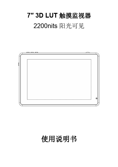
7″3D LUT触摸监视器2200nits阳光可见使用说明书产品简介:欢迎使用本公司生产的7寸高亮触摸摄影监视器。
本监视器配备SDI(可选)、HDMI输入和输出,辅助电源输出,触摸屏菜单操作、HDR监看及支持用户3D LUT上载等特征。
高级特性包括波形图、矢量图、直方图、音频柱、辅助对焦、伪色彩、斑马纹、点对点、中心标记、安全标记、遮幅标记、单色显示、图像静止、放大、变形模式等,是一款理想的便携式轻量级的取景配套监视器。
监视器还配备有电池扣板,可通过外置电池或者通过电源适配器由市电进行供电。
使用产品前,为达到最佳使用效果,请阅读本说明书注意事项1.移动机子时慎防跌落导致机器严重损坏或损毁2.此产品中的液晶屏由玻璃制成,如屏破损可能会造成其他伤害。
3.保持产品远离热源,避免机器长时间暴露在阳光下,这将导致液晶屏的损坏。
4.不要用化学试剂或溶剂擦洗机子,请用软布擦除机子上的尘污,以保证本机的亮丽。
5.机内无用户可调组件,非专业人员请勿自行打开本机或自行尝试修理本产品,以免造成不必要的损坏。
产品特点触摸屏菜单操作支持HDR监看3D LUT Log灰片转换Rec.709,支持用户3D LUT上载1920x1200全高清IPS屏2200nits阳光可见,光感应亮度自动调节全波形显示、波形图、矢量图、RGB直方图亮度直方图,检验图片亮度的一种量化工具,指导摄影曝光掌握 辅助对焦(可选择黄、红、绿、蓝、白对焦边缘)斑马纹及伪色彩辅助功能,方便指导拍摄时用光和后期制作单色显示(灰、红、绿、蓝)图像放大功能变形模式图像横向和纵向翻转图像静止点对点显示中心标记、安全标记及遮幅标记图像亮度、对比度、锐度、色相、饱和度及色温调整耳机立体声输出方便监听支持DC8.4V电源输出给单反或微单相机供电目录一.产品描述--------------------------------------------------41.按键说明--------------------------------------------------42.接口说明--------------------------------------------------53.供电方式--------------------------------------------------64.安装方式--------------------------------------------------7二.菜单操作说明--------------------------------------------8三.菜单功能说明--------------------------------------------9四.信号支持格式-------------------------------------------13五.技术参数-------------------------------------------------14六.常见故障排除-------------------------------------------15一.产品描述1.按键说明①.指示灯:正确接入电源后指示灯亮(红色),长按左侧键开机,指示灯转为黄色,接入信号后,指示灯转为绿色。
北醒光子科技TFmini Plus小型激光雷达模组产品规格书说明书

TFmini Plus小型激光雷达模组1. 产品描述TFmini Plus是一款小型化激光雷达模组,基于ToF(飞行时间)原理,主要用于实现稳定、精准、高频的距离测量功能。
主要产品特点:⚫高帧率(最高可达1000Hz)⚫小体积⚫低功耗(550mW,低功耗模式小于100mW)⚫IP65防护主要应用场景:⚫行人检测⚫车辆检测⚫高度计⚫机器人防跌落2. 技术规格参数表1 TFmini Plus规格参数表②输出帧率默认值为100Hz,支持自定义配置,可配置值为1000/n (n为正整数)③更详细重复精度说明见产品说明书④该角度为理论值,实际角度值存在一定偏差3. 产品外观尺寸图图1 TFmini Plus外观尺寸图(单位:mm)4. 通信接口TFmini Plus包含两个版本,UART及I2C,接口说明如下:表 2 数据通信接口说明——UART表 3 数据通信接口说明——I2CSJ-PM-TFmini Plus-01 A07 产品规格书北醒(北京)光子科技有限公司5.表 4 可配置参数列表6. 产品认证标准TFmini Plus使用说明书激光雷达模组所述产品产品型号:TFmini Plus产品名称:TFmini Plus激光雷达模组制造商公司:北醒(北京)光子科技有限公司地址:中国北京海淀区信息路28号版权声明本文档受版权保护。
其中涉及到的一切权利归北醒公司所有。
只允许在版权法的范围内复制本文档的全部或部分内容。
未经北醒公司的官方书面许可,不允许对文档进行修改、删减或翻译。
© 北醒公司版权所有产品认证前言尊敬的用户:您好。
感谢您选择北醒光子科技的产品,我们很荣幸参与您解决问题的过程。
为了让产品的使用体验更好,我们特此制定产品使用说明书,帮助您更加便捷的使用产品,从而更好的帮您解决问题。
本说明书中已涵盖常见情况下的使用说明及问题处理措施,但仍不能保证可完全解决您的问题。
如果您在使用产品的过程中遇到其他问题,欢迎您咨询我们的技术支持人员(********************),我们竭诚为您解决产品使用中的任何问题。
模具监视保护器的工作原理

模具监视保护器的工作原理
模具监视器(又称模具监控器,模具保护器,模具电子眼)主要应用在注塑与压铸生产行业,是利用图像对比的原理来起到监视与保护模具的作用。
简单的说,模具监视器就是一台工业电脑加上一台工业相机,拍了OK的图片保存在电脑里面,生产过程中,每次都在固定的时间在拍图片与电脑里面保存的图像比较一下,看一下实时图片是否与基电脑里保存的准图片有差别,图像差别大过设定的参数就会报警。
模具监视器一般保存2张基准照片,第一次是开模后,顶出前,保存一张OK有产品的照片,生产过程中每次都在顶出前进行一次对比,检测产品是否缺胶,少做,批锋,或者粘前模;发现有不同,就会停止顶出,并且报警。
第二次是顶出后,合模前,保存一张模具表面干净可以合模的图片,以后每次都在合模前检测产品/水口是否掉落,顶针/斜顶/行位是否到位,镶件等是否安装到位等等;发现有不同,就会停止合模,并且报警。
由此可见,模具监视保护器就像一个人工智能电子眼在注塑机旁边实时监视生产产品质量和保护模具。
(以上为深圳市立恒视觉技术有限公司原创文章,未经允许,不得转载)。
模具监视器

◆连接器表面缺陷检测 (废边、缺料、熔接 痕等)
◆连接器共面平整检测 ◆ Marker拒收标签检测 ◆料带针脚间距检测
自动放 料系统
料带Pin脚 及电镀检测
料带定 位系统
全自动生产 包装检测
料带模具 内定为检测
自动剪切 包装系统
注塑件拒 收标签检测
注塑件尺寸 及表面检测
单料带插件成型检测
双料带插件成型检测
检 测 速 度 : 双 料 带 秒 内 可 以 检 测 个
检 测 精 度 : 0.02mm
检 测 面 积 大 约
眼检 堵测 塞指 等标 缺: 陷缺 料 、 飞 边 、 PIN 的 间 距 、 鱼
40mm*35mm
12 8
废 边 N G
缺 料 N G
Pi n 脚 间 距 N G
特殊视觉检测篇
汽车部件检测应用 产品:汽车部件 检测类型:插件定为检测 注塑机:DEMAG立式注塑 穴数:2Cav *2 检测精度:+0.05mm
☞ 多路CCD输入功能 ☞ 手持一体式设计 操作便捷 ☞ 现场多结构安装方式
☞ 智能自动设定监测区域 ☞ 一次、一键设定功能 ☞ 人机对话界面设定
连接器在线QC检测
为您节省人工成本,进而100%的无误,您还不赶快联系我们吗?
连接器插件注塑成型在线检测
In-Line Vision System
◆金属料带电镀层及涂 层缺 陷检测
按键组装检测应用
OK 产品:汽车Video部件
NG
检测类型:按键装配漏装、错装、镭射不良
OQC扫描检测应用
S1 Latch, 0.8mm ball bearing
Alpine latch, 1.35mm ball bearing
光子探测器应用场景-概述说明以及解释

光子探测器应用场景-概述说明以及解释1.引言1.1 概述光子探测器是一种能够探测光子(光的基本单位)的设备,它在各个领域都具有广泛的应用。
通过接收、探测光子并将其转化为可读取的电信号,光子探测器中的光子被用来传递信息、研究物质的性质以及进行医学诊断等工作。
在通信领域,光子探测器的应用十分广泛。
光纤通信是一种基于光子探测器的通信技术,它利用光纤作为信息传输的媒介,通过发送和接收光信号来实现高速、高质量的远程通信。
光子探测器在光纤通信系统中起着至关重要的作用,它们能够快速、准确地将光信号转化为电信号,以实现信号的传输与解读。
除了光纤通信,光子探测器还被广泛应用于无线通信、卫星通信等领域,为各种通信方式提供了高效、可靠的信号转换。
在医学领域,光子探测器也发挥着重要的作用。
例如,生物医学成像领域常使用的光学成像技术就是基于光子探测器的原理。
通过将光子探测器与光源相结合,可以实现对人体内部组织和细胞的高分辨率成像,用于疾病的诊断和治疗监控。
此外,光子探测器还被应用于生物传感、药物研发等领域,为医学研究和治疗提供了可靠的技术手段。
总之,光子探测器在通信和医学领域都扮演着重要的角色。
它们的应用不仅提高了通信的速度和质量,还促进了医学技术的发展和创新。
随着科学技术的不断进步,我们可以展望光子探测器在更多领域的应用,为人类的生活和工作带来更多的便利和突破。
1.2 文章结构文章结构部分的内容可以包括以下内容:本文将首先介绍光子探测器的工作原理和基本概念,包括其对光子的探测和测量原理。
然后,我们将重点讨论光子探测器在通信领域的应用,包括其在光通信、光纤传输以及光信号处理等方面的具体应用场景。
此外,我们还将探讨光子探测器在医学领域的应用,包括其在生物医学影像、光学成像和药物研发等方面的重要作用。
在本文的结论部分,我们将总结光子探测器在各个领域的应用重要性,并指出其在未来的发展前景。
同时,我们也将提出一些光子探测器在技术和应用上的难题,并展望光子探测器未来的发展方向和可能的突破点。
高分辨率自动模具监控系统操作手册说明书

High Resolution AutomaticDie Monitoring SystemMODEL:Instruction ManualForce Measurement and Control SolutionsContentsIntroduction (2)Description of Component Parts ........................ 3,4 Changing Setting .. (5)Specifications (6)External Timing (7)Details of Initialization .................................... 8,9 Connections of Terminal Block .. (10)Sensor Adjustment ....................................... 11,12 Troubleshooting Guide (13)IntroductionThis device detects the BDC of a press using a proximity sensor and sends a fault signal to the outside when the difference between bottom dead center (BDC) positions at each stroke exceeds the monitoring range. As the device detects the BDC position by comparison with an average value, it can perform detection steadily without being affected by any variation in BDC due to temperature etc.The device detects the BDC position normally in micrometers (μm), but it can be reconfigured todetect in units of 0.1μm in the initialization mode. This feature allows you to perform more minute detection even in press operations with less variation in BDC position.Description of Component Parts1+0 10○○○○○■○○○○○TIMING SPM8456111 Detected Value (unit: μm)Indicates the deviation of each stroke from the average of the sampled values.2 Setting ValueDisplays the setting of the control limit. If a detected value exceeds this limit, a stop signal is sent.3 Bar GraphDisplays the status of the detected value with respect to the setting. The left side of the bar display is the minus (-) side of the setting, and the right side is the plus (+) side. (The center is0. Each side is divided into five equal parts.)Example: With a setting of 10, the bar display shows the following scale:○○○○○■○○○○○ Bar Graph scale (unit: μm)Description of Component Parts4 Comments IndicationDisplays various operating conditions.5 Timing IndicationDisplays TIMING while an external timing signal is on.6 SPM IndicationDisplays the SPM of the press during operation.7 ON-OFF KeySwitches each channel on or off.8 Sensor CalibrationWhen a sensor or a sensor cable is replaced with the power on, press this key to adjust the sensor automatically.9 Set Up Key (CH1-CH4)Press this key to change the setting for a channel.10 Setup DialUse this dial to change various settings including those in the initialization mode.11 Reset Button (RESET)When a fault is detected the red lamp turns on to indicate an alarm.Changing SettingThe control limit for each channel can be changed by pressing the set up button. Once the desired channel is illuminated, turn the set up dial to adjust control limit. The settable range is 0to 99 μm (unit: μm).Where high sensitivity is selected in the initialization mode, the setting is 5μm or less and the settable range is in units of 0.1μm. For 9μm or more, the settable range is in μm.Turn the Setup dial to change the settingSpecifications●Power supply and output sectionPower supply 100-240 VAC, 50 or 60HzPower consumption Less than 15WOutput contact 1A -1B (emergency output, auxiliary output)Output contact capacity Less than 250 VAC, less than 5A, Cos φ = 1● Detection sectionNumber of channels 2 and 4Detection range 0.8 mm to 1.8 mmRepeating accuracy 1 µm (0.1µm at high sensitivity)Average± 100 µmrangeMonitoringSensor type Proximity sensor for slug detection● Display sectionDisplay LCD. blue mode with back light (320 x 240 pixels)Temperature compensation circuit InternalExternalcontrolContrast● OthersSemiconductormemoryBackup(Life of backup time: more than 10 years.)speed 2,400SPMMaximumOperating temperature range -10 to +50°CRetention temperature range -20 to +75°CHumidity 10-85% RH max.(Wet bulb temperature shall be less than 29°C for● AccessoriesMounting bolt (M8-20) Two (2)Washer (for M8 bolt) Two (2)guide One(1)User’sExternal TimingThe device has an external timing input. This input is used to specify the detection position in the vicinity of BDC,slideABBDCOFFExternal TimingONNormally the device detects BDC at the lowermost position (position B in the figure). By using the external timing input, it is also possible to detect BDC at a position where the timing signal is turned on (position A in the figure).Details of InitializationThis device can be controlled in the initialization mode so it can function in various ways. Initial values are preset and do not need to be changed. However, there will be cases in which somegiven below of ways to make such changes.●Start of Initialization ModeAfter power-up, press the Set Up key for Channel 1 before the normal screen appears (within5 seconds after power-up). The initialization menu screen appears, showing a total of 9settable items.● Changing Setting1). To change the setting for an item, turn the Setup dial to select item on the menuscreen.2). After selecting the item, push the Reset button to display the data.3). When the data screen is displayed, turn the Setup dial to change the setting.4). After changing the setting, push the Reset button again to restore the initialization menuscreen5). To change the setting for another item, repeat the above steps (1-4).6). When all changes are complete, turn the Setup dial clockwise to select End of Setting andthe Reset button to terminate the initialization mode.End of SettingTermination of initialization. Pushing the Reset button restores the normal screen, terminating the initialization mode.Initial Number of Strokes BypassedSets the number of strokes to be bypassed after the start. (3-100) Initial value: 3Number of Samples for AveragingSets the number of detected values to be averaged. (1-100) Initial value: 8Sensitivity SelectionSets the detection sensitivity. (High or Normal) Initial value:NormalKey ProtectSets key protection from manipulation. To protect a key from manipulation, press the key to display a corresponding mark “←P.” This mark indicates the key that is protected from manipulation. To return the key to the former state (to make it manipulable), press the keyagain to remove the mark “←P.” After completing the change, push the Reset button tomenuscreen.theinitializationrestoreInitial value: All manipulatableDetails of InitializationReset ModeSelects between two reset modes, manual reset with the press of the Reset button uponfault detection or automatic reset one second after fault detection.Initial value: Manual External Timing PolaritySelects the polarity of the external timing signal, i.e., selects whether to input the signalwhen it is on (the TIMING-IN terminal is shorted) or when off (the TIMINF-IN terminal isopen).ONInitialwhenvalue:Input Emergency Output ModeThis device always measures the time from BDC to BDC and produces emergency outputfor one second when the BDC signal from the sensor does not come for a period of timetwice that at the preceding stroke. (One-shot output) This item sets whether to turn theabove function on or off.Initial value: ON Sensor CharacteristicThe sensor characteristic should be set to that of the sensor to be used. With this device,most of the proximity sensors for slug detection are available. In case a sensor is alreadyinstalled in the die and it is impossible to adjust the clearance between sensor andapproaching object at BDC, this function makes it possible to achieve the most suitableclearance adjustment on the device side. If the sensor cannot detect with the existingclearance, select one of the characteristics A, B and C which is most suitable for operationof the sensor in actual use.Initial value: Characteristic B Detection ModeSelects “Continuous” or “Single-stroke.” For single-stroke operation, set the detection modeto “Single-stroke.” When “Single-stroke” is selected, the initial bypass function does not workunless a reset is made upon fault detection etc. Moreover, setting to “Single-stroke” turns offthe one-shot output even if the Emergency Output Mode of Item 7 above is set to “ON.”Initial value: ContinuousConnections of Terminal BlockRESET-IN: Input terminal for external reset When this terminal is shorted, a reset is made (the same action as “RESET” on the front panel).OFF-IN:External turn-off input terminal. Fault detection is off while the terminal is shorted.TIMING-IN: External timing input terminal used to specify the detection position in the vicinity of BDC.AUX-IN:Standby input not used currently.AUX-IN OFF-IN RESET-IN TIMING-IN DCGND IN GND IN GND IN GND IN+15VExternal External ExternalTurn-Off Reset TimingEmergency Stop Output (B) Power (100 or 200 VAC)A3: As a power switch contact is provided between A1 and A3, the circuit between A1 and A3 is shorted when the power switch is turned off. Therefore, connecting a jumper between A2 and A3 makes it possible to start the press even with the device power turned off.AUX OUTPUT: Auxiliary relay normally linked with the turning on or off of the power supply.A1-A2 B1-B2Power off OFF ONPower on ON OFFEMERGENCY-OUTPUT:Emergency stop output relay.A1-A2 B1-B2Power off OFF ONON OFFPower on in normaloperationPower on upon faultOFF ONdetectionE (FG):Frame ground connected to the press frame.POWER:Power input connected to single-phase 100-240 VAC.Sensor AdjustmentAdjust the sensor in the following ways:1. Set the slide at the BDC position.2. Press and hold the display button, momentarily press the reset button. The “Adjustment ofSensor Menu” will appear.The bar display serves as a clearance gauge between sensor and approaching object.0.8mm 1.3mm 1.8mm○○○●●■○○○○○(1.1 mm between sensor and approaching object)The detection range of the sensor is 0.8-1.8 mm. The value shown at the leftmost end of the bar display is 0.8 mm or less, and the value shown at the rightmost end is 1.8 mm or more.When the clearance is 1.3 mm, the bar display is at the center only. Each position on the bar graph represents 0.1 mm.Sensor Adjustment3. Set and fix the clearance between sensor and target to approximately 1.1mm.abt. Stock Sensor4. Once adjusted push reset button to end the adjustment menu.5. Return the slide to top dead center (TDC) push and hold the calibration button, whilepushing the reset button. Autocal will be activated once the calibration button is released. The phrase “Auto adjustment of sensor” will appear briefly at the bottom of the display.Note: To insure proper sensor adjustment repeat steps 1-5.Troubleshooting GuideScreen hardly visible(dark or light).Turn contrast control to a position where screen is easily visible.Back light not lit. Power is not turned on. If not so, check power supply, power terminal, etc.Operation normal, butBack light not lit.Probably LCD display unit is faulty. Ask for repair.Sensor trouble Indicated. Probably sensor cable connection is improper or sensor is faulty.If there is no problem with sensor connection, replace sensor cable or sensor.EE appears in detected Value, and machine stops. Improper adjustment of clearance between sensor and approaching object.Readjust.Product is normal, but machine stops frequently. Sensor and proximity element is loosened or setting is incorrect. Check sensor mounting section. If there is no problem, readjust setting.Sometimes display Becomes strange, and Machine stops. Probably this is due to effect of external noise. It is assumed that rather strong noise is emitted from somewhere, so eliminate noise source or attach a noise filter to power input section, emergency output section and timing input section of the device.Keys not manipulable. When a key is protected from manipulation, a mark indicating key protection is displayed. Cancel key protection in initialization mode. While press is operating at high speed, there are cases in which keys are not manipulable because priority is given to detection operation. In such cases, manipulate keys after stopping press.“S” and TIMING stayDisplayed.While press is operating at high speed, these indicators stay displayed.Message “RESET Held Down” is displayed. Reset button on front panel s held down. There is a possibility of Reset button failing to return smooth due to contamination with oil, so clean Reset button with alcohol etc.。
Speck TM 光学模组开发套件 2023.06 说明书

Speck2023.06www.synsense.ai *****************l***************目录1.简介 (1)2.特点 (2)3.机械规格 (5)4.Speck TM 规格说明 (10)5.开始使用 (14)6.读出层输出管脚监测 (16)7.板载功率测量 (18)8.附录 (19)9.文档更新记录 (25)南京时识科技有限公司第1页共27页1.简介1.1.Speck TM在传统AI遇到算力瓶颈、能耗瓶颈的今天,类脑计算通过对生物脑神经运行机制和认知行为的借鉴,有望为人工智能技术的进一步发展和应用落地,带来全新的探索思路。
采用仿生的异步电路设计,摒除了基于时钟的传统同步电路设计带来的高功耗缺陷,作为类脑智能关的键部分,类脑芯片的这些独特技术优势极大程度地提升了硬件资源利用率和脉冲神经网络的运行效率。
Speck TM是全球首款“感算一体”类脑智能动态视觉SoC,集成了异步类脑动态视觉处理器(Dynap TM CNN)和动态视觉传感器(Dynamic Vision Sensor,DVS;又名EventCamera(事件相机),或Dynamic Event-based Sensor(DES),Event-based Vision Sensor(EVS)等)。
它实现了基于异步逻辑范式的大规模脉冲卷积神经网络(sCNN)芯片架构,最多可配置高达32万脉冲神经元,并且片内集成了当前最好技术水平的、基于事件的、分辨率达128x128的动态视觉传感器(DVS)为其提供实时高效的动态视觉输入。
Speck TM以超低功耗和超低延迟为永远在线(always-on)的IoT设备和基于行为识别、手势识别、面部检测、人形跟踪和监视等的边缘计算和人机交互等应用任务铺平了道路。
1.2.Speck TM(光学模组)开发套件Speck TM(光学模组)开发套件采用基于SynSense Speck TM芯片的光学模组(目前两种规格,分别配备3.62mm/1.98mm镜头),将卷积动态视觉处理的灵活性带入了毫瓦能耗预算。
- 1、下载文档前请自行甄别文档内容的完整性,平台不提供额外的编辑、内容补充、找答案等附加服务。
- 2、"仅部分预览"的文档,不可在线预览部分如存在完整性等问题,可反馈申请退款(可完整预览的文档不适用该条件!)。
- 3、如文档侵犯您的权益,请联系客服反馈,我们会尽快为您处理(人工客服工作时间:9:00-18:30)。
模腔位置跟踪纠正功能
有些年代较久的老旧注塑机由于器械磨损,开模位置
偏差比较大,如不能做到模腔跟踪纠正就很容易误报 警,影响生产;
光子模具监视器具备模腔位置跟踪功能,对一些模具
开模位置变化较大的注塑机依然能不误报警,界面上 能直观显示模腔位置变化值。
红外光检测
视觉检测要求光线稳定,因此大部分情况下会采用红
任意多个检测区域
光子云模具监视器采用全触摸屏操作; 支持多边形拖拽和任意形状绘制,可绘制任意多个检
测区域;满足多点复杂检测需要;
光子云模具监视器具备:报警点闪烁提示,报警记录、
操作记录、学习记录、帮助系统、相机热拔插、真人 报警、敏感区域设置、支持软件升级、支持数据导出 到U盘...等等一整套完善的功能。
外光源补光照明,相机只接受红外光,可避免周围照 明光源对相机成像造成干扰,但是红外光源波长比较 长(750nm以上),普通的工业相机在这个波段上感光 能力很弱,图像混暗。
光子云自主设计研发的工业相机专门针对红外光源检
测专门设计,具备400nm-1000nm 超宽光谱响应,即 使在弱光下也能有惊艳的图像效果,比市面上其他品 牌模具监视器图像效果都要更好。
光子云模具监视器界面操作分等级设置,普通员工只
能做一般的常用操作,高级功能需要密码才能操作。 这点对于大公司员工行为管理尤其重要,能有效避免 员工误操作。
富士康代工生产
光子云模具监视主要的硬件配件全部由富士康生产,
针对工业环境做特别加固,产品经过设计仿真分析及 振动、环测、沙尘、静电、电磁兼容等规范测试,确 保产品质量。
光线辅助纠正功能
光子云模具监视器内置光线辅助纠正算法,能实时感
应光线变化,检测时辅助纠正,避免光线变化对系统 检测造成影响
兼容性好
光子云模具监视器在一个注塑周期能最多可做3次检测; 能兼容卧式注塑机、立式注塑机、AB模注塑机; 能配合取料机械手也能协同配合上料机械手工作。 能配合料带机注塑、镶嵌件注塑等
适合长时间连续运行,由于Windows不能裁剪里面绑定的 程序较多容易死机,如果有员工将带病毒的U盘接入机器 也容易中病毒;市面上的Windows 系统均为盗版系统商业 应用存在版权纠纷隐患。
自主研发视觉检测软件
光子云视觉检测软件由我司自主研发,针对硬件指令
做优化,具备CPU、GPU并行运算能力处理速度更快。 我们有客户做连接器快速注塑机,注塑周期只有6秒, 装完监视器后依然不影响周期,平均检测速度只需 20ms 即可完成。
底层Linux系统
光子云模具监视器是国内首家基于工业级Linux系统
的模具监视器,专门为模具监视器裁剪定制,运行速 度更快、更稳定,无死机问题,病毒问ux系统。
市面上其他品牌的产品多采用个人用WinXP 或Win 7 ,不
多相机可扩展
市面上大部分模具监视器只能支持对多2个相机同时使
用; 光子云模具监视器一个主机最多可支持6个相机同时 使用。当碰到结构比较复杂的模具或者需要检测非常 小的东西的时候,不用更换主机、也无需更换软件系 统、只需要添加相机,能快速低成本的扩展,满足客 户检测需要。 尤其惊艳的是由于软件内部采用了多线程CPU+GPU异 构运算模式,即使多相机并行检测也能做到和单相机 几乎一样的速度。
为您的注塑机装上智慧的眼睛
系统功能
模穴内外异物检测; 顶针折断或复位不到位检测; 滑块入芯是否正确到位检测; 产品是否有缺料或毛边进行检测; 多色产品的色料比例是否异常检测; 产品尺寸是否合格检测; 料带端子摆放是否正确检测; 镶嵌件是否变形,缺PIN、少PIN、歪PIN等等