模具保护器说明书
电子模具型电路保护器Eaton NGC312039B22E说明书

Eaton NGC312039B22EEaton Series G electronic molded case circuit breaker, NG-frame, NG, Complete breaker, Electronic ALSIG w/ maint. mode trip, Three-pole, 1200A, 480 Vac, Line/load, 200 kAIC at 240 Vac, 100 kAIC at 480 Vac, Imperial, GF alarm, 80% ratedGeneral specificationsEaton Series G electronic molded case circuit breakerNGC312039B22E NGC312039B22E786685579955 6 in9 in9 in 48 lbEaton Selling Policy 25-000, one (1) year from the date of installation of the Product or eighteen (18) months from the date of shipment of the Product, whichever occurs first.HACR RatedCSA Certified UL ListedAll Eaton NG-Frame circuit breakers are suitable for reverse feed use, Breakers do not ship with lugsProduct NameCatalog NumberModel Code UPCProduct Length/Depth Product Height Product Width Product Weight WarrantyCompliances Certifications Catalog Notes100 kAIC at 480 Vac200 kAIC at 240 VacNG80% rated1200 AThree-poleSeries GImperialComplete breakerNG50 to 60 HzGround fault alarmLine and load480 VacElectronic ALSIG with maintenance mode Application of Tap Rules to Molded Case Breaker Terminals Application of Multi-Wire Terminals for Molded Case Circuit BreakersMulti-wire lugs product aidCurrent limiting molded case circuit breaker module for series G, JG and CLCircuit breaker motor operators product aidMotor protection circuit breakers product aidPlug-in adapters for molded case circuit breakers product aid Comprehensive circuit protection for control panel applications StrandAble terminals product aidSeries G MCCB quick selectorCurrent limiting molded case circuit breaker module product aidPower metering and monitoring with Modbus RTU product aidMolded case circuit breakers providing higher levels of selective coordination product aidHigh performance operating handles for Series G circuit breakers product aidBreaker service centersJ-Frame 310+ and L-Frame 310+ Molded-case circuit breakersEaton's Volume 4—Circuit ProtectionMolded case circuit breakers catalogInstruction Leaflet for Drawout Cassette for NG Frame Circuit BreakersNG and ND-Frame molded case circuit breakersMOEM MCCB product selection guideEaton Specification Sheet - NGC312039B22ESelling Policy 25-000 - Distribution and Control Products and ServicesInterrupt rating FrameRatingAmperage Rating Number of poles SeriesMounting hardware TypeCircuit breaker type Frequency rating Alarm lockout TerminalsVoltage ratingTrip Type Application notesBrochuresCatalogsInstallation instructions Specifications and datasheetsWarranty guidesEaton Corporation plc Eaton House30 Pembroke Road Dublin 4, Ireland © 2023 Eaton. All Rights Reserved. Eaton is a registered trademark.All other trademarks areproperty of their respectiveowners./socialmedia。
艾登Moeller系列NZM模具电路保护器技术数据表说明书

Eaton 281299Eaton Moeller series NZM - Molded Case Circuit Breaker. Circuit-breaker, 3p, 20A, H2-M20General specificationsEaton Moeller series NZM molded casecircuit breaker thermo-magnetic281299149 mm184 mm105 mm2.345 kg RoHS conformIEC/EN 60947 IEC NZMH2-M20Product Name Catalog NumberProduct Length/Depth Product Height Product Width Product Weight Compliances Certifications Model Code20 AIs the panel builder's responsibility. The specifications for the switchgear must be observed.5 kA130 kAMeets the product standard's requirements.Is the panel builder's responsibility. The specifications for the switchgear must be observed.Built-in device fixed built-in techniqueFixed20 ADoes not apply, since the entire switchgear needs to be evaluated.Max. 10 segments of 24 mm x 0.8 mm at rear-side connection (punched)Max. 8 segments of 24 mm x 1 mm (2x) at box terminal Min. 2 segments of 9 mm x 0.8 mm at box terminalMin. 2 segements of 16 mm x 0.8 mm at rear-side connection (punched)Max. 10 segments of 16 mm x 0.8 mm at box terminalRocker leverMeets the product standard's requirements.40 °C eaton-circuit-breaker-let-through-current-nzm-mccb-characteristic-curve-005.epseaton-circuit-breaker-characteristic-power-defense-mccb-characteristic-curve-037.epsMH2-M20il01206006z2015_11.pdfVorstellung des neuen digitalen Leistungsschalter NZMDas neue digitale NZM-Sortiment - In Kurze verfugbar DEDA-CD-nzm2_3pDA-CS-nzm2_3peaton-manual-motor-starters-starter-msc-r-reversing-starter-wiring-diagram.epseaton-manual-motor-starters-starter-nzm-mccb-wiring-diagram.epseaton-nzm-technical-information-sheeteaton-circuit-breaker-nzm-mccb-dimensions-019.epsRated operational current for specified heat dissipation (In) 10.11 Short-circuit ratingRated short-circuit breaking capacity Ics (IEC/EN 60947) at 690 V, 50/60 HzRated short-circuit breaking capacity Icu (IEC/EN 60947) at 400/415 V, 50/60 Hz10.4 Clearances and creepage distances10.12 Electromagnetic compatibilityMounting MethodAmperage Rating10.2.5 LiftingTerminal capacity (copper strip)Handle type10.2.3.1 Verification of thermal stability of enclosuresAmbient storage temperature - min Characteristic curveeCAD model Installationsanleitung Installationsvideos mCAD modelSchaltpläneTechnische Datenblätter ZeichnungenFitted with:Thermal protectionProtection against direct contactFinger and back-of-hand proof to VDE 0106 part 100Terminal capacity (copper busbar)Max. 24 mm x 8 mm direct at switch rear-side connectionM8 at rear-side screw connectionMin. 16 mm x 5 mm direct at switch rear-side connection10.8 Connections for external conductorsIs the panel builder's responsibility.Special featuresMaximum back-up fuse, if the expected short-circuit currents at the installation location exceed the switching capacity of the circuit breaker (Rated short-circuit breaking capacity Icn) Rated current = rated uninterrupted current: 20 A Tripping class 10 A IEC/EN 60947-4-1, IEC/EN 60947-2 The circuit-breaker fulfills all requirements for AC-3 switching category.Ambient operating temperature - max70 °CClimatic proofingDamp heat, cyclic, to IEC 60068-2-30Damp heat, constant, to IEC 60068-2-78Terminal capacity (aluminum stranded conductor/cable)25 mm² - 50 mm² (1x) direct at switch rear-side connection25 mm² - 185 mm² (1x) at tunnel terminal25 mm² - 50 mm² (2x) direct at switch rear-side connectionTerminal capacity (copper stranded conductor/cable)25 mm² - 70 mm² (2x) direct at switch rear-side connection25 mm² - 185 mm² (1x) direct at switch rear-side connection25 mm² - 185 mm² (1x) at box terminal25 mm² - 70 mm² (2x) at box terminal25 mm² - 185 mm² (1x) at 1-hole tunnel terminalLifespan, electrical7500 operations at 690 V AC-15000 operations at 690 V AC-310000 operations at 415 V AC-16500 operations at 400 V AC-310000 operations at 400 V AC-16500 operations at 415 V AC-3Electrical connection type of main circuitScrew connectionShort-circuit total breaktime< 10 msRated impulse withstand voltage (Uimp) at main contacts8000 VRated short-circuit breaking capacity Ics (IEC/EN 60947) at 400/415 V, 50/60 Hz130 kA10.9.3 Impulse withstand voltageIs the panel builder's responsibility.Utilization categoryA (IEC/EN 60947-2)Number of polesThree-poleAmbient operating temperature - min-25 °C10.6 Incorporation of switching devices and componentsDoes not apply, since the entire switchgear needs to be evaluated.10.5 Protection against electric shockDoes not apply, since the entire switchgear needs to be evaluated.Terminal capacity (control cable)0.75 mm² - 1.5 mm² (2x)0.75 mm² - 2.5 mm² (1x)Equipment heat dissipation, current-dependent5.1 WInstantaneous current setting (Ii) - min350 A10.13 Mechanical functionThe device meets the requirements, provided the information in the instruction leaflet (IL) is observed.10.2.6 Mechanical impactDoes not apply, since the entire switchgear needs to be evaluated.10.9.4 Testing of enclosures made of insulating materialIs the panel builder's responsibility.Rated operational current16 A (400 V AC-3)Rated short-circuit breaking capacity Ics (IEC/EN 60947) at 230 V, 50/60 Hz150 kAApplicationUse in unearthed supply systems at 690 V10.3 Degree of protection of assembliesDoes not apply, since the entire switchgear needs to be evaluated.Rated short-circuit making capacity Icm at 240 V, 50/60 Hz330 kARated short-circuit breaking capacity Ics (IEC/EN 60947) at 440 V, 50/60 Hz130 kADegree of protection (IP), front sideIP40 (with insulating surround)IP66 (with door coupling rotary handle)Rated short-circuit making capacity Icm at 525 V, 50/60 Hz105 kARated short-circuit making capacity Icm at 690 V, 50/60 Hz40 kAInstantaneous current setting (Ii) - max350 AOverload current setting (Ir) - min16 A10.2.3.2 Verification of resistance of insulating materials to normal heatMeets the product standard's requirements.10.2.3.3 Resist. of insul. mat. to abnormal heat/fire by internal elect. effectsMeets the product standard's requirements.Lifespan, mechanical20000 operationsOverload current setting (Ir) - max20 AVoltage rating690 V - 690 VTerminal capacity (copper solid conductor/cable)6 mm² - 16 mm² (2x) at box terminal6 mm² - 16 mm² (2x) direct at switch rear-side connection16 mm² (1x) at tunnel terminal10 mm² - 16 mm² (1x) at box terminal10 mm² - 16 mm² (1x) direct at switch rear-side connectionDegree of protection (terminations)IP10 (tunnel terminal)IP00 (terminations, phase isolator and strip terminal)10.9.2 Power-frequency electric strengthIs the panel builder's responsibility.Short-circuit release non-delayed setting - min350 ADegree of protectionIP20 (basic degree of protection, in the operating controls area) IP20Overvoltage categoryIIIRated short-time withstand current (t = 1 s)1.9 kARated impulse withstand voltage (Uimp) at auxiliary contacts 6000 VTerminal capacity (aluminum solid conductor/cable)10 mm² - 16 mm² (2x) direct at switch rear-side connection10 mm² - 16 mm² (1x) direct at switch rear-side connection16 mm² (1x) at tunnel terminalSwitch off techniqueThermomagneticRated short-time withstand current (t = 0.3 s)1.9 kAAmbient storage temperature - max70 °CRated short-circuit breaking capacity Ics (IEC/EN 60947) at 525 V, 50/60 Hz37.5 kAOptional terminalsBox terminal. Connection on rear. Tunnel terminalRelease systemThermomagnetic releasePollution degree310.7 Internal electrical circuits and connectionsIs the panel builder's responsibility.Rated operating power at AC-3, 230 V5.5 kW10.10 Temperature riseThe panel builder is responsible for the temperature rise calculation. Eaton will provide heat dissipation data for the devices.FunctionsMotor protectionShort-circuit release non-delayed setting - max350 AStandard terminalsScrew terminalRated short-circuit making capacity Icm at 400/415 V, 50/60 Hz 330 kARated operating power at AC-3, 400 V7.5 kWTypeCircuit breaker10.2.2 Corrosion resistanceMeets the product standard's requirements.10.2.4 Resistance to ultra-violet (UV) radiationMeets the product standard's requirements.10.2.7 InscriptionsMeets the product standard's requirements.Rated short-circuit making capacity Icm at 440 V, 50/60 Hz 286 kAIsolation500 V AC (between auxiliary contacts and main contacts)300 V AC (between the auxiliary contacts)Number of operations per hour - max120Circuit breaker frame typeNZM2Direction of incoming supplyAs requiredShock resistance20 g (half-sinusoidal shock 20 ms)Eaton Konzern plc Eaton-Haus30 Pembroke-Straße Dublin 4, Irland © 2023 Eaton. Alle Rechte vorbehalten. Eaton ist eine eingetrageneMarke.Alle anderen Warenzeichen sindEigentum ihrer jeweiligenBesitzer./socialmedia1000 VRated insulation voltage (Ui)。
智觉模具保护器说明书

智觉模具保护器说明书1. 产品概述1.1 功能介绍智觉模具保护器是一种用于监测和控制模具温度的设备,可有效防止过热或过冷对模具造成损坏。
1.2 主要特点- 高精度传感器:采用先进的温度传感技术,能够准确地检测到不同区域的温度变化。
- 实时报警功能:当发现异常情况(如超高/低温)时,会立即发送警报通知操作人员进行处理。
- 远程监控与控制:支持通过方式应用程序远程实时查看、调整和记录数据。
2. 安装指南2.1 准备工作在安装之前,请确认以下事项:a) 确定所需数量及位置;b) 清理并平整安装表面;c) 确认电源供应是否符合规格要求。
3.使用方法步骤:a)将智觉模具保护器连接至电源,并开启设备。
等待系统自动初始化完成后,可以开始设置参数了;b)根据需要,在APP上选择相应选项来配置您想要达到目标值;c)设置完成后,系统将自动开始监测和控制模具温度。
4.故障排除以下是一些常见问题的解决方法:a) 设备无法启动:请检查电源是否连接正常,并确保供电稳定;b) 温度读数不准确:可能是传感器出现了故障,请联系售后服务进行维修或更换;c) 报警功能失效:请确认报警参数是否正确配置,并检查通知设备(如方式)与智觉模具保护器之间的连接状态。
5. 法律名词及注释- 模具: 在工业生产中用于成型、压铸等过程中所使用的装置。
- 监测: 对某个对象或者环境进行持续性地观察、记录以获得相关信息。
- 控制: 调节并使某物达到预期目标值。
在本文档指对模具温度进行调控操作。
6. 附件1. 安装手册.pdf2. 使用说明书.docx。
Eaton NGH412033E电子模具封闭电路保护器说明书
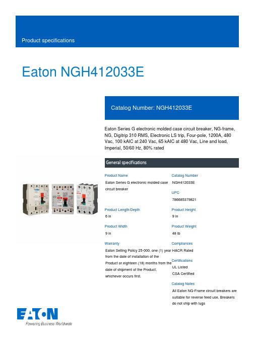
Eaton NGH412033EEaton Series G electronic molded case circuit breaker, NG-frame, NG, Digitrip 310 RMS, Electronic LS trip, Four-pole, 1200A, 480 Vac, 100 kAIC at 240 Vac, 65 kAIC at 480 Vac, Line and load, Imperial, 50/60 Hz, 80% ratedGeneral specificationsEaton Series G electronic molded case circuit breakerNGH412033E 7866853798216 in9 in9 in 48 lb Eaton Selling Policy 25-000, one (1) year from the date of installation of theProduct or eighteen (18) months from thedate of shipment of the Product,whichever occurs first.HACR Rated UL ListedCSA CertifiedAll Eaton NG-Frame circuit breakers are suitable for reverse feed use, Breakers do not ship with lugsProduct NameCatalog NumberUPCProduct Length/Depth Product Height Product Width Product Weight WarrantyCompliancesCertificationsCatalog Notes100 kAIC at 240 Vac 65 kAIC at 480 VacNG80% rated1200 AFour-poleSeries GImperialComplete breakerNG50 to 60 HzLine and load480 VacElectronic LS Application of Tap Rules to Molded Case Breaker Terminals Application of Multi-Wire Terminals for Molded Case Circuit BreakersMulti-wire lugs product aidHigh performance operating handles for Series G circuit breakers product aidCurrent limiting molded case circuit breaker module product aid Current limiting molded case circuit breaker module for series G, JG and CLSeries G MCCB quick selectorMOEM MCCB Product Selection GuideStrandAble terminals product aidMolded case circuit breakers providing higher levels of selective coordination product aidMotor protection circuit breakers product aidCircuit breaker motor operators product aidComprehensive circuit protection for control panel applicationsPower metering and monitoring with Modbus RTU product aidPlug-in adapters for molded case circuit breakers product aidJ-Frame 310+ and L-Frame 310+ Molded-case circuit breakers Breaker service centersSeries G Terminations and AccessoriesMolded case circuit breakers catalogEaton's Volume 4—Circuit ProtectionNG-frame Molded Case Circuit Breaker DrawingInstruction Leaflet for Drawout Cassette for NG Frame Circuit BreakersMOEM MCCB product selection guideEaton Specification Sheet - NGH412033ENG and ND-Frame molded case circuit breakersSeries G N-Frame 320-1600A, 240-690V Time Current CurvesInterrupt rating FrameRatingAmperage Rating Number of poles SeriesMounting hardware TypeCircuit breaker type Frequency rating TerminalsVoltage ratingTrip Type Application notesBrochuresCatalogsDrawingsInstallation instructions Specifications and datasheetsTechnical service bulletinsEaton Corporation plc Eaton House30 Pembroke Road Dublin 4, Ireland © 2023 Eaton. All Rights Reserved. Eaton is a registered trademark.All other trademarks areproperty of their respectiveowners./socialmedia。
Eaton GHB3100V 系列综合模具外壳电路保护器说明说明书

Eaton GHB3100VEaton Series C complete molded case circuit breaker, G-frame, GHB, Complete breaker, Fixed thermal, fixed magnetic trip, Three-pole, 100A, 480Y/277 Vac, 125/250 Vdc, 65 kAIC at 240 Vac, 14 kAIC at 480Y/277 Vac, 50°C, 50/60 HzGeneral specificationsEaton Series C complete molded case circuit breakerGHB3100V 7821149909712.63 in 4 in3 in 1.8 lb Eaton Selling Policy 25-000, one (1) year from the date of installation of theProduct or eighteen (18) months from thedate of shipment of the Product,whichever occurs first.Federal Specifications Classification W-C375BUL ListedProduct NameCatalog Number UPCProduct Length/Depth Product Height Product Width Product Weight WarrantyCompliancesCertificationsSeries C14 kAIC at 480Y/277 Vac65 kAIC at 240 VacMolded case circuit breaker GGHB50/60 HzComplete breaker50°C480Y/277 Vac, 125/250 Vdc 100 AFixed thermal, fixed magnetic Three-pole Application of Tap Rules to Molded Case Breaker Terminals Application of Multi-Wire Terminals for Molded Case Circuit Breakers UL listed 100%-rated molded case circuit breakersPower metering and monitoring with Modbus RTU product aid Circuit breaker motor operators product aidMulti-wire lugs product aidPlug-in adapters for molded case circuit breakers product aid StrandAble terminals product aidMotor protection circuit breakers product aidCurrent limiting Series C molded case circuit breakers product aid Breaker service centersMolded case circuit breakers catalogEaton's Volume 4—Circuit ProtectionSeries C GB/GHB/GDB Circuit Breakers - ILCircuit Breakers ExplainedCircuit breakers explainedSeries C J-Frame molded case circuit breakers time current curves Series C F-Frame molded case circuit breakersMOEM MCCB product selection guideSeries C G-Frame molded case circuit breakers time current curves Eaton Specification Sheet - GHB3100VSelling Policy 25-000 - Distribution and Control Products and ServicesSeriesInterrupt ratingTypeFrameCircuit breaker type Frequency ratingCircuit breaker frame type CalibrationVoltage rating Amperage RatingTrip TypeNumber of poles Application notesBrochuresCatalogsInstallation instructions MultimediaSpecifications and datasheets Warranty guidesEaton Corporation plc Eaton House30 Pembroke Road Dublin 4, Ireland © 2023 Eaton. All Rights Reserved. Eaton is a registered trademark.All other trademarks areproperty of their respectiveowners./socialmedia。
Eaton RGH325039E电子模具式电路保护器说明书
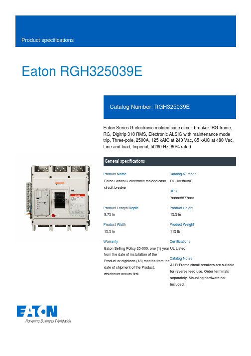
Eaton RGH325039EEaton Series G electronic molded case circuit breaker, RG-frame, RG, Digitrip 310 RMS, Electronic ALSIG with maintenance mode trip, Three-pole, 2500A, 125 kAIC at 240 Vac, 65 kAIC at 480 Vac, Line and load, Imperial, 50/60 Hz, 80% ratedGeneral specificationsEaton Series G electronic molded case circuit breakerRGH325039E 7866855778839.75 in 15.5 in 15.5 in 115 lb Eaton Selling Policy 25-000, one (1) year from the date of installation of theProduct or eighteen (18) months from thedate of shipment of the Product,whichever occurs first.UL Listed All R-Frame circuit breakers are suitablefor reverse feed use. Order terminalsseparately. Mounting hardware notincluded.Product NameCatalog NumberUPCProduct Length/Depth Product Height Product Width Product Weight WarrantyCertificationsCatalog Notes80% rated65 kAIC at 480 Vac125 kAIC at 240 VacComplete breakerRG80% ratedComplete breakerLine and load2500 AElectronic ALSIG with maintenance mode Three-pole Application of Tap Rules to Molded Case Breaker Terminals Application of Multi-Wire Terminals for Molded Case Circuit BreakersMulti-wire lugs product aidHigh performance operating handles for Series G circuit breakers product aidPlug-in adapters for molded case circuit breakers product aidMOEM MCCB Product Selection GuideCurrent limiting molded case circuit breaker module product aid Molded case circuit breakers providing higher levels of selective coordination product aidMotor protection circuit breakers product aidSeries G MCCB quick selectorStrandAble terminals product aidCurrent limiting molded case circuit breaker module for series G, JG and CLPower metering and monitoring with Modbus RTU product aid Comprehensive circuit protection for control panel applicationsCircuit breaker motor operators product aidBreaker service centersJ-Frame 310+ and L-Frame 310+ Molded-case circuit breakersSeries G Terminations and AccessoriesEaton's Volume 4—Circuit ProtectionMolded case circuit breakers catalogRG-frame Molded Case Circuit Breaker DrawingNG and ND-Frame molded case circuit breakersEaton Specification Sheet - RGH325039EMOEM MCCB product selection guideSeries G R-Frame 800-2500A, 240-690V Time Current CurveSeriesInterrupt ratingTypeCircuit breaker type RatingCircuit breaker frame type TerminalsAmperage RatingTrip TypeNumber of poles Application notesBrochuresCatalogsDrawingsSpecifications and datasheets Time/current curvesEaton Corporation plc Eaton House30 Pembroke Road Dublin 4, Ireland © 2023 Eaton. All Rights Reserved. Eaton is a registered trademark.All other trademarks areproperty of their respectiveowners./socialmedia。
Eaton Series C 模具电路保护器 JD3250KYD04 产品数据手册说明书
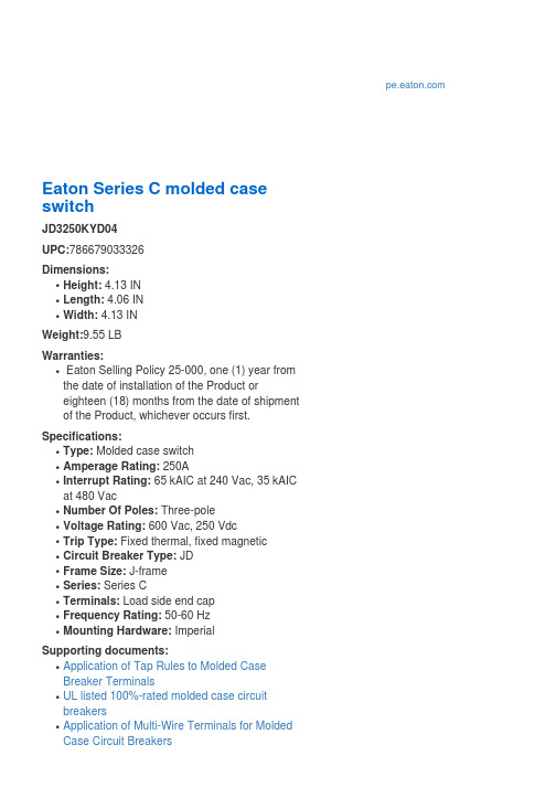
q Plug-in adapters for molded case circuit breakers product aid
q Multi-wire lugs product aid q Current limiting Series C molded case circuit
SACE Tmax XT 型号的模具式电路保护器产品说明书
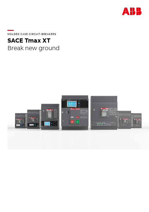
—MOLDED C A SE CIRCUIT-BRE AKERS SACE Tmax XTBreak new groundS ACE TM A X X T M O L D ED C A SE CI R C U IT-B R E A K ER S (M CCB S)—A molded case circuit-breaker range that ensures extreme performance and protection features up to 1600A. Designed to maximize ease of use, integration and connectivity. Built to deliver safety, reliability and quality.—Table of contents004 – 005SACE Tmax XT006 – 007Added values008 – 009Key features012 – 013Choosing the right product 014 – 015 Accessories018 – 021Products in detail024 – 025E lectronic trip units—SACE Tmax XTThe right choice: a complete circuit-breaker range for any solutionSACE Tmax XT2SACE Tmax XT5SACE Tmax XT7SACE Tmax XT44S ACE TM A X X T M O L D ED C A SE CI R C U IT-B R E A K ER S (M CCB S)5SACE Tmax XT3SACE Tmax XT1 SACE Tmax XT66S ACE TM A X X T M O L D ED C A SE CI R C U IT-B R E A K ER S (M CCBS)There is a lot more to the range of SACE Tmax XT than what meets the eye, and the benefits for your business are notice-able. To start with, the whole selection and ordering process has been overhauled to make it far easier to get your hands on the parts you need, speeding things up by about 30%. Installation has been simplified to increase user-friendliness, frames have been streamlined to save space, and improved connectivity - such as Bluetooth and Ekip mobile - will save you considerable time. Another additional benefit is the reliable cloud connectivity and overall increase in information available, meaning diagnostics and maintenance are vastly improved, resulting in less downtime. Finally, thanks to the smart power controller concept, overall energy consumption can be reduced by up to 20%.—Added value each step of the way There is more than just a circuit-breaker in the SACE Tmax XT rangeA new generation of molded case circuit-breakers delivering great added value.7Continuous operationOptimuminterfaceSafety and protectionSpeed up your projects OptimizedlogisticsSpace savingSpeed up your projects Easy toinstallContinuous operation EnergyefficiencyCommissioningThe SACE Tmax XT range offers the potential to save serious time. Thanks to simplified installation of frames, integrating the circuit-breakers into a communication network, trip unit settings per-formed via LCD and Bluetooth and Ekip Mobile con-nectivity , you stand to save up to 40% time overall.Diagnostics and maintenanceWith up to 30% more data available on the cloud and ABB unique power controller concept, it is far easier to diagnose problems and carry out necessary maintenance. This helps to prevent faults, restore energy more quickly and avoid any unnecessary charging of utilities.Energy savingThe SACE Tmax XT range comes with the exclu-sive ABB-patented Ekip Power Controller which monitors installation loads and can limit the amount of power consumed at any time. The result is an overall reduction in power consump-tion of up to 20% and lower energy bills. Further-more, you have 1% energy measurement accuracy according to IEC 61557-12.Selection, ordering and handling 30% faster thanks to part numbersreduction (-10%), online configurator (-40% time) and smart packaging (-30% space).A D D ED VA LU ES8S ACE TM A X X T M O L D ED C A SE CI R C U IT-B R E A K ER S (M CCB S)—01 Choose and custom-ize exactly the rightproducts for your needs, based on how you will use them. 10,000 solutions in one click —02 Effective energy management: 20% less power consump-tion with Power Controller enabled —03 Top reliability:Products designed and tested to exceed stan-dard requirements. More than 30 certificationsCloud-connectedTailor-madetechnologyCloud-connectedBeing connected is a key feature of today’s tech-nology and the SACE Tmax XT range of circuit- breakers offers more than just standalone pro-tection. Being considered key elements of an electrical distribution system, Tmax XT circuit- breakers give you the ability to monitor andmanage a wealth of information, easily, wherever you are. So even when on the road, anytime of the day or night, the power of full-access flexi-bility is in your hands.—Being able to monitor everything while being off-site provides a genuine feeling of you being in control at all times.Tailor-made solutionsJust because your project is complex, this does not mean your circuit-breaker setup has to be. All frames from XT1 to XT7 provide a common pro d uct experience that is backed up by a com-prehensive range of accessories with intuitive interfaces and ergonomic design. With maximum Outstanding technologyFlexibility is nothing without performance and the SACE Tmax XT range is able to deal with the most extreme breaking capacities, regardless of operating voltage, application, and environmen-tal conditions. Combined with the most precise electronic trip units in the smallest of frames, this ensures continuity of service and equipment pro-tection at all times.Top-level qualityAlmost a century of research and experience results in highly-reliable, top-level products that are ready to face all future challenges. Products like the SACE Tmax XT range set standards for edge technologies. Safety, product quality and reliability under pressure are fundamental to all ABB prod-ucts and the SACE Tmax XT range is no different.—Break new ground Key features of an outstanding product9—01—03—02—E A S E OF US E A N D I NS TA LL ATI O NMaximum flexibility for every application – SACE Tmax XT sets the new standard for electrical installations.Easy selection, one-size-fits-all accessories and intuitive design pave the way for smart manufacturing of panels and fast upgrades. Even for the most critical projects.12S ACE TM A X X T M O L D ED C A SE CI R C U IT-B R E A K ER S (M CCBS)Heavy duty Basic functionalityThermal-magnetic, Ekip DipEkip Touch/Hi-Touch —• Standard performance• Icu 70kA at 415/480V AC —• Extreme breaking capacity • 200kA at 415V AC• 100kA at 690V AC—Thermal-magnetic• TMF - TMD - TMA - TMG - MF - MAElectronic• Ekip Dip LIG - LS/I - LSI - LSIG -G Dip LS/I - M Dip I - M Dip LIU -M Dip LRIUNo communication/No display —Ekip Touch • LSI - LSIG - G Touch LSIG - M Touch LRIU - + Energy M Ekip Hi-Touch • LSI - LSIG - G Hi-Touch LSIG Full connectivity - Advanced logic - Power managementUniversally compatibleThe world of circuit-breakers is a complex one,yet choosing the right device for your individualneeds has never been simpler thanks to SACETmax XT range. Maybe you are looking for a basicprotection device for a standard distributionplant. Or perhaps you need something morecomplex, such as a device that integrates —Choosing the right circuit-breaker has never been so easyYou consider what you need. We’ll show you what is possible.protection, automation, measuring and commu-nication into a cloud-based supervision system. Whatever you are looking for, with a wealth of customization possibilities and a range of possible solutions depending on the breaking part and trip unit you choose, the power of circuit breakingis firmly in your hands.Possible combinations within the rangeBasic functionalityWhether you are a hotel owner or planning a production line,where you need to consider the overall power voltage over aperiod of time, the whole SACE Tmax XT range offers all thecircuit breaking power you need to keep your business run-ning long into the future.Thermal-magnetic, Ekip Dip – manual operationThis either consists of the standard thermal-magnetic tripunit intended for basic protection or the Ekip Dip trip unit,the first level of electronic trip unit that can provide in-creased accuracy, a wider regulation range, delayedshort-circuit protection and individual trip information.Heavy duty When it comes to heavy duty usage – whether it’s ships, chemical parks, mining, or heavy duty machinery – the SACE Tmax XT2, XT4, XT5 and XT7 frames are designed to work well beyond the normal constraints when you will be pushing the limits of your installation to the maximum.Ekip Touch/Hi-Touch – cloud functionality Once you are working with the XT2, XT4 XT5 or XT7 frames, all activity can be remotely monitored via the cloud thanks to the Ekip Touch/Hi-Touch trip units which send all data to the ABB Ability TM EDCS and can be monitored through smart-phone or tablet whenever and wherever you like.CH O OSI N G TH E R I G HT PR O D U C T13Tmax XT1Tmax XT2Tmax XT3Tmax XT4Tmax XT5Tmax XT6Tmax XT7Basic functionality (Icu@415V<70 kA)Heavy duty (Icu@415V>70 kA)Thermal-magnetic trip units Ekip Dip (standard electronic)Ekip Touch/Hi-Touch (smart electronic)14S ACE TM A X X T M O L D ED C A SE CI R C U IT-B R E A K ER S (M CCB S)—Udipsusam esciis pariamet, que et faci quia conet, sit magnatia dolora esciis pariamet, que et faci solupiste dollorpostem pliqui cum image—AccessoriesExpand the capabilities of the SACE Tmax XT rangeIntegrating circuit-breakers into any installation requires different levels of optimization. Whether physical, electrical, operational or safety-focused, accessories take SACE Tmax XT to the next level.AccessoriesA large range of connections has been conceived to match the most common distribution systems. Auxiliary contacts can provide precise information regarding breaker status and plant conditions, maximizing operator awareness and the overall accuracy of a supervision system. In addition, dif-ferent types of coils and motor operator versions, designed to operate with the most common voltage sources and reduced power consumption, enable the possibility to control all installations remotely. Residual current devices up to 630A, sig-naling modules, installation components (e.g. phase barriers, terminal covers), key-locks and padlocks are just a few examples of the care taken to safeguard appliances and operators alike. Metering15Various accessories are also available:1. Breaking unit2. Trip units3. Front4. Polish plate5. Terminal covers6. Auxiliary contacts7. Key lock8. Service releases9. Communication module10. C onversion kit for plug-in/withdrawable versions11. G uide of fixed part in thewithdrawable version 12. Fixed part - FP 13. Front for lever operating mechanism - FLD 14. Stored energy motor operator - MOE 15. Direct rotary handle - RHD 16. Transmitted rotary handle - RHE 17. Conversion kit RHE > RHS 18. Cable rack 19. Phase separators 20. R ear orientated terminals - R 21. F ront extended spread terminals - ES 22. Front terminals for copper-aluminium - FC CuAl 23. Front extended terminals - EF 24. Residual current release2419162122231761012911723138520151418415ACCE SSO R IE SS ACE TM A X X T M O L D ED C A SE CI R C U IT-B R E A K ER S (M CCB S)—PER FO R M A NCE A N D PROTEC TI O NContinuity of service and equipmentprotection – SACE Tmax XT sets the new standard when extreme breaking capacity is needed. Sharing the same logic, interfaces andfeatures regardless of operating voltageand environmental conditions. Embeddingthe most advanced protection into thesmallest of frames.S ACE TM A X X T M O L D ED C A SE CI R C U IT-B R E A K ER S (M CCB S)SACE Tmax XT1The founderSmall, reliable, versatile. Your reliable partner for all standard applications.At a glance:• Up to 160A• For basic functionalities• Dimensions 76.2x70x130 (WxDxH mm)• Thermal-magnetic trip unit SACE Tmax XT2The aspirerCompact yet powerful. It fits everywhere and is able to deal with all complex tasks. At a glance:• Up to 160A• For heavy duty• Dimensions 90x82.5x130 (WxDxH mm)• Thermal-magnetic, Ekip Dip,Ekip Touch/Hi-Touch18—The SACE Tmax XT range at a glance The world of circuit breaking and circuit protection in your handsThe SACE Tmax XT range takes circuit protection to the nextlevel. Designed to perform at extremely high levels, simpleto install and able to provide increasingly better safety,there is a frame to meet each and every one of your require-ments. From a basic solution for standard applications -such as hotels - through to advanced, heavy-duty applica-tions with cloud connectivity for ships, chemical parks orairports, the new range has got it covered: securely, profes-sionally, reliably.19PR O D U C TS I N D E TA I LSACE Tmax XT4The entrepreneur A forward-thinking, multitasker. It finds solutions for all levels of complexity.At a glance:• Up to 250A • For heavy duty • Dimensions 105x82.5x160 (WxDxH mm)• Thermal-magnetic, Ekip Dip,Ekip Touch/Hi-TouchSACE Tmax XT3The workhorseSmall and experienced. For standardapplications that need few efforts.At a glance:• Up to 250 A• For basic functionalities• Dimensions 105x70x150 (WxDxH mm)•Thermal-magnetic trip unitS ACE TM A X X T M O L D ED C A SE CI R C U IT-B R E A K ER S (M CCBS)SACE Tmax XT5The gamechanger.Compact, extremely powerful and flexible. It shows the world what a circuit-breaker of the future can do, today. At a glance:• Up to 630A• For heavy duty• Dimensions 140x103x205 (WxDxH mm)• Thermal-magnetic, Ekip Dip, Ekip Touch/Hi-Touch SACE Tmax XT6The carpenterBuilt to last. It completes all assignments it has been entrusted with.At a glance:• Up to 1000A• For basic functionalities• Dimensions 210x103.5x268 (WxDxH mm)• Thermal-magnetic, Ekip Dip2021PR O D U C TS I N D E TA I LSACE Tmax XT7 M The motorized superhero The ultimate choice, with motor. It deals with the most heavy-duty demands smoothly.At a glance:• Up to 1600A • For heavy duty • Dimensions 210x178x268 (WxDxH mm)• Ekip Dip, Ekip Touch/Hi-TouchSACE Tmax XT7The superheroThe ultimate choice. It deals with the mostheavy-duty demands effortlessly.At a glance:• Up to 1600A• For heavy duty• Dimensions 210x166x268 (WxDxH mm)•Ekip Dip, Ekip Touch/Hi-TouchS ACE TM A X X T M O L D ED C A SE CI R C U IT-B R E A K ER S (M CCB S)—DATA A N D CO N N EC TI V IT YPlant management of the future – SACE Tmax XT sets the new standard in modern plant and energy management. Access, monitor and control information remotely, anywhere, at any time. Improving efficiency and saving energy.24S ACE TM A X X T M O L D ED C A SE CI R C U IT-B R E A K ER S (M CCB S)—01 All the tools neededto set up a compe-tent and effectiveenergy managementstrategy. 30% moreinformation abouta running system toempower ABB Ability TM P r o t e c t i o n a n di n f o r m a t i o n AccuracyThermal-magnetic trip units Thermal-magnetic trip units are intended for the protection of AC and DC networks. They are a solution for basic protection such as overloads and short-circuits.Ekip Dip trip unitsEkip Dip trip units represent the first level ofelectronic trip unit and are used to protect ACnetworks. Compared to thermal-magnetic tripunits, they can provide increased accuracy, a widerreg ulation range, delayed short-circuit protection,in di v idual trip information and test capa bility.Ekip Touch/Hi-Touch trip units Ekip Touch/Hi-Touch trip units offer state-of-the-art technology for AC-network protection. These trip units integrate a great number of protection and automation functionalities, performed with best-in-class accuracy. Measurement and supervi-sion data can be transmitted both on the local communication network (the most popular com-munication protocols are available) or directly over the Internet. Configuration of the trip unit is extremely user-friendly, mainly on the sizes where a color touchscreen display is available. Furthermore, as operational requirements evolve,for the first time ever customers can downloadnew functions from the ABB Ability Marketplace TM ,choosing among more than fifty different protec-tion, metering and automation functionalities.—Electronic trip units Ekip Dip and Ekip Touch/Hi-Touch The network under controlWhen it comes to accurate protection of the network, you cannot go wrong with Ekip Dip and Touch technology.Trip unit rangeThe protection units available for the SACE Tmax XTrange is organized in three layers, characterizedby increasing performance, interfaces, informa-tion sets and integration functions. Each layerincludes several trip unit versions, designed to match specific application needs such as distribu-tion, generator protection and motor protection.25CampaignS ACE TM A X X T M O L D ED C A SE CI R C U IT-B R E A K ER S (M CCB S)—QUA LIT Y A N D R ELI A B I LIT YAbsolute attention to detail, withstyle – from design to manufacturing, SACETmax XT sets the new standard for edgetechnologies. Almost a century of research and experience means top-level products that areready to face future challenges.© Copyright 2019 ABB. All rights reserved.Specifications subject to change without notice.9A K K 107046A 3308 - 05/2019—ABB SACEElectrification business Smart Power business line 5, Via PescariaI-24123 Bergamo - ItalyPhone: +39 035 395-111go.abb/xt。
- 1、下载文档前请自行甄别文档内容的完整性,平台不提供额外的编辑、内容补充、找答案等附加服务。
- 2、"仅部分预览"的文档,不可在线预览部分如存在完整性等问题,可反馈申请退款(可完整预览的文档不适用该条件!)。
- 3、如文档侵犯您的权益,请联系客服反馈,我们会尽快为您处理(人工客服工作时间:9:00-18:30)。
5. 故障现象及处理流程............................................................................................. 25 6. 免责声明................................................................................................................. 27
厦门维动信息科技有限公司
MP 系列模具保护器
用户手册
MP 模具保护器 用户手册
厦门维动信息科技有限公司
版本:V1.0 更新:2013-4-17
产品用户手册
Xiamen Weidong Info. Tec. Co., Ltd.
~ 1~
பைடு நூலகம்门维动信息科技有限公司
MP 系列模具保护器
用户手册
目
1.1 1.2 1.3
2. 安全操作须知........................................................................................................... 4
2.1 2.2 2.3 2.4 2.5 3.1 3.2 3.3 3.4 4.1 使用环境要求 ............................................................................................................... 4 安装注意事项 ............................................................................................................... 4 调试注意事项 ............................................................................................................... 4 使用中注意事项 ........................................................................................................... 4 维护保养事项 ............................................................................................................... 4 主控制器检查和固定 ................................................................................................... 5 主控制器电源接线 ....................................................................................................... 5 主控制器与注塑机接线 ............................................................................................... 5 相机和光源的安装 ....................................................................................................... 7
3. 模具保护器安装接线............................................................................................... 5
4. 模具保护器操作流程............................................................................................... 8
人机界面介绍 ............................................................................................................... 8 4.1.1 界面构成: ....................................................................................................... 8 4.1.2 状态区: ........................................................................................................... 8 4.1.3 图像区: ........................................................................................................... 9 4.1.4 功能区: ........................................................................................................... 9 4.1.5 “设置”窗口 ..................................................................................................... 11 4.1.6 “模型”窗口 ................................................................................................. 14 4.1.7 “示教”窗口 ................................................................................................. 16 4.1.8 “记录”窗口 ................................................................................................. 20 4.2 调试运行流程 ............................................................................................................. 20 4.2.1 调试全流程 ..................................................................................................... 20 4.2.2 相机和光源调试 ............................................................................................. 21 4.2.3 检测设定 ......................................................................................................... 21 4.2.4 模型设定 ......................................................................................................... 21 4.2.5 标准图设定 ..................................................................................................... 21 4.2.6 监测区域(ROI)设定 .................................................................................. 22 4.2.7 自动监视 ......................................................................................................... 22 4.2.8 监视异常处理 ................................................................................................. 22
录
1. MP 系列模具保护器简介 ......................................................................................... 1
功能介绍....................................................................................................................... 1 产品型号含义说明 ....................................................................................................... 2 主要技术指标 ............................................................................................................... 2 1.3.1 环境指标 ........................................................................................................... 2 1.3.2 物理参数 ........................................................................................................... 2 1.3.3 性能参数 ........................................................................................................... 2 1.4 内部、外部接口描述 ................................................................................................... 3 1.5 供货清单....................................................................................................................... 3