Turck 模块LED指示灯说明
巴鲁夫主站模块指示灯说明书

巴鲁夫主站模块指示灯说明书摘要:1.巴鲁夫主站模块指示灯说明书概述2.巴鲁夫主站模块指示灯的功能和特点3.巴鲁夫主站模块指示灯的使用方法4.巴鲁夫主站模块指示灯的维护和保养5.巴鲁夫主站模块指示灯的注意事项正文:【巴鲁夫主站模块指示灯说明书概述】巴鲁夫主站模块指示灯是一种工业用指示灯,主要用于指示设备的运行状态。
本说明书旨在向用户介绍如何正确使用和维护巴鲁夫主站模块指示灯,以确保设备的正常运行和使用寿命。
【巴鲁夫主站模块指示灯的功能和特点】巴鲁夫主站模块指示灯具有以下功能和特点:1.明亮的指示效果:巴鲁夫主站模块指示灯采用高亮度LED 灯珠,能够在各种环境下清晰地指示设备的运行状态。
2.稳定的工作性能:巴鲁夫主站模块指示灯具有优良的抗干扰性能,能够在各种复杂的电气环境中稳定工作。
3.长的使用寿命:巴鲁夫主站模块指示灯采用优质的LED 灯珠,具有长达10 万小时的使用寿命。
4.宽泛的适用范围:巴鲁夫主站模块指示灯可以应用于各种工业设备,如自动化生产线、机器人、电气柜等。
【巴鲁夫主站模块指示灯的使用方法】1.在使用巴鲁夫主站模块指示灯之前,请确保设备已经断电,并做好相关的安全防护措施。
2.根据设备的接线方式,将巴鲁夫主站模块指示灯的输入端与设备的控制电路相连接。
3.将巴鲁夫主站模块指示灯的输出端与设备的执行元件(如电磁阀、电机等)相连接。
4.接线完成后,合上电源开关,此时巴鲁夫主站模块指示灯应正常点亮。
5.在设备运行过程中,请注意观察巴鲁夫主站模块指示灯的状态,以判断设备的运行状况。
【巴鲁夫主站模块指示灯的维护和保养】1.定期检查巴鲁夫主站模块指示灯的连接线,确保接线牢固,避免因接线松动导致的设备故障。
2.如发现巴鲁夫主站模块指示灯亮度减弱或者不亮,请及时更换新的LED 灯珠。
3.在设备停机维护时,可以使用干净的湿布擦拭巴鲁夫主站模块指示灯表面,以保持其清洁。
【巴鲁夫主站模块指示灯的注意事项】1.在使用和维护巴鲁夫主站模块指示灯时,请确保手部干燥,避免触电事故。
图尔克流量开关说明书

TURCK流量开关现场调试说明——开关量或继电器输出流量状态指示灯电位计调节旋钮(上覆盖有白色的防尘帽)图尔克的标准型流量开关外形如图所示,黄色外壳上共有6个不同颜色的指示灯和一个电位计调节旋钮。
调试前需要做的准备:保证电位计旋钮上的白色塑料防尘帽已经拧下,可以看见传感器内部的铜质金属电位计旋钮;确定随流量开关附带的黄把小型螺丝刀在手边,或者与小型螺丝刀尺寸相同的工具也可;确定管道处于正常使用时的压力及温度状态。
调试步骤:一、确定满管基准流量状态:1.确定管道内压力和温度处于正常运行的状态下;2.此时将流量开关所在管道上的阀门打开至全开,然后等待30秒至1分钟,使流量开关内部电路记忆当前管道流量;3.用小螺丝刀调节电位计旋钮(顺时针旋动电位计旋钮灵敏度增大,指示灯点亮个数逐渐增加;逆时针旋动电位计旋钮灵敏度减小,指示灯点亮个数逐渐减少),直至所有指示灯刚好都点亮(刚好是指向逆时针方向旋动一点电位计,则最右边一个绿色指示灯就熄灭的临界状态);4.此时满管基准流量状态调节完毕。
二、设定报警(动作)点:注:流量开关在黄色指示灯和红色指示灯切换的时候会有动作输出。
首先确定使用过程中需要的设定点。
图尔克流量开关共有6个指示灯,其中每2个指示灯间有1个间隔,共有5个间隔,每个间隔代表20%的基准满管流量。
经过大量的现场验证,设定点为60%或40%的基准满管流量为最适合的设定值。
指示灯与百分比流量的对应关系:100% 对应4个绿灯1个黄灯亮;80% 对应3个绿灯1个黄灯亮;60% 对应2个绿灯1个黄灯亮;40% 对应1个绿灯1个黄灯亮;20% 仅对应1个黄灯亮。
在调节完满管基准流量后,可以进行报警点的设定。
步骤如下:1.调节流量开关所在管道上的阀门(一般为向关闭的方向调节),同时观察流量开关上的指示灯状态,根据指示灯与百分比流量的对应关系,直至指示灯的显示对应实际使用所需要的百分比流量(一般为40%或60%)时,停止调节阀门;2.等待30秒至1分钟,使流量开关内部电路记忆当前管道流量;3. 此时再调节电位计旋钮,分为两种情况:(1)如需正好到设定点报警,则再调节电位计旋钮直至一个红灯亮;(2)如需低于设定点报警,则再调节电位计旋钮直至一个黄灯亮。
元动波60型Tektus指光灯说明书

CCT
2700K / 3000K / 4000K
CRI
Ra90
SDCM
3
Luminous flux 2700K - Ra90: 1517lm (350mA) / 2118lm (500mA) LED (350/500mA) 3000K - Ra90: 1577lm (350mA) / 2202lm (500mA)
Tektus 45: Bridgelux Vero 10 LED (350mA)
CCT
2700K / 3000K / 4000K
CRI
Ra90 (Ra80 on request)
SDCM
3
Luminous Flux LED
2700K - Ra90: 1100lm (124lm/W) 3000K - Ra90: 1156lm (130lm/W)
DALI dim 350/500mA - Adjustable driver 490.26.20 incl. 2700K - Ra90 - 995lm / 1390lm 1075.AA.26.927.XX 3000K - Ra90 - 1035lm / 1445lm 1075.AA.26.930.XX 4000K - Ra90 - 1050lm / 1467lm 1075.AA.26.940.XX
Adjustable beam 25° - 46° Air circulation notice: Do not topload with insulation materials
Tektus 45 Recessed
PRICES INCL. DRIVERS
Non dim - Driver 490.24.16 incl. 2700K - Ra90 - 10.2W - 772lm 3000K - Ra90 - 10.2W - 811lm 4000K - Ra90 - 10.2W - 822lm
泰隆LED指示灯TL70产品说明说明书

InstructionManualBanner's TL70 Tower Light is a 70 mm, modular LED indicator with extremely bright and uniform light. The modularity gives the user flexibility to customize tower lights as needed and change positions in the field. The TL70 is also available preassembled for easy installation.•Light segments have user-selectable solid ON or flashing •Up to six colors, or five colors plus audible, in one device•Rugged, water-resistant IP65 housing with UV-stabilized material•Bright, uniform indicator segments appear gray when off to eliminate false indicationfrom ambient light•Several connection options to choose from including M12/Euro-style quick disconnect,cabled, and terminal-wiredModelsB-TL70Q5ConnectionHousingTL70 BaseTL70 SegmentsBase SegmentSG-TL70HousingTL70 SegmentHousing ColorBlank = Black C = Gray Housing ColorBlank = Black C = Gray RColor/Alarm5 = 2 m, 5-wire Integral Cable8 = 2 m, 8-wire Integral CableT = TerminalQ5 = 5-pin M12/Euro-style Integral QD Q8 = 8-pin M12/Euro-style Integral QDQP5 = 150 mm (5.9 in) cable with 5-pin M12/Euro-style QD QP8 = 150 mm (5.9 in) cable with 8-pin M12/Euro-style QDModels with a quick disconnect require a mating cordsetA = Standard Audible O = OrangeW = White AP = Programmable AudibleALM = Loud Multi-Tone Audible AL = Loud AudibleB = Blue R = Red G = GreenY = YellowSelect the 5-pin base for tower light configurations of up to 4 modules. Select the 8-pin base for tower light configurations of up to 6 modules.•Example base model number: B-TL70-Q5•Example light segment model number: SG-TL70-G •Example audible segment model number: SG-TL70-ATL70HousingTL70 Pre-Assembled ModelsW B G Y R OHousing Color Blank = BlackC = Gray Audible Alarm*Blank = None A = Standard AudibleQConnectionBlank = 2 m Integral Cable T = TerminalQ = M12/Euro-style Integral QDQP = 150 mm (5.9 in) cable with 5-pin M12/Euro-style QDModels with a quick disconnect require a mating cordsetColor/PositionO = OrangeW = White AP = Programmable Audible * not available with six-light modelsAL = Loud AudibleB = Blue R = Red G = Green Blank = None Y = Yellow 123456•Example pre-assembled model number: TL70GYRAQ.TL70 Modular Tower LightOriginal Document 182214 Rev. G12 October 2017182214Turn on the appropriate DIP switch to set the order of the components, counting up from the towerlight's base.Module 1Module 2Module 3Module 4Module 5Module 6BaseLight Module Flash Rate3 HzON OFF 1.5 Hz ON ON Solid On*OFF OFF Standard Audible Module SettingsPulse 1.5 HzON OFF Chirp Alarm ON ON Siren Alarm OFF ON Continuous Alarm*OFFOFF* Factory default setting - Tel: +1-763-544-3164P/N 182214 Rev. GTo assemble the modules:1.Align the notches on each module and presstogether.2.Rotate the top module clockwise to lock intoplace (notches shown in the locked position).Wiring DiagramsPNP InputNPN InputEuro-style Male Pinouts5Key1 = brown2 = white3 = blue4 = black5 = grayM1 = Module 1M2 = Module 2M3 = Module 3M4 = Module 4 PNP InputNPN InputEuro-style Male Pinouts2Key1 = white2 = brown3 = green4 = yellow5 = gray6 = pink7 = blue8 = redM1 = Module 1M2 = Module 2M3 = Module 3M4 = Module 4M5 = Module 5M6 = Module 6P/N 182214 Rev. G - Tel: +1-763-544-31643Wiring Terminal BlockTerminal Block Key0 = dc common 1 = Module 12 = Module 23 = Module 34 = Module 45 = Module 56 = Module 6SpecificationsSupply Voltage and Current12 V dc to 30 V dcSupply Protection CircuitryProtected against transient voltagesIndicators1 to 6 colors depending on model (Green, Red, Yellow, Blue, White, and Orange)LEDs are independently selectedFlash Rates: 1.5 Hz ±10% and 3 Hz ±10%Indicator Response TimeOff Response: 150 µs (maximum) at 12 to 30 V dcOn Response: 180 ms (maximum) at 12 V dc; 50 ms (maximum) at 30 V dcAudible AlarmStandard Audible: 2.6 kHz ± 250 Hz oscillation frequency; maximum intensity (typical) 92 dB at 1 m (3.3 ft)Loud Audible: 2.6 kHz ± 250 Hz oscillation frequency; maximum intensity (typical) at 1 m (3.3 ft) (see table)Audible AdjustmentStandard Audible: Rotate the cover until the desired volume is reached Loud Audible Alarm: Select the desired volume using DIP switches 9 and 10Typical Reduction in Sound Intensity with Audible Adjustment (maximum to minimum):•Standard Audible: 8 dB •Loud Audible: 16 dB ConstructionBases, Segments, Covers: polycarbonate - Tel: +1-763-544-3164P/N 182214 Rev. GIndicator CharacteristicsConnections5-pin M12/Euro-style quick disconnect connector, 8-pin M12/Euro-style quickdisconnect connector, 150 mm (5.9 in) PVC cable with an M12/Euro-style quickdisconnect connector, terminal block, or 2 m (6.5 ft) unterminated cable,depending on modelTerminal Block Models14 to 28 AWG wireOperating Conditions–40 °C to +50 °C (–40 °F to +122 °F)95% at +50 °C maximum relative humidity (non-condensing)Environmental RatingIEC IP65CertificationsVibration and Mechanical ShockVibration 10 Hz to 55 Hz 0.5 mm p-p amplitude per IEC 60068-2-6Shock 15G 11 ms duration, half sine wave per IEC 60068-2-27Required Overcurrent ProtectionWARNING: Electrical connections must be madeby qualified personnel in accordance with localand national electrical codes and regulations.Overcurrent protection is required to be provided by end product applicationper the supplied table.Overcurrent protection may be provided with external fusing or via CurrentLimiting, Class 2 Power Supply.Supply wiring leads < 24 AWG shall not be spliced.For additional product support, go to .DimensionsM30 × 1.5(mounting nutincluded)P/N 182214 Rev. G - Tel: +1-763-544-31645AccessoriesCordsetsAll measurements are listed in millimeters, unless noted otherwise. - Tel: +1-763-544-3164P/N 182214 Rev. GMounting BracketsAll measurements are listed in millimeters, unless noted otherwise.Elevated Mount SystemP/N 182214 Rev. G - Tel: +1-763-544-31647LMB Sealed Right-Angle BracketsBanner Engineering Corp. Limited WarrantyBanner Engineering Corp. warrants its products to be free from defects in material and workmanship for one year following the date of shipment. Banner Engineering Corp. will repair or replace, free of charge, any product of its manufacture which, at the time it is returned to the factory, is found to have been defective during the warranty period. This warranty does not cover damage or liability for misuse, abuse, or the improper application or installation of the Banner product.THIS LIMITED WARRANTY IS EXCLUSIVE AND IN LIEU OF ALL OTHER WARRANTIES WHETHER EXPRESS OR IMPLIED (INCLUDING, WITHOUT LIMITATION, ANY WARRANTY OF MERCHANTABILITY OR FITNESS FOR A PARTICULAR PURPOSE), AND WHETHER ARISING UNDER COURSE OF PERFORMANCE, COURSE OF DEALING OR TRADE USAGE.This Warranty is exclusive and limited to repair or, at the discretion of Banner Engineering Corp., replacement. IN NO EVENT SHALL BANNER ENGINEERING CORP. BE LIABLE TO BUYER OR ANY OTHER PERSON OR ENTITY FOR ANY EXTRA COSTS, EXPENSES, LOSSES, LOSS OF PROFITS, OR ANY INCIDENTAL, CONSEQUENTIAL OR SPECIAL DAMAGES RESULTING FROM ANY PRODUCT DEFECT OR FROM THE USE OR INABILITY TO USE THE PRODUCT, WHETHER ARISING IN CONTRACT OR WARRANTY, STATUTE, TORT, STRICT LIABILITY, NEGLIGENCE, OR OTHERWISE. Banner Engineering Corp. reserves the right to change, modify or improve the design of the product without assuming any obligations or liabilities relating to any product previously manufactured by Banner Engineering Corp. Any misuse, abuse, or improper application or installation of this product or use of the product for personal protection applications when the product is identified as not intended for such purposes will void the product warranty. Any modifications to this product without prior express approval by Banner Engineering Corp will void the product warranties. All specifications published in this document are subject to change; Banner reserves the right to modify product specifications or update documentation at any time. Specifications and product information in English supersede that which is provided in any other language. For the most recent version of any documentation, refer to:.© Banner Engineering Corp. All rights reserved。
列控板块指示灯意义
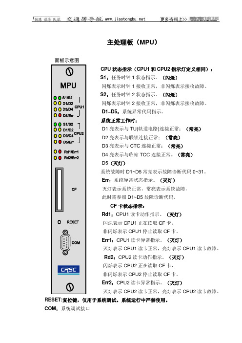
主处理板(MPU)面板示意图S1:任务时钟1状态指示。
(闪烁)闪烁表示时钟1接收正常,非闪烁表示接收故障。
S2:任务时钟2状态指示。
(闪烁)闪烁表示时钟2接收正常,非闪烁表示接收故障。
D1~D5:系统异常代码指示。
系统正常工作时:D1亮表示与TU(轨道电路)连接正常;(常亮)D2亮表示与联锁连接正常;(常亮)D3亮表示与CTC连接正常;(常亮)D4亮表示与临站TCC连接正常。
(常亮)D5(灭灯)系统故障时D1~D5常亮表示故障诊断代码0~31。
Err:系统异常状态指示。
(灭灯)灭灯表示系统正常,常亮表示系统故障,此时需参照D1~D5故障诊断代码。
CF卡状态指示:Rd1:CPU1读卡动作指示。
(灭灯)闪烁表示CPU1正在读取CF卡,非闪烁表示CPU1停止读取CF卡。
Err1:CPU1读卡异常指示。
(灭灯)灭灯表示CPU1读卡正常,亮灯表示CPU1读卡故障。
Rd2:CPU2读卡动作指示。
(灭灯)闪烁表示CPU2正在读取CF卡,非闪烁表示CPU2停止读取CF卡。
Err2:CPU2读卡异常指示。
(灭灯)灭灯表示CPU2读卡正常,亮灯表示CPU2读卡故障。
RESET:复位键,仅用于系统调试。
系统运行中严禁使用。
COM:系统调试接口安全监视板(VSU)Array U1:CPU1状态指示U2:CPU2状态指示,U1和U2指示灯定义相同5V:5V电源状态指示(灭灯)灭灯表示检测正常,亮灯表示检测故障。
24V:24V电源状态指示(灭灯)灭灯表示检测正常,亮灯表示检测故障。
A LL:完整性状态指示(灭灯)亮灯表示检测正常,灭灯表示检测故障。
R LY:安全电源状态指示。
(灭灯)亮灯表示检测正常,灭灯表示检测故障。
L1:任务时钟1状态指示闪烁表示生命信号1接收正常,非闪烁表示接收故障L2:任务时钟2状态指示闪烁表示生命信号2接收正常,非闪烁表示接收故障L3:任务时钟3状态指示闪烁表示生命信号3接收正常,非闪烁表示接收故障注:L1、L2、L3平时交替闪烁L4(备用):任务时钟4状态指示(灭灯)闪烁表示生命信号4接收正常,非闪烁表示接收故障Syn1:同步时钟1状态指示闪烁表示同步时钟1发送正常,非闪烁表示发送故障Syn2:同步时钟2状态指示闪烁表示同步时钟2发送正常,非闪烁表示发送故障Syn1 和Syn2交替闪烁面板示意图CAN网络通信卡(CIU)面板示意图S1:任务时钟状态指示闪烁表示任务时钟1接收正常,非闪烁表示接收故障。
TURCK智能温度传感器操作说明

改变输出1状态的下限值 磁滞模式(N/O=常开) 磁滞模式(N/C=常闭) 窗口模式(N/O=常开) 窗口模式(N/C=常闭) 改变输出2状态的上限值 改变输出2状态的下限值 磁滞模式(N/O=常开) 磁滞模式(N/C=常闭) 窗口模式(N/O=常开) 窗口模式(N/C=常闭)
仅限图尔克公司内部使用
For Internal Use Only
rP
关状态,不受压力波动设定点影 响,开关范围可由用户通过开关 点(SP)和释放点(rSP)设定。
参数解释 Loc 编程模式锁定 ULoc 可编程模式 Uni 单位显示
SP1 开关点1
选项
℃ F K Ohm
rP1 OU1
SP2 rP2 OU2
ASP
释放点1 输出1模式
开关点2 释放点2 输出2模式
模拟量输出
如果您想改变设定值,请按压“Set”键并保 持5S直到屏幕停止闪烁。再通过 ↑或↓键选 择。
最后通过按压隐藏按钮“Enter”保存设定值。 新的设定立即生效。
Ohm
K
F
℃
F K Ohm
℃
℃ F K Ohm
锁定/解锁 该传感器可通过设定来防止误进入菜单和编程 模式。 锁定:Mode+Set 10S
解锁:Mode+Set 10S
dS2 SP2的开关延迟
dr2 rP2的开关延迟
Fou1 Fou2
P-n diS
rEs SOF
断路或短路输出 状态 断路或短路输出 状态
测量值显示 响应时间
Fou1=on Fou1=oFF Fou2=on Fou2=oFF
Fou2=on Fou2=oFF
Fou2=on Fou2=oFF pnp npn
Turck 聚焦光电传感器 Q45AD9CV4Q 说明书
T 03:11:44+02:00型号Q45AD9CV4Q 货号3037634工作模式聚焦传感器发光模式红波长680 nm 焦距100 mm 环境温度-40…+70 °C 电压Nom. 8.2 VDC 无激励电流损耗ð 1 mA 激励电流损耗ï 2.1 mA 空载电流 I 0ð 2.1 mA输出性能亮态, NAMUR 开关频率ð 100 Hz防爆标志防爆标识为Ex II 1G 和 Ex ia IIC T5设计方型, Q45尺寸56.4x 44.5x 102.6 mm 外壳材料塑料, PBT 镜头塑料, 丙烯酸连接接插件, M12 x 1防护等级IP67MTTF 67 years 符合SN 29500 (Ed. 99) 40 °C认证防爆类型Ex ia IIC T6防爆认证KEMA 03ATEX 1441 X 开关状态指示LED指示灯 红sATEX 防爆认证 II组设备,设备等级1G,可用为气体危险0区s M12 x 1针头接插件s 防护等级IP67s 通过电位计可调节灵敏度s 工作电压:5…15 VDCs 本安输出:暗态<= 1.2 mA ;亮态 >= 2.1 mA s符合EN 60947-5-6(NAMUR)标准接线图功能原理聚焦式传感器是通过发射器前的镜头聚焦一个光点来检测的。
类似于直反式传感器,被测物返回的光被检测。
聚焦式传感器完美的应用于检测细小物体或色标检测和透明物体位置检测。
被测物必须位于焦点范围内。
焦距被定义为焦点和传感器之间的距离,被测物在焦点上能被监测到。
基于聚焦式传感器汇聚于一点的特点,聚焦式传感器能检测反射率低的被测物。
过量增益曲线过量增益相关距离。
T 03:11:44+02:00附件型号货号尺寸图IM1-22EX-R/24VDC7541210双通道隔离开关放大器;输入NAMUR信号;可选开/关断路和短路监控模式;信号输出模式(常开/常闭)可选;可插拔接线端子;18mm宽度;24VDC电压供电SMB30A 3032723不锈钢安装支架,适用30mm圆柱传感器SMB30FAM103011185安装支架,材质不锈钢,适用M10 x 1.5螺纹,螺纹长度30mmSMB30SC 3052521安装支架,PBT 黑;适用于 30mm 圆柱形传感器;4 个螺丝M5 x 0.8T 03:11:44+02:00操作手册符合标准该传感器符合94/9/EC规定,并且符合欧洲的EN60079-0:2009和EN60079-11:2012、EN60079-26:2007标准,适合于防爆危险区域的应用。
Turck BI5-Q08-Y1X 产品说明书
T 04:55:16+02:00Type code BI5-Q08-Y1X Ident no.4054000Rated operating distance Sn 5 mm Mounting condition flushAssured sensing range ð (0,81 x Sn) mmCorrection factors St37 = 1; Al = 0.3; stainless steel = 0.7; Ms = 0.4Repeatability ð 2 % of full scale Temperature drift 10 %Hysteresis1…10 %Ambient temperature-25…+70 °C Output function 2-wire, NAMUR Switching frequency 1 kHzVoltageNom. 8.2 VDC Non-actuated current consumption ï 2.1 mA Actuated current consumptionð 1.2 mAApproval acc. toKEMA 02 ATEX 1090X Internal capacitance (C ) / inductance (L )150 nF / 150 µHDevice designationÉ II 2 G Ex ia IIC T6 Gb / II 1 D Ex ia IIIC T95 °C Da(max. U = 20 V, I = 60 mA, P = 130 mW)Design rectangular, Q08Dimensions32 x 20 x 8 mm Housing material metal, GD-Zn Connection cableCable quality4 mm, blue, Lif9YYW, PVC, 2 mCable cross section 2 x 0.25 mm Vibration resistance 55 Hz (1 mm)Shock resistance 30 g (11 ms)Protection class IP67MTTF6198 years acc. to SN 29500 (Ed. 99) 40 °C Switching stateLED yellows ATEX category II 2 G, Ex zone 1s ATEX category II 1 D, Ex zone 20s SIL2 as per IEC 61508s Rectangular, height 8 mm s Active face on top s Metall, zinc die casting s DC 2-wire, nom. 8.2 VDCsOutput acc. to DIN EN 60947-5-6 (NA-MUR)sCable connectionWiring diagramFunctional principleInductive sensors detect metal objects con-tactless and wear-free. For this, they use a high-frequency electromagnetic AC field that interacts with the target. Inductive sensors generate this field via an RLC circuit with a ferrite coil.We offer special versions for temperatures of -60 °C up to +250 °C.T 04:55:16+02:00Distance D 2 x B Distance W 3 x Sn Distance S 1 x B Distance G6 x Sn Width of the active face B20 mmT 04:55:16+02:00AccessoriesType codeIdent no.DescriptionDimension drawingIM1-22EX-R7541231Isolating switching amplifier, dual-channel; 2 relay outputs NO; input NAMUR signal; selectable ON/OFF mode for wire-break and short-circuit monitoring; adjustable signal flow (NO/ NC mode); removable terminal blocks; 18 mm width;universal voltage supply unitT 04:55:16+02:00Operating manual Intended useThis device fulfills the directive 94/9/EC and is suited for use in explosion hazardous areas according to EN60079-0:2012, -11:2012, -26:2007.Further it is suited for use in safety-related systems, including SIL2 as per IEC 61508.In order to ensure correct operation to the intended purpose it is required to observe the national regulations and directives.For use in explosion hazardous areas conform to classificationII 2 G and II 1 D (Group II, Category 2 G, electrical equipment for gaseous atmospheres and category 1 D, electrical equipment for dust atmo-spheres).Marking (see device or technical data sheet)É II 2 G acc. to Ex ia IIC T6 Gb acc. to EN60079-0 and -26 und É II 1 D Ex ia IIIC T95°C Da acc. to EN60079-0Local admissible ambient temperature -25…+70 °CInstallation / CommissioningThese devices may only be installed, connected and operated by trained and qualified staff. Qualified staff must have knowledge of protection classes, directives and regulations concerning electrical equipment designed for use in explosion hazardous areas.Please verify that the classification and the marking on the device comply with the actual application conditions.This device is only suited for connection to approved Exi circuits compliant to EN60079-0 and -11. Please observe the maximum admissible electrical values.After connection to other circuits the sensor may no longer be used in Exi installations. When interconnected to (associated) electrical equip-ment, it is required to perform the "Proof of intrinsic safety" (EN60079-14).When employed in safety systems to IEC 51408 it is required to assess the failure probability (PFD) of the complete circuitry.Installation and mounting instructionsAvoid static charging of cables and plastic devices. Please only clean the device with a damp cloth. Do not install the device in a dust flow and avoid build-up of dust deposits on the device.If the devices and the cable could be subject to mechanical damage, they must be protected accordingly. They must also be shielded against strong electro-magnetic fields.The pin configuration and the electrical specifications can be taken from the device marking or the technical data sheet.service / maintenanceRepairs are not possible. The approval expires if the device is repaired or modified by a person other than the manufacturer. The most important data from the approval are listed.。
Turck BL67-PG-EN-V3 产品说明说明书
T 11:51:27+01:00Type designation BL67-PG-EN-V3Ident-No.6827394Supply voltage24 VDCSystem power supply 24 VDC / 5 VDC Field supply24 VDCAdmissible range18…30 VDC Nominal current from module bus ð 100 mAMax. sensor supply I 4 A short circuit fuse max. load current I 10 A Max. field supply current 10 A Max. system supply current 1.2 AVoltage supply connection 5-pin male 7/8" connectorFieldbus transmission rate 10/100 Mbps, Full/Half Duplex, Auto Negotiation,Auto CrossingFieldbus addressingRotary switch, PGM, DHCP Fieldbus connection technology 2 x M12, 4-pin, D-codedPLC data ProgrammingCODESYS V.3Released for CODESYS version V 3.5.8.10Programming languages IEC 61131-3 (IL, LD, FBD, SFC, ST)Application tasks5Programming interface Ethernet, USB Processor ARM, 32 bitCycle time< 1 ms for 1000 IL commands (without I/O cycle)Real time clock yesProgram memory 1024 kByte Data memory 512 kByte Input data 4 kByte Output data4 kByte Non-volatile memory 16 kByteWeb server192.168.1.254 (default)Service interfaceEthernet, mini USBModbus TCP AddressingStatic IP , DHCPSupported function codes FC1, FC2, FC3, FC4, FC5, FC6, FC15, FC16, FC23Input Data Sizemax. 1024 register Input register start address 0 (0x0000 hex)Output Data Sizemax. 1024 register Output register start address 0 (0x0000 hex)Functional principleThe programmable BL67 gateways can be used as autonomous PLCs or as decentral PLCs in a network interconnection for a fast preprocessing of signals.BL67 gateways are the head component of a BL67 station. The BL67 electronic modules communicate over the internal module bus with the gateway and can be configured inde-pendently of the bus system.T 11:51:27+01:00PROFINET AddressingDCP Conformance class B (RT)MinCycleTime 1 msDiagnosticsacc. to PROFINET alarm handling Topology detection supported Automatic addressingsupported Media Redundancy Protocol (MRP)not supported Input Data Size max. 512 BYTE Output Data Sizemax. 512 BYTE Dimensions (W x L x H)74 x 145 x 77.5mm ApprovalsCEOperating temperature -40…+70 °CTemperature derating> 55 °C Circulating air (Ventilation)Derating: Max. power consumption = 5 A > 55 °C Steady ambient air Derating: Max. power consumption = 5 A Storage temperature -40…+85 °CRelative humidity15 to 95 % (internal), Level RH-2, no condensation (at 45 °C storage)Vibration testacc. to EN 61131- up to 5 g (at 10 to 150 Hz)for mounting on DIN rail no drilling according to EN 60715, with end bracket- up to 20 g (at 10 up to 150 Hz)for mounting on base plate or machinery Therefore every second module has to be mounted with two screws each.Shock testacc. to IEC 68-2-27Drop and toppleacc. to IEC 68-2-31 and free fall to IEC 68-2-32Electromagnetic compatibility acc. to EN 61131-2Protection class IP67MTTF116 years acc. to SN 29500 (Ed. 99) 20 °C DIN rail mounting yes, Attention: OffsetDirect mounting Two mounting holes, 6 mm ØIncluded in delivery1 x end plate BL67T 11:51:27+01:00EthernetThe M12-D coded Ethernet ports are used as interface for pro-gramming, configuration and fieldbus communication. The gate-way can be operated as a slave at PLCs or PC based systems with PROFINET, EtherNet/IP™ or Modbus TCP master as well as with a driver software.Ethernet Cable (Example):M12 - M12: RSSD-RSSD-441-2M/S2174 (ident no. 6914218)M12 – RJ45: RSSD-RSSD-441-2M/S2174 (ident no. 6915781)Pin AssignmentPower SupplyDouble-tuned power supply of the BL67 system.System power supply V V is for the internal system supply at the backplane bus(V ) and for the 4A short-circuit limited sensor supply (V ).Load voltage V V for output supply, limited to max.10A.Power Cable (Example):7/8“ – 7/8“: RKM52-2-RSM52 (Ident no. 6914150)7/8“ – open: RKM52-2M (Ident no. 6604711)Pin AssignmentPower supplyUSB Host PortStorage media can be connected to the USB host port, please ob-serve the instructions in the user manual.Pin AssignmentUSB Device PortThe USB device port can be used as a programming and service interface.Pin AssignmentT 11:51:27+01:00LED display LED ColorStatus MeaningIOOFF No or too low power supplyRED ONHardware failure, the firmware is not runningRED FLASHING (1Hz)Incorrect module configuration, actual module configuration does not match the projected configurationRED FLASHING (4 Hz)No communication to the local I/Os (backplane bus)RED/GREEN FLASHING Actual module configuration differs from the configured, but can be runGREEN ONModule bus without errors, actual station configuration matches the configuredGREENFLASHING (1Hz)DTM force mode active GWOFFNo or too low power supply RED FLASHING (1Hz)Wink command GREENON Gateway without error BUSOFF No or too low power supplyRED ON IP-address conflict or Restore Mode / F_Reset ModeRED/GREEN FLASHING Autonegotiation and/or DHCP/ BootP waiting for assignment of IP addressGREEN ON Connection established to PLC GREENFLASHING Ready ERROFF No diagnosisREDON Diagnosis of the gateway or an I/O module RUNOFF No or too low power supply RED ON PLC program stopped RED FLASHING No PLC program available GREENONPLC program runningAPPL RED/GREENThis LED is controlled user-defined from the CODESYS program LNK1/LNK2OFF No Ethernet link YELLOW ON Ethernet Link (10 Mbps)YELLOW FLASHING Ethernet communication (10 Mbps)GREEN ON Ethernet Link (100 Mbps)GREENFLASHING Ethernet communication (100 Mbps) VI/VOOFF No or too low power supply GREEN ONVI and VO are applied GREEN FLASHING (1Hz)VI voltage too low GREEN FLASHING (4Hz)VO voltage too low RED ONOvercurrent IsensT 11:51:27+01:00Function accessoriesType codeIdent-No.DescriptionDimension drawingBL67-LABEL,DIN-A4-50PCS6827196Labels for electronic modules and gateways, DIN A5 sheets,perforated, laser printing, 50 pcs.。
Turck磁感应传感器产品说明书
T 08:30:42+02:00型号BIM-UNT-AY1X/S1139货号4685763通过速度ð 10 m/s 重复性ï ± 0.1 mm 温度漂移ð 0.1 mm 磁滞ð 1 mm环境温度-25…+70 °C 输出性能2线, NAMUR 开关频率 1 kHz电压Nom. 8.2 VDC 无激励电流损耗ð 1.2 mA 激励电流损耗ï 2.1 mA认证依据KEMA 04 ATEX 1152 X 内置 电感(L ) / 电容 (C )180 nF / 350 µH防爆标志防爆标识为II 1 G/Ex ia IIC T6/II 1 D Ex ia D 20 T95°C(最大 U = 20 V, I = 60 mA, P = 80 mW)设计方型, UNT 尺寸28 x 5 x 6 mm 外壳材料塑料, PP 感应面材料塑料, PP 紧固螺母的固定扭矩0.4 Nm 连接电缆线缆材质3 mm, 蓝, Lif9YYW, PVC, 2 m线缆横截面2 x 0.14mm 防震动性55 Hz (1 mm)防冲击性30 g (11 ms)防护等级IP67MTTF2283 years 符合SN 29500 (Ed.99) 40 °C认证安装在以下剖面.Cylindrical design E N K F 开关状态指示LED指示灯 黄可供货电缆夹sATEX 防爆认证 II组设备,设备等级1G,可用为气体危险0区sATEX 防爆认证II组设备,设备等级1D,适用于粉尘危险2区s 适于T型槽气缸,无需安装附件s 可选择附件安装于其他外型气缸上s 单手可安装s 微调装置和固定器可直接安装在传感器上s 稳固的安装s 磁阻式传感器s 2线直流, nom. 8.2 VDCs输出遵循本安型DIN EN 60947-5-6(NAMUR)标准s输出方波信号s 常开s电缆连接接线图功能原理磁感应传感器感应磁场。